Page 119 of 751

06-50000-00
2) Inspection of Turbocharger
When problem occurs with the turbocharger, it could cause engine power decline, excessive discharge of
exhaust gas, outbreak of abnormal noise and excessive consumption of oil.
On-board Inspection 1.
Check the bolts and nuts foe looseness or missing
Check the intake and exhaust manifold for looseness or damage
Check the oil supply pipe and drain pipe for damages
Check the housing for crack and deterioration -
-
-
-
Inspection of turbine 2.
Remove the exhaust pipe at the opening of the turbine and check, with a lamp, the existence of
interference of housing and wheel, oil leakage and contamination (at blade edge) of foreign materials.
Interference: In case where the oil leak sign exists, even the small traces of interferences on the
turbine wheel mean, most of times, that abrasion has occurred on the journal bearing. Must inspect
after overhauling the turbocharger.
Oil Leakage: Followings are the reasons for oil leakage condition -
-
Idling for long period of time can cause oil leakage to the turbine side due to low pressure of exhaust
gas and the rotation speed of turbine wheel. Please note this is not a turbocharger problem.
Oil Drain Pipe Defect
In case where oil flow from the turbocharger sensor housing to the crank case is not smooth would
become the reason for leakage as oil builds up within the center housing. Also, oil thickens (sludge) at
high temperature and becomes the indirect reason of wheel hub section. In such case, clogging and
damage of the oil drain pipe and the pressure of blow-by gas within the crank case must be inspected.
Damages due to Foreign Materials
When the foreign materials get into the system, it could induce inner damage as rotating balance of
the turbocharger gets out of alignment. -
-Problems in engine: In case where the oil is smeared on inner wall section of the exhaust gas
opening.
Problems in turbocharger: In case where the oil is smeared on only at the exhaust gas
outlet section. *
*
Page 540 of 751
08-34411-01
1. SPECIFICATIONS
2. WHEEL ALIGNMENT
Description Specification
Front SuspensionSuspension typeDouble wishbone
Spring typeCoil spring
Shock absorber typeReciprocating cylindrical type (gas type)
Stabilizer bar typeTorsion bar type
Rear SuspensionSuspension type5-link type
Spring typeCoil spring
Shock absorber typeReciprocating cylindrical type (gas type)
Stabilizer bar typeTorsion bar type
Front
Wheel
AlignmentTOEUnilateral : 0.10 ± 0.16°
Total : 0.20 ± 0.13°
Camber-0.5 ± 0.25°
Caster4.6 ± 0.4°
Page 549 of 751
08-12
4. WHEEL ALIGNMENT
The front wheels have specific angle to allow control of the steering wheel with less effort, ensure driving
stability, improve steering wheel restoration and steering performance, and minimize the tires wear.
1) Toe-in
The difference of measured distances between the front ends of the tires (A) and the rear ends of the
tires (B) along the same axle when viewed the wheels from the top
TOEUnilateral : 0.10 ± 0.16°
Total : 0.20 ± 0.13°
When viewed from the top, the distance between the tire centers is smaller in the front than in
the rear. ▶
Side slip protection
Parallel front wheels rotation (straight ahead driving is ensured by toe-in to prevent the wheels from
tilting outwards by the camber while driving)
Prevention of uneven (outward) tire wear
Prevention of toe-out from wearing of steering linkage -
-
-
-
Front
Page 667 of 751
14-6
Symptom Possible Cause
Blade type wear from outer side
toward inner side of the tread
Excessive toe-in,
Deflection of knuckle arm,
Difference in tie rod length
between left and right sides
Blade type wear from inner side
toward outer side of the tread
Excessive toe-in,
Deflection of knuckle arm,
Difference in tie rod length
between left and right sides
Corrugation wear of tread
Poor wheel balance,
Loose wheel bearing,
poor wheel alignment
InsideOutside
Inside
Outside
Inside
Outside
Page 679 of 751

14-18
4. WHEEL ALIGNMENT
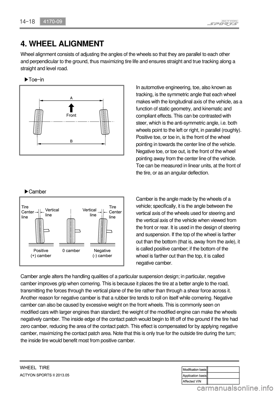
▶Toe-in
▶Camber
In automotive engineering, toe, also known as
tracking, is the symmetric angle that each wheel
makes with the longitudinal axis of the vehicle, as a
function of static geometry, and kinematic and
compliant effects. This can be contrasted with
steer, which is the anti-symmetric angle, i.e. both
wheels point to the left or right, in parallel (roughly).
Positive toe, or toe in, is the front of the wheel
pointing in towards the center line of the vehicle.
Negative toe, or toe out, is the front of the wheel
pointing away from the center line of the vehicle.
Toe can be measured in linear units, at the front of
the tire, or as an angular deflection.
Camber is the angle made by the wheels of a
vehicle; specifically, it is the angle between the
vertical axis of the wheels used for steering and
the vertical axis of the vehicle when viewed from
the front or rear. It is used in the design of steering
and suspension. If the top of the wheel is farther
out than the bottom (that is, away from the axle), it
is called positive camber; if the bottom of the
wheel is farther out than the top, it is called
negative camber. Wheel alignment consists of adjusting the angles of the wheels so that they are parallel to each other
and perpendicular to the ground, thus maximizing tire life and ensures straight and true tracking along a
straight and level road.
Camber angle alters the handling qualities of a particular suspension design; in particular, negative
camber improves grip when cornering. This is because it places the tire at a better angle to the road,
transmitting the forces through the vertical plane of the tire rather than through a shear force across it.
Another reason for negative camber is that a rubber tire tends to roll on itself while cornering. Negative
camber can also be caused by excessive weight on the front wheels. This is commonly seen on
modified cars with larger engines than standard; the weight of the modified engine can make the wheels
negatively camber. The inside edge of the contact patch would begin to lift off of the ground if the tire had
zero camber, reducing the area of the contact patch. This effect is compensated for by applying negative
camber, maximizing the contact patch area. Note that this is only true for the outside tire during the turn;
the inside tire would benefit most from positive camber.