2013 SSANGYONG NEW ACTYON SPORTS brake sensor
[x] Cancel search: brake sensorPage 38 of 751

02-70000-00
3. CHECK AND INSPECTION
1) Cylinder
(1) Compression pressure test
Specified value ▶
Compression ratio16.5 : 1
Test conditionat normal operating temperature (80˚C)
Compression pressureStandard32 bar
Minimum18 bar
Differential limit between cylindersMaximum 3 bar
The compression pressure test is to check the conditions of internal components (piston, piston ring,
intake and exhaust vale, cylinder head gasket). This test provides current engine operating status.
Before cranking the engine, make sure that the test wiring, tools and persons are keeping away
from moving components of engine (e.g., belt and cooling fan).
Park the vehicle on the level ground and apply the parking brake.
Do not allow anybody to be in front of the vehicle. -
-
-
Measurement ▶
<007e0088009900940047009b008f008c0047008c0095008e00900095008c0047009c00970047009b00960047009500960099009400880093004700960097008c00990088009b00900095008e0047009b008c00940097008c00990088009b009c0099008c00
47004f005f005700b6006a00500055>
Disconnect the fuel rail pressure sensor connector to cut off the fuel injection.
Remove the air cleaner duct and glow plugs. -
-
-
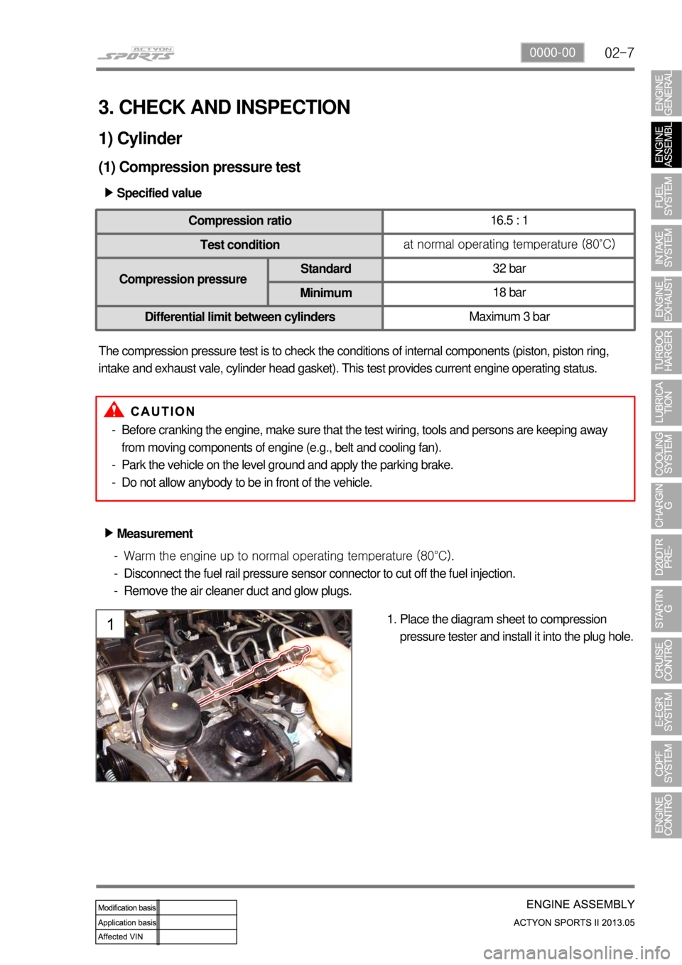
Place the diagram sheet to compression
pressure tester and install it into the plug hole. 1.
Page 203 of 751

15-30000-00
1. ENGINE DATA LIST
Data Unit Value
Coolant temperature℃ 0.436 V (130℃) to 4.896 V (-40℃)
Intake air temperature℃ -40 to 130℃ (varies by ambient air
temperature or engine mode)
Idle speed rpm750 ± 20
Engine load % 18~25%
Mass air flow kg/h 16 to 25 kg/h
Throttle position angle°TA 0° (Full Open) to 78° (Close)
Engine torque Nm varies by engine conditions
Injection time ms 3 to 5ms
Battery voltage V 13.5 V to 14.1 V
Accelerator pedal position 1 V 0.4. to 4.8V
Accelerator pedal position 2 V 0.2 to 2.4 V
Throttle position 1 V 0.3 to 4.6 V
Throttle position 2 V 0.3 to 4.6 V
Oxygen sensor mV 0 to 5 V
A/C compressor switch 1=ON / 0=OFF -
Full load 1=ON / 0=OFF -
Gear selection (A/T) 1=ON / 0=OFF -
Knocking control 1=ON / 0=OFF -
Brake switch 1=ON / 0=OFF -
Cruise control 1=ON / 0=OFF -
Page 209 of 751

15-90000-00
Fuel rail pressure
sensor
(2) Components for ECU Input
CAN
- ABS & ESP
- GCU
- Instrument
cluster
- TCUSwirl valve
position sensor
Differential
pressure sensorE-EGR valve
position sensorCamshaft position
sensorCoolant
temperature
sensor
Exhaust gas
temperature
sensorHFM sensorOxygen sensorT-MAP sensor
Crankshaft
position sensorAccelerator pedal
sensorThrottle position
sensorKnock sensor
-Auto cruise switch
- Rear right wheel
speed (without ABS)
- Refrigerant pressure
sensor
- Clutch pedal signal
- Blower switch signal
- Brake pedal signal
Water sensor
Page 211 of 751

15-110000-00
2) ECU Control
(1) Function
a. ECU Function
ECU receives and analyzes signals from various sensors and then modifies those signals into
permissible voltage levels and analyzes to control respective actuators.
ECU microprocessor calculates injection period and injection timing proper for engine piston speed and
crankshaft angle based on input data and stored specific map to control the engine power and emission
gas.
Output signal of the ECU microprocessor drives pressure control valve to control the rail pressure and
activates injector solenoid valve to control the fuel injection period and injection timing; so controls
various actuators in response to engine changes. Auxiliary function of ECU has adopted to reduce
emission gas, improve fuel economy and enhance safety, comforts and conveniences. For example,
there are EGR, booster pressure control, autocruise (export only) and immobilizer and adopted CAN
communication to exchange data among electrical systems (automatic T/M and brake system) in the
vehicle fluently. And Scanner can be used to diagnose vehicle status and defectives.
<00760097008c00990088009b00900095008e0047009b008c00940097008c00990088009b009c0099008c0047009900880095008e008c00470096008d0047006c006a007c00470090009a0047009500960099009400880093009300a000470054005b005700
47009b009600470052005f005c00b6006a004700880095008b> protected from factors like oil,
water and electromagnetism and there should be no mechanical shocks.
To control the fuel volume precisely under repeated injections, high current should be applied instantly
so there is injector drive circuit in the ECU to generate necessary current during injector drive stages.
Current control circuit divides current applying time (injection time) into full-in-current-phase and hold-
current-phase and then the injectors should work very correctly under every working condition.
b. Control Function
Controls by operating stages
To make optimum combustion under every operating stage, ECU should calculate proper injection
volume in each stage by considering various factors.
Starting injection volume control
During initial starting, injecting fuel volume will be calculated by function of temperature and engine
cranking speed. Starting injection continues from when the ignition switch is turned to ignition
position to till the engine reaches to allowable minimum speed.
Driving mode control
If the vehicle runs normally, fuel injection volume will be calculated by accelerator pedal travel and
engine rpm and the drive map will be used to match the drivers inputs with optimum engine power. -
-
-
Page 314 of 751

02-4
Input Signals
▶
NO.
Input Signal Name Logic Status
1 IGN1 ON = BAT
(IGN ON or START)
2 IGN2 ON = BAT (IGN ON)
3 ALT_D ON = BAT (engine started)
4 Key reminder switch IN = BAT (key in)
5 Driver's door switch OPEN = GND, CLOSE = OPEN
6 Passenger's door switch OPEN = GND, CLOSE = OPEN
7 Rear door switch - OPEN (one of rear doors) = GND
- CLOSE (all rear doors) = OPEN
8 Hood switch OPEN = GND, CLOSE = OPEN
9 Driver's door lock/unlock switch LOCK = OPEN, UNLOCK = GND
10 Passenger's door lock/unlock switch LOCK = OPEN, UNLOCK = GND
11 Rear door lock/unlock switch - UNLOCK (one of rear doors)
= GND
- LOCK (all rear doors) = OPEN
12 Tailgate lock/unlock switch LOCK = OPEN, UNLOCK = GND
13 Rear defogger switch ON = GND, OFF = OPEN
14 Seat belt switch Unfastened = GND, Fastened = OPEN
15 Sunroof open switch ON = GND, OFF = OPEN
16 Parking brake switch ON = GND, OFF = OPEN
17 Air bag collision sensor ON = 200 ms output (LOW), OFF = OPEN
18 Wiper motor (parking) switch STOP = BAT VOLTAGE, ROTATING = GND
19 Washer switch ON = BAT, OFF = OPEN
20 INT-AUTO switch ON = BAT, OFF = OPEN
21 Auto washer switch ON = BAT, OFF = OPEN
22 Intermittent resistance 0W ~ 51KW (for intermittent wiper)
23 Speed sensor ON = GND (PWM), OFF = OPEN
24 Mirror lock/unlock switch ON = GND, OFF = OPEN
25 Front defogger switch ON = GND, OFF = OPEN
26 Auto hazard switch ON = GND, OFF = OPEN
Page 404 of 751

04-218210-01
ABS Warning Light
This warning light comes on
when the ignition switch is turned
to "ON" position and should go
out if the system is normal.
The vehicle with ABS performs
self-diagnosis. During this
diagnosis, brake pedal vibration
and noise may be apparent
when the driving motors
discharges the hydraulic
pressure from the internal
hydraulic device.4WD IndicatorLow Fuel Level
Warnig Light
This warning light
comes on when the
fuel will soon be
exhausted. The time
it takes turn on,
however, varies
according to the
gradient of the
vehicle.
4WD HIGH Indicator
The lamp blinks momentarily during
the change of driving mode.
4WD LOW Indicator
The lamp blinks momentarily during
the change of driving mode.
4WD CHECK Warning Light
This indicates that there is something
wrong in the transfer case system.
(check the system) -
-
-
Auto Cruise Control
Indicator
Operating the cruise
control switch turns on
the indicator lamp to
indicate the cruise
control system is
activated.
Water Separator Warning Light
This lamp comes on to warn the driver of
water in the fuel tank which causes the loss
of engine power. When a certain amount of
water is accumulated, the lamp comes on
and a chime sounds.
Engine CHECK Warning Light
This warning light comes on when the
ignition switch is turned to "ON"
position and should go out if the
system related to engine control is
normal.
This comes on when different sensors
and devices related to engine control
are defective.
Winter Mode
Indicator
Pressing the "W" side of the
automatic transmission mode
selector switch switches the driving
mode to winter mode and turns on
the indicator lamp.
Use this mode to drive off smoothly
on icy and slippery roads.
Charge Warning Light
This warning light comes on when the
ignition switch is turned on and go off when
the engine is started.
If this light doesn't go off after engine starting,
it means there is a malfunction in the system.
Engine Hood Open Warning Light
When the engine hood is open, this light
comes on to inform the driver.
Hazard Indicator
This indicator blinks when the
hazard warning flashers are
switched on.
Page 449 of 751

01-33680-01
1. GENERAL INFORMATION
Six forward speeds
One reverse gear
A toruqe converter with an integral converter
lock-up clutch
Electronic shift and pressure controls
A single planetary gear-set
A double planetary gear-set
Two hydraulically controlled brake bands
Three multi-plate clutches
All hydraulic functions are directed by electronic
solenoids to control -
-
-
-
-
-
-
-
- Automatic transaxle (DSI M78) ▶
TCU ▶
TCU is located under the driver's seat and controls the operations of transmission.
TCU receives the ignition voltage and has three connectors (16-pin, 12-pin, 20-pin).
TCU receives input signals from certain transmission-related sensors, gear select lever and inhibitor
switch. TCU also uses these signals when determining transmission operating strategy. TCU uses
PCAN to communicate with other units. And, TCU communicates with engine ECU, ESP unit, TCCU
and instrument cluster through CAN lines to control the gear shifting and to recognize the current gear
position.
TCU
Page 457 of 751

01-113680-01
1. OVERVIEW
The six speed automatic (M78) transmission is
available in two variants: four wheel drive and
two wheel drive.
The transmission has the following features:
Six Forward Speeds
One reverse gear
A torque converter with an integral converter lock-up clutch
Electronic shift and pressure controls
A single planetary gear-set
A double planetary gear-set
Two hydraulically controlled brake bands
Three multi-plate clutches
All hydraulic functions are directed by electronic solenoids to control: -
-
-
-
-
-
-
-
-
Engagement feel
Shift feel
Shift scheduling
Modulated torque converter clutch applications ·
·
·
·
The transmission contains fully synthetic automatic transmission fluid (ATF) and is filled for life; therefore
it does not require periodic servicing.
Engine power reaches the transmission via a torque converter with integral converter lock-up clutch.
The six forward gears and one reverse gear are obtained from a single planetary set, followed by a
double planetary set. This type of gear-set arrangement is commonly known as Lepelletier type gear-set.
The automatic transmission is electronically controlled. The control system is comprised of the following
elements:
External transmission control unit (TCU)
Internal embedded memory module (EMM)
Input and output speed sensors
Valve body unit comprised of four on/off solenoid valves and six variable bleed solenoids
Torque converter -
-
-
-
-