Page 552 of 751

09-34850-01
1. SPECIFICATION
Unit Description Specification
Front brake Type Ventilated disc
Outer diameter of discØ294 mm
Inner diameter of caliper cylinderØ43.0 x 2 mm
Thickness of disc 28 mm (wear limit: 25.4 mm)
Area of brake pad Above 60 cm2
Pad wear indicator Mechanical type
Rear brake Type Solid disc
Outer diameter of discØ299 m
Thickness of disc 10.4 mm (wear limit: 8.5 mm)
Area of brake pad Above 28.8 cm2
Pad wear indicator Mechanical type
Brake booster Type Vacuum assist type
Size8” + 9” (Tandem)
Master cylinder Type Tandem type(integrated level sensor)
Inner diameter of cylinderØ26.99 mm
Brake pedal Maximum operating stroke 150 mm
Pedal ratio 4 : 1
Free play 3 to 10 mm
Parking brake Type Mechanically expanded rear lining
Operating type Hand operated type
Inner diameter of drumØ190 mm
Brake oil Specification DOT 4
Capacity As required
Service Interval: Change the brake oil at every 2 years
DOT?
It is the quality grade of brake fluid established by US Department of Transportation.
Page 577 of 751
09-28
Front Brake AssemblyFront Wheel Speed Sensor (4WD)
HECU
2. SYSTEM LAYOUT
Master Cylinder and Booster
Brake Pedal
Page 578 of 751
09-294850-01
Rear Wheel Speed Sensor (4WD)
Rear Brake Assembly
ABS/EBD Indicators
Parking Brake Lever
Parking Brake
Page 589 of 751
10-94892-01
Front wheel speed sensor
(4WD)
Located on the hub assembly.
Front discFront caliper assembly
(2WD/4WD)
Located on the knuckle.
ABS hydraulic device and control unit
Located near the brake booster in engine compartment.
Page 590 of 751
10-10
3. ABS CONTROL LOGIC
The principal ABS control logic is the determination of the reference speed by choosing one wheel
meeting a certain condition, while sensing the speed information from 4 wheel speed sensors when the
vehicle is being driven.
For example, when the comparison of the reference speed with front right wheel speed shows a slip, the
control signal is determined according to whether it's deceleration or acceleration. If the control
conditions are met, the brake for the front right wheel will be got under control.
Page 592 of 751

10-12
2) EBD (Electronic Brake-force Distribution) Warning Lamp
EBD warning lamps (brake warning lamp and ABS warning lamp) come on when the system performs
the self diagnosis and when it detects the malfunction of EBD system. However, the brake warning lamp
comes on regardless of EBD system when the parking brake is applied.
EBD warning lamp ON:
When turning the ignition switch to ON position, ABS warning lamp and the brake warning lamp
comes on for 3 seconds for self diagnosis and goes off if the system is OK (initialization mode).
When applying the parking brake, the brake warning lamp comes on.
When the brake fluid is not sufficient, the brake warning lamp comes on.
When disengaging the connector, the warning lamp comes on.
When the system is defective, ABS warning lamp and the brake warning lamp come on
simultaneously. A.
B.
C.
D.
E.
When the solenoid valve is defective
When one or more wheel sensors are defective
When ABS HECU is defective
When the voltage is abnormal
When valve relay is defective a.
b.
c.
d.
e.
When the communication between warning lamp CAN modules in meter cluster is failed, the
warning lamp comes on. F.
Page 597 of 751
10-174892-01
3) Basic ABS Control
Operation of ABS control unit ▶
Applications of the ABS control unit The signals
produced by the wheel sensors are evaluated
in the electronic control unit. From the
information received, the control unit must first
compute the following variables:
Wheel speed
Reference speed
Deceleration
Slip -
-
-
-
Reference speed ▶
The reference speed is the mean, I.e. average speed of all wheel speeds determined by simple
approximation.
Simplified ABS control ▶
If, during braking, one wheel speed deviates from the reference speed, the ABS control unit attempts to
correct that wheel speed by modulating the brake pressure until it again matches the reference speed.
When all four wheels tend to lock, all four wheels speeds suddenly deviate from the previously
determined reference speed. In that case, the control cycle is initiated again in order to again correct the
wheel speed by modulating the brake pressure.
Page 599 of 751

10-194892-01
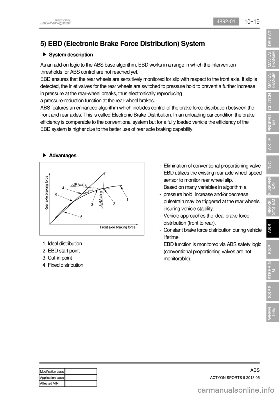
5) EBD (Electronic Brake Force Distribution) System
System description ▶
As an add-on logic to the ABS base algorithm, EBD works in a range in which the intervention
thresholds for ABS control are not reached yet.
EBD ensures that the rear wheels are sensitively monitored for slip with respect to the front axle. If slip is
detected, the inlet valves for the rear wheels are switched to pressure hold to prevent a further increase
in pressure at the rear-wheel breaks, thus electronically reproducing
a pressure-reduction function at the rear-wheel brakes.
ABS features an enhanced algorithm which includes control of the brake force distribution between the
front and rear axles. This is called Electronic Brake Distribution. In an unloading car condition the brake
efficiency is comparable to the conventional system but for a fully loaded vehicle the efficiency of the
EBD system is higher due to the better use of rear axle braking capability.
Advantages ▶
Elimination of conventional proportioning valve
EBD utilizes the existing rear axle wheel speed
sensor to monitor rear wheel slip.
Based on many variables in algorithm a
pressure hold, increase and/or decrease
pulsetrain may be triggered at the rear wheels
insuring vehicle stability.
Vehicle approaches the ideal brake force
distribution (front to rear).
Constant brake force distribution during vehicle
lifetime.
EBD function is monitored via ABS safety logic
(conventional proportioning valves are not
monitorable). -
-
-
-
-
Ideal distribution
EBD start point
Cut-in point
Fixed distribution 1.
2.
3.
4.