Page 99 of 751
03-22
2. SYSTEM LAYOUT AND OPERATION
1) Layout
For sensor and actuator control logic, refer to Chapter "Engine Control".
Engine ECU (D20DTR)
Engine control by various
signalsFuel tank
Fuel metering by sender
HFM sensor
Measuring intake air mass and
temperature
Crankshaft position sensor
Measuring engine rpmInjector (C3I)
Pre-injection, main injection,
after-injection by signals from
ECUCamshaft position sensor
Determining injection order
Page 100 of 751
03-232210-01
Accelerator pedal position
sensor
Detecting driver's intention
for speed up/down
Fuel rail assembly
Relieving the pulsation.
Measuring the fuel pressure.
Distributing the fuel to injectors.
Fuel filter assembly
Supplying clean fuel/fuel
heating/water separation by
priming pump
Plunger type HP pump (1,800 bar)
Vane type LP pump (6 bar)
T-MAP sensor
Measuring booster pressure
and temperature
High pressure pump
Generating high pressurized fuel and
supplying it according to engine rpm,
required volume, required pressure
Page 101 of 751

03-24
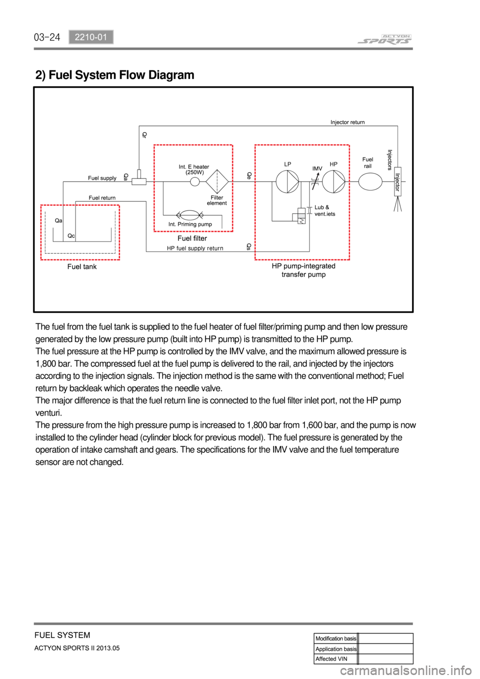
2) Fuel System Flow Diagram
The fuel from the fuel tank is supplied to the fuel heater of fuel filter/priming pump and then low pressure
generated by the low pressure pump (built into HP pump) is transmitted to the HP pump.
The fuel pressure at the HP pump is controlled by the IMV valve, and the maximum allowed pressure is
1,800 bar. The compressed fuel at the fuel pump is delivered to the rail, and injected by the injectors
according to the injection signals. The injection method is the same with the conventional method; Fuel
return by backleak which operates the needle valve.
The major difference is that the fuel return line is connected to the fuel filter inlet port, not the HP pump
venturi.
The pressure from the high pressure pump is increased to 1,800 bar from 1,600 bar, and the pump is now
installed to the cylinder head (cylinder block for previous model). The fuel pressure is generated by the
operation of intake camshaft and gears. The specifications for the IMV valve and the fuel temperature
sensor are not changed.
Page 103 of 751

03-26
The engine ECU calculates the accelerator pedal based on the input signals from various sensors, and
controls the overall operation of the vehicle.
The ECU receives the signals from various sensor through data line, and performs effective air-fuel ratio
control based on these signals.
The crankshaft speed (position) sensor measures the engine speed, and the camshaft speed (position)
sensor determines the order of injections, and the ECU detects the amount of the accelerator pedal
depressed (driver's will) by receiving the electrical signals from the accelerator pedal sensor.
The mass air flow sensor detects the volume of intake air and sends the value to the ECU.
The major function of the ECU is controlling air-fuel ratio to reduce the emission level (EGR valve control)
by detecting instantaneous air flow change with the signals from the mass air flow sensor.
Also, the ECU uses the signals from the coolant temperature & air temperature sensors, booster pressure
sensor, atmospheric pressure sensor to: a) determine injection starting point and set value for pilot
injection, and b) deal with various operations and variable conditions.
Page 193 of 751
14-92412-02
Differential pressure
sensor
Calculates the amount of
PM collected by reading the
pressure difference between
before and after the CDPF.Engine ECU
DCM 3.7
Post-injectionThrottle
valve
Regulates the rate of air
intake.
CDPF
DOC+DPFFront temperature
sensor
Protects the turbocharger.Rear temperature sensor
Measures the temperature
of fuel combustion.
2. COMPONENT
For details, refer to section "Engine Control". *
Page 194 of 751

14-10
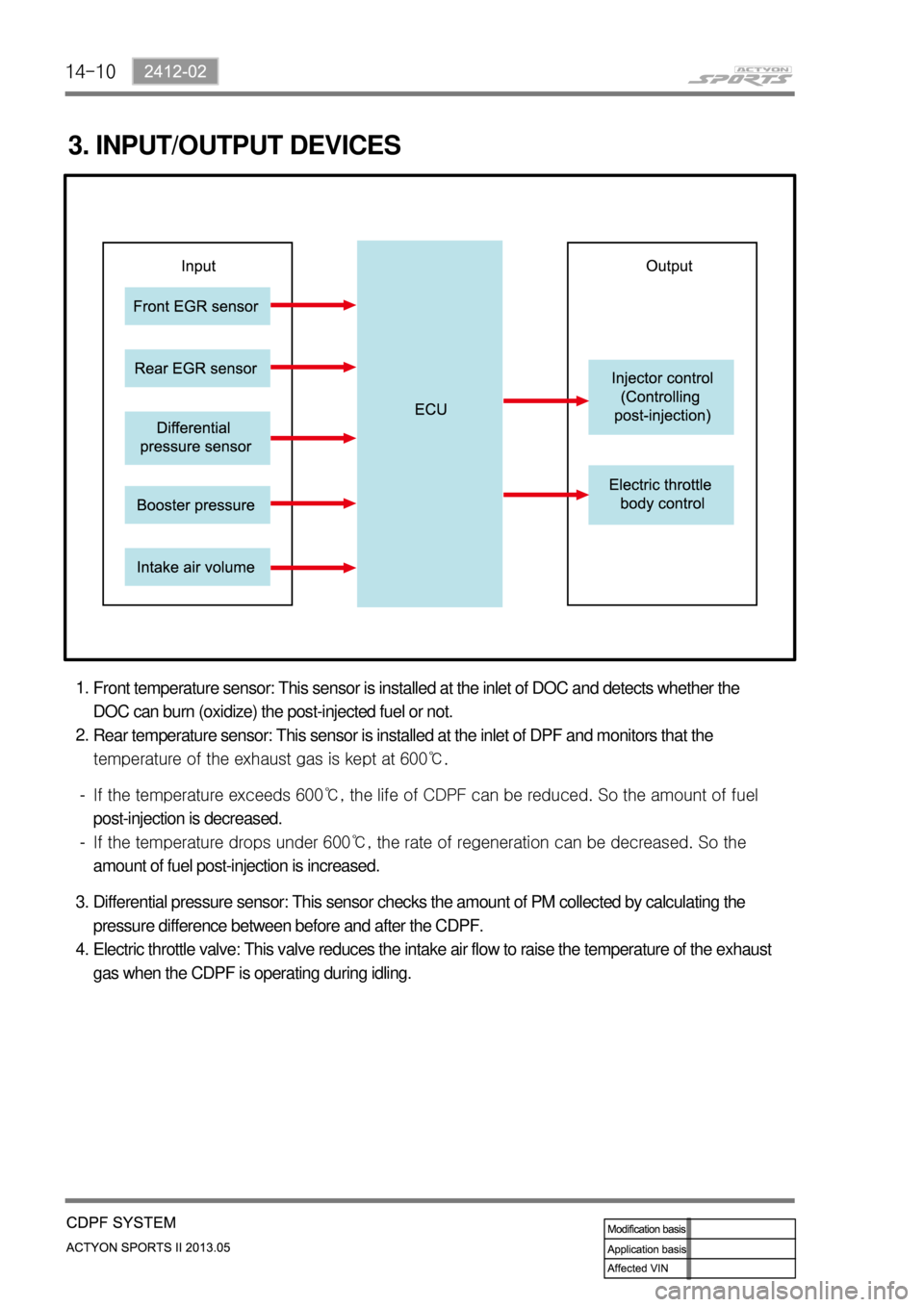
3. INPUT/OUTPUT DEVICES
Front temperature sensor: This sensor is installed at the inlet of DOC and detects whether the
DOC can burn (oxidize) the post-injected fuel or not.
Rear temperature sensor: This sensor is installed at the inlet of DPF and monitors that the
temperature of the exhaust gas is kept at 600℃. 1.
2.
<0070008d0047009b008f008c0047009b008c00940097008c00990088009b009c0099008c0047008c009f008a008c008c008b009a0047005d005700570b4500530047009b008f008c004700930090008d008c00470096008d0047006a006b0077006d004700
8a0088009500470089008c00470099008c008b009c008a008c>d. So the amount of fuel
post-injection is decreased.
<0070008d0047009b008f008c0047009b008c00940097008c00990088009b009c0099008c0047008b009900960097009a0047009c0095008b008c00990047005d005700570b4500530047009b008f008c004700990088009b008c00470096008d0047009900
8c008e008c0095008c00990088009b0090009600950047008a>an be decreased. So the
amount of fuel post-injection is increased. -
-
Differential pressure sensor: This sensor checks the amount of PM collected by calculating the
pressure difference between before and after the CDPF.
Electric throttle valve: This valve reduces the intake air flow to raise the temperature of the exhaust
gas when the CDPF is operating during idling. 3.
4.
Page 195 of 751

14-112412-02
4. POST-INJECTION AND AIR MASS CONTROL
A DPS (Differential Pressure Sensor) measures the pressure difference between before and after the
CDPF and detects whether the soot is collected in the CDPF or not. If PM is collected in the CDPF (In
this case the pressure difference between before and after the CDPF exceeds the specified value.
Normally, the system sends the signal when the driving distance becomes approx. 600 to 1,200 km), the
temperature of exhaust gas is increased and the post-injection is started for regeneration. The amount of
fuel post-injection is controlled by the exhaust gas temperature measured by the rear temperature
<009a008c0095009a00960099005500470070008d0047009b008f008c0047009b008c00940097008c00990088009b009c0099008c00470090009a00470093008c009a009a0047009b008f008800950047005d005700570b4500530047009b008f008c004700
8800940096009c0095009b00470096008d004700970096009a>t-injection is increased to
increase the regeneration temperature. Otherwise, the fuel injection amount is decreased or the fuel is
not injected.
When the engine is running with low load, the intake air amount is also controlled as well as fuel injection
amount. This function is used to increaser the combustion temperature by increasing the amount of fuel
post-injection with the lowest air amount within the specified control logic.
Page 196 of 751

14-12
Front temperature sensor
Measures the temperature of
exhaust gas.
This sensor is located at the rear
side of exhaust manifold and
monitors the temperature of
combusted gas to prevent the
exhaust system from overheating.
When the temperature gets higher,
this sensor cuts off the fuel delivery
and controls the EGR to lower the
temperature.Rear temperature sensor
Measure the outlet
temperature of DOC.
This sensor is located at the
rear side of DOC and
monitors the overheating of
CDPF and post injection
volume.
Engine ECU (D20DTR)
Differential pressure sensor
Measures the difference between
inlet and outlet pressures of CDPF.
If the difference is higher than the
specified value when collecting the
PM, this makes the post injection for
forced recycling of PM.
T-MAP sensorIntake air
mass
Measures
the
excessive
amount of
PM.
Boos
t
pressure
/
temperature
Injector (C31)
Controls the post injection.
Electric throttle body
Controls the intake air mass.
HFM sensor
Wide band
oxygen senso
r