2013 SSANGYONG NEW ACTYON SPORTS automatic transmission
[x] Cancel search: automatic transmissionPage 191 of 751

14-72412-02
1. OVERVIEW
The low emission vehicle is being sold increasingly in the market as a countermeasure for complying
with the environment regulations such as a special act on Seoul metropolitan air quality improvement
and for reducing the PM (Particulate Material) from the diesel-powered vehicle. For the CDPF system,
the DOC (two-way catalytic converter or catalytic combustion system) fitted to the conventional diesel
engine has the high purification rate for HC or CO but not have a high reduction rate for the PM. For this
reason, a necessity has been raised in order to consider a countermeasure to reduce the PM since the
existing DOC can't meet the regulation, which is getting tighter.
This results in a development of the CDPF (Catalyst & Diesel Particulate Filter) that is combination of the
existing DOC (Diesel Oxydation Catalyst) and DPF (Diesel Particulate Filter). While the DOC converts
the CO and HC into the CO2 and H2O - unharmful to human body - using a oxidation reaction, the DPF
collects the PF (Particulate Material) for regeneration of it. However, each of these devices can only
reduce a part of the exhaust gas. This evoked the necessity of the CDPF with both features. The DOC
capacity is more on the manual transmission than the automatic transmission.
DPF(Diesel Particulate Filter) ▶DOC(Diesel Oxidation Catalyst) ▶
It is called as a oxidation catalyst, which purifies CO and HC in exhaust gas. The three-way catalyst is
used for the gasoline vehicle. But, the diesel engine oxidates CO and HC excepting NOx into H2O and
CO2 in order to purify the exhaust gas since the exhaust gas has a rich oxygen at all times.
It consists of mainly the aluminum and titanium and there is a porous thin film, which emits the exhaust
gas but does not emit the PM in it. It emits the exhaust gas generated during combustion and filters the
PM which is a byproduct of combustion to burn it when a certain amount of it is collected in the filter.
When a certain amount of the PM builds up, exposure to high exhaust gas causes carbon, the
fundamental ingredient in PM, to burn and release into the atmosphere in form of CO2.
Page 239 of 751

15-390000-00
HFM (intake air
temperature)Cooling fan
module
DSI 6 A/T (ATF
temperature)Coolant
temperature
sensor
Refrigerant
pressure sensor
Relay box
(12) Cooling fan control
A. Overview of cooling fan and A/C compressor
The cooling system maintains the engine temperature at an efficient level during all engine operating
conditions. The water pump draws the coolant from the radiator. The coolant then circulates through
water jackets in the engine block, the intake manifold, and the cylinder head. When the coolant reaches
the operating temperature of the thermostat, the thermostat opens. The coolant then goes back to the
radiator where it cools. The heat from automatic transmission is also cooled down through the radiator
by circulating the oil through the oil pump. ECU controls the electric cooling fans with three cooling fan
relays to improve the engine torque and air conditioning performance.
For detailed information, refer to Chapter "Air Conditioning System".
B. Components
A/C compressor
D20DTR ECU
Page 258 of 751

01-91113-01
4. DIAGNOSTIC INFORMATION AND PROCEDURE
1) Oil Leak Diagnosis
Most fluid oil leaks are easily located and repaired by visually finding the leak and replacing or repairing
the necessary parts. On some occasions a fluid leak may be difficult to locate or repair. The following
procedures may help you in locating and repairing most leaks.
Finding the Leak ▶
Identify the fluid. Determine whether it is engine oil, automatic transmission fluid, power steering
fluid, etc.
Identify where the fluid is leaking from. -
-
After running the vehicle at normal operating temperature, park the vehicle over a large sheet
of paper.
Wait a few minutes.
You should be able to find the approximate location of the leak by the drippings on the paper. ·
·
·
Visually check around the suspected component.
Check around all the gasket mating surfaces for leaks. A mirror is useful for finding leaks in
areas that are hard to reach.
If the leak still cannot be found, it may be necessary to clean the suspected area with a
degreaser, steam or spray solvent. -
-
Clean the area well.
Dry the area.
Operate the vehicle for several miles at normal operating temperature and varying speeds.
After operating the vehicle, visually check the suspected component.
If you still cannot locate the leak, try using the powder or black light and dye method. ·
·
·
·
·
Clean the suspected area.
Apply an aerosol-type powder (such as foot powder) to the suspected area.
Operate the vehicle under normal operating conditoins.
Visually inspect the suspected component. You should be able to trace the leak path over the
white powder surface to the source. -
-
-
- Powder Method ▶
Page 297 of 751

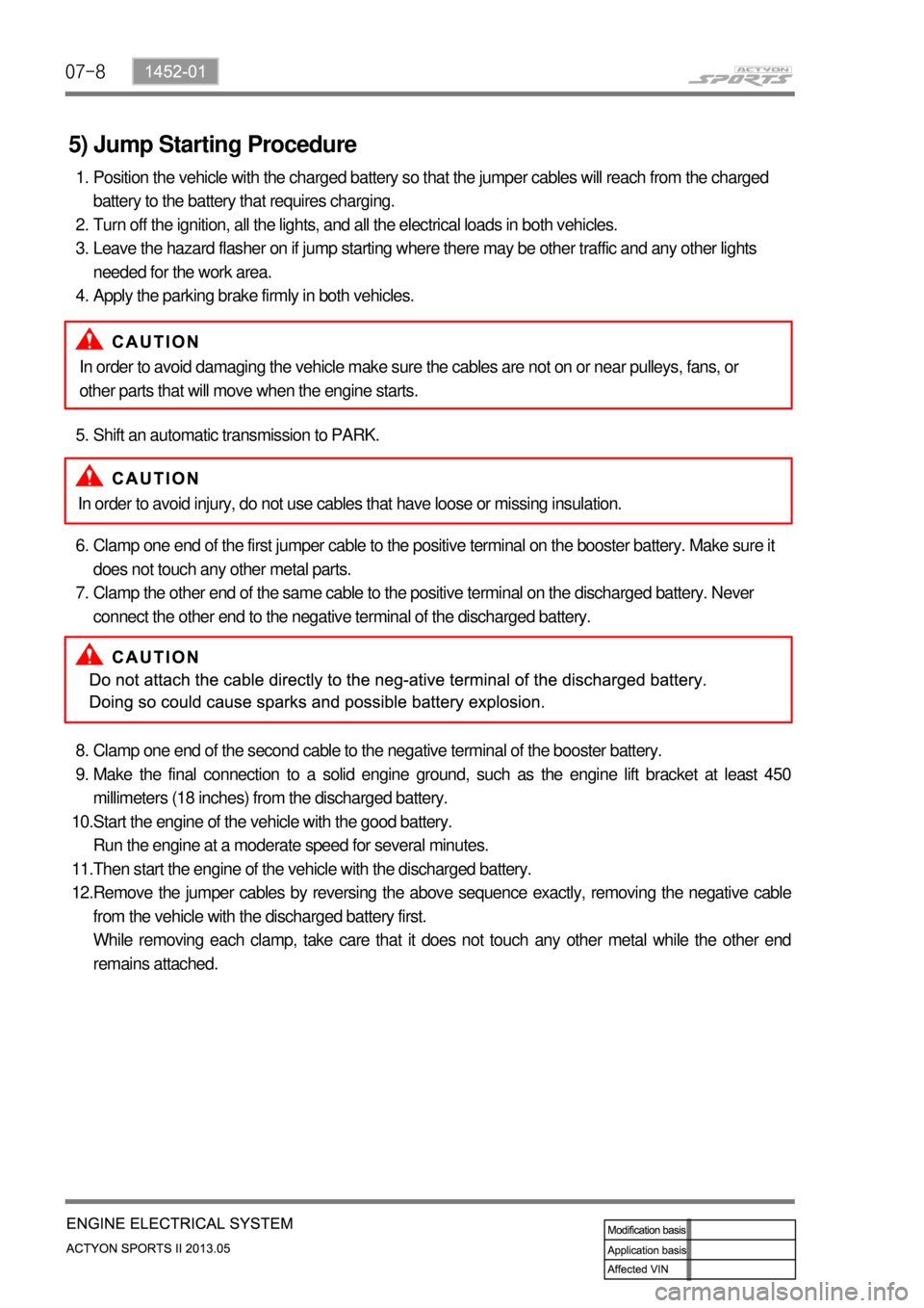
07-8
5) Jump Starting Procedure
Position the vehicle with the charged battery so that the jumper cables will reach from the charged
battery to the battery that requires charging.
Turn off the ignition, all the lights, and all the electrical loads in both vehicles.
Leave the hazard flasher on if jump starting where there may be other traffic and any other lights
needed for the work area.
Apply the parking brake firmly in both vehicles. 1.
2.
3.
4.
Shift an automatic transmission to PARK. 5.
Clamp one end of the first jumper cable to the positive terminal on the booster battery. Make sure it
does not touch any other metal parts.
Clamp the other end of the same cable to the positive terminal on the discharged battery. Never
connect the other end to the negative terminal of the discharged battery. 6.
7.
Clamp one end of the second cable to the negative terminal of the booster battery.
Make the final connection to a solid engine ground, such as the engine lift bracket at least 450
millimeters (18 inches) from the discharged battery.
Start the engine of the vehicle with the good battery.
Run the engine at a moderate speed for several minutes.
Then start the engine of the vehicle with the discharged battery.
Remove the jumper cables by reversing the above sequence exactly, removing the negative cable
from the vehicle with the discharged battery first.
While removing each clamp, take care that it does not touch any other metal while the other end
remains attached. 8.
9.
10.
11.
12.In order to avoid damaging the vehicle make sure the cables are not on or near pulleys, fans, or
other parts that will move when the engine starts.
In order to avoid injury, do not use cables that have loose or missing insulation.
Page 404 of 751

04-218210-01
ABS Warning Light
This warning light comes on
when the ignition switch is turned
to "ON" position and should go
out if the system is normal.
The vehicle with ABS performs
self-diagnosis. During this
diagnosis, brake pedal vibration
and noise may be apparent
when the driving motors
discharges the hydraulic
pressure from the internal
hydraulic device.4WD IndicatorLow Fuel Level
Warnig Light
This warning light
comes on when the
fuel will soon be
exhausted. The time
it takes turn on,
however, varies
according to the
gradient of the
vehicle.
4WD HIGH Indicator
The lamp blinks momentarily during
the change of driving mode.
4WD LOW Indicator
The lamp blinks momentarily during
the change of driving mode.
4WD CHECK Warning Light
This indicates that there is something
wrong in the transfer case system.
(check the system) -
-
-
Auto Cruise Control
Indicator
Operating the cruise
control switch turns on
the indicator lamp to
indicate the cruise
control system is
activated.
Water Separator Warning Light
This lamp comes on to warn the driver of
water in the fuel tank which causes the loss
of engine power. When a certain amount of
water is accumulated, the lamp comes on
and a chime sounds.
Engine CHECK Warning Light
This warning light comes on when the
ignition switch is turned to "ON"
position and should go out if the
system related to engine control is
normal.
This comes on when different sensors
and devices related to engine control
are defective.
Winter Mode
Indicator
Pressing the "W" side of the
automatic transmission mode
selector switch switches the driving
mode to winter mode and turns on
the indicator lamp.
Use this mode to drive off smoothly
on icy and slippery roads.
Charge Warning Light
This warning light comes on when the
ignition switch is turned on and go off when
the engine is started.
If this light doesn't go off after engine starting,
it means there is a malfunction in the system.
Engine Hood Open Warning Light
When the engine hood is open, this light
comes on to inform the driver.
Hazard Indicator
This indicator blinks when the
hazard warning flashers are
switched on.
Page 449 of 751

01-33680-01
1. GENERAL INFORMATION
Six forward speeds
One reverse gear
A toruqe converter with an integral converter
lock-up clutch
Electronic shift and pressure controls
A single planetary gear-set
A double planetary gear-set
Two hydraulically controlled brake bands
Three multi-plate clutches
All hydraulic functions are directed by electronic
solenoids to control -
-
-
-
-
-
-
-
- Automatic transaxle (DSI M78) ▶
TCU ▶
TCU is located under the driver's seat and controls the operations of transmission.
TCU receives the ignition voltage and has three connectors (16-pin, 12-pin, 20-pin).
TCU receives input signals from certain transmission-related sensors, gear select lever and inhibitor
switch. TCU also uses these signals when determining transmission operating strategy. TCU uses
PCAN to communicate with other units. And, TCU communicates with engine ECU, ESP unit, TCCU
and instrument cluster through CAN lines to control the gear shifting and to recognize the current gear
position.
TCU
Page 452 of 751

01-6
4WD Automatic Transmission ▶
Torque converter
Oil cooler outletOil cooler return
Inhibiter switch Adapter housing
2) Appearance
Connector plug
Transfer case
Page 453 of 751

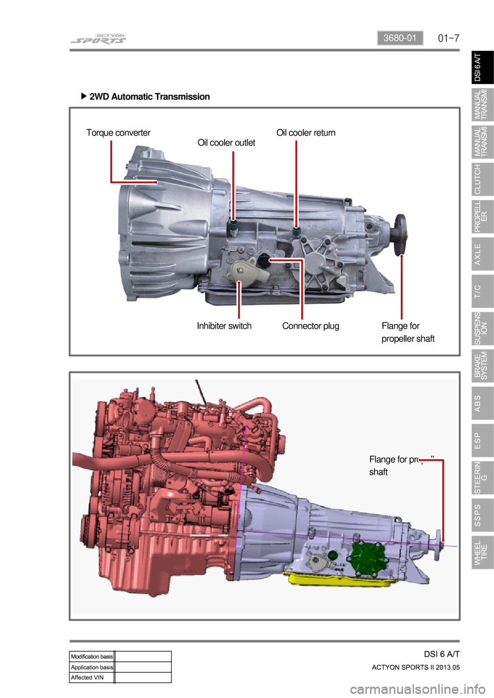
01-73680-01
2WD Automatic Transmission ▶
Torque converter
Oil cooler outletOil cooler return
Inhibiter switch Flange for
propeller shaft
Connector plug
Flange for propeller
shaft