2013 MITSUBISHI iMiEV service
[x] Cancel search: servicePage 99 of 258
WARNING
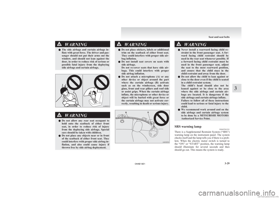
l The side airbags and curtain airbags in-
flate with great force. The driver and pas-
senger should not put their arms out the
window, and should not lean against the
door, in order to reduce risk of serious or
possible fatal injury from the deploying
side airbags and curtain airbags. WARNING
l Do
not allow any rear seat occupant to
hold onto the seatback of either front
seat, in order to reduce risk of injury
from the deploying side airbags. Special
care should be taken with children.
l Do not place any objects near or in front
of the seatback of either front seat. They
could interfere with proper side airbag in-
flation, and also could cause injury if
thrown free by side airbag deployment. WARNING
l Do
not place stickers, labels or additional
trim on the seatback of either front seat.
They could interfere with proper side air-
bag inflation.
l Do not install seat covers on seats with
side airbags.
Do not re-cover seats that have side air-
bags. This could interfere with proper
side airbag inflation.
l Do not attach a microphone (A) or any
other device or object around the part
where the curtain airbags (B) activate
such as on the windscreen, side door
glass, front and rear pillars and roof side
or assist grips. When the curtain airbags
inflate, the microphone or other device or
object will be hurled with great force or
the curtain airbags may not activate cor-
rectly, resulting in death or serious injury. WARNING
l Never install a rearward facing child re-
straint in the front passenger seat. A for-
ward facing child restraint should be
used in the rear seat whenever possible. If
a forward facing child restraint must be
used in the front passenger seat, adjust
the seat to the most rearward position,
and ensure that the child stays in the
child restraint and away from the door.
l Do not allow the child to lean against or
close to the door even if the child is seated
in a child restraint system.
The child’s head should also not be
leaned against or be close to the area
where the side airbags and curtain air-
bags are located. It is dangerous if the
side airbags and curtain airbags inflate.
Failure to follow all of these instructions
could lead to serious or fatal injury to the
child.
l We recommend work around and on the
side airbags and curtain airbags system
to be done by a MITSUBISHI MOTORS
Authorized Service Point.
SRS warning lamp E00407801591
There is a Supplemental Restraint System (“SRS”)
warning
lamp on the instrument panel. The system
checks itself and the lamp tells you if there is a prob-
lem. When the electric motor switch is turned to
the “ON” or “START” position, the warning lamp
should illuminate for several seconds and then
should go out. This means the system is ready. Seat and seat belts
3-29 3
OHAE13E1
Page 100 of 258
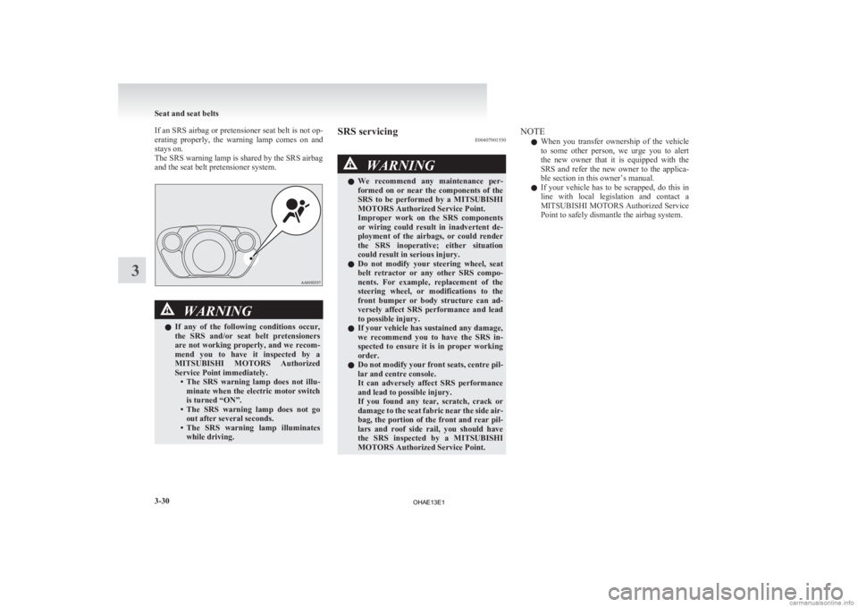
If an SRS airbag or pretensioner seat belt is not op-
erating
properly, the warning lamp comes on and
stays on.
The SRS warning lamp is shared by the SRS airbag
and the seat belt pretensioner system. WARNING
l If
any of the following conditions occur,
the SRS and/or seat belt pretensioners
are not working properly, and we recom-
mend you to have it inspected by a
MITSUBISHI MOTORS Authorized
Service Point immediately. • The SRS warning lamp does not illu-minate when the electric motor switch
is turned “ON”.
• The SRS warning lamp does not go out after several seconds.
• The SRS warning lamp illuminates while driving. SRS servicing
E00407901550 WARNING
l We
recommend any maintenance per-
formed on or near the components of the
SRS to be performed by a MITSUBISHI
MOTORS Authorized Service Point.
Improper work on the SRS components
or wiring could result in inadvertent de-
ployment of the airbags, or could render
the SRS inoperative; either situation
could result in serious injury.
l Do not modify your steering wheel, seat
belt retractor or any other SRS compo-
nents. For example, replacement of the
steering wheel, or modifications to the
front bumper or body structure can ad-
versely affect SRS performance and lead
to possible injury.
l If your vehicle has sustained any damage,
we recommend you to have the SRS in-
spected to ensure it is in proper working
order.
l Do not modify your front seats, centre pil-
lar and centre console.
It can adversely affect SRS performance
and lead to possible injury.
If you found any tear, scratch, crack or
damage to the seat fabric near the side air-
bag, the portion of the front and rear pil-
lars and roof side rail, you should have
the SRS inspected by a MITSUBISHI
MOTORS Authorized Service Point. NOTE
l When
you transfer ownership of the vehicle
to some other person, we urge you to alert
the new owner that it is equipped with the
SRS and refer the new owner to the applica-
ble section in this owner’s manual.
l If your vehicle has to be scrapped, do this in
line with local legislation and contact a
MITSUBISHI MOTORS Authorized Service
Point to safely dismantle the airbag system. Seat and seat belts
3-30
3
OHAE13E1
Page 102 of 258

Instruments
E005001012511- Energy level gauge
2-
Energy usage indicator
3- Odometer/Tripmeter/Meter illumination con- trol/Service reminder/Cruising range indica-
tor
4- Speedometer (km/h or MPH)
5- Reset button/Daytime dipper button/Selector button Speedometer
E00500201050
When
the electric motor switch is in the “ON” posi-
tion, the speedometer indicates the vehicle speed in
kilometers per hour (km/h) (Type 1) or miles per
hour (MPH) (Type 2).
Type 1 Type 2 NOTE
l The
display setting can be changed to the pre-
ferred units (km or miles) (Type 2).
Refer to “Changing the display unit*” on
page 4-02.
Changing the display unit* E00529500026
It is possible to select the speedometer’s display unit.
1. Press
the reset button (A) to display the od-
ometer (B).
(Refer to “To change the display” on page
4-03.) 2. Keep
the reset button pressed for two sec-
onds or longer to change the display unit
from MPH to km/h or from km/h to MPH. NOTE
l Once
the display unit has changed, keeping
the reset button pressed will not cause the dis-
play unit to change again.
The display unit for the cruising range will change
to match the selected speedometer display unit. Speedometer Cruising range
MPH Miles
km/h km NOTE
l Even
if speedometer display unit is changed,
the display units for the odometer, tripmeter,
and service reminder do not change. Instruments and controls
4-02
4
OHAE13E1
Page 103 of 258
Energy usage indicator
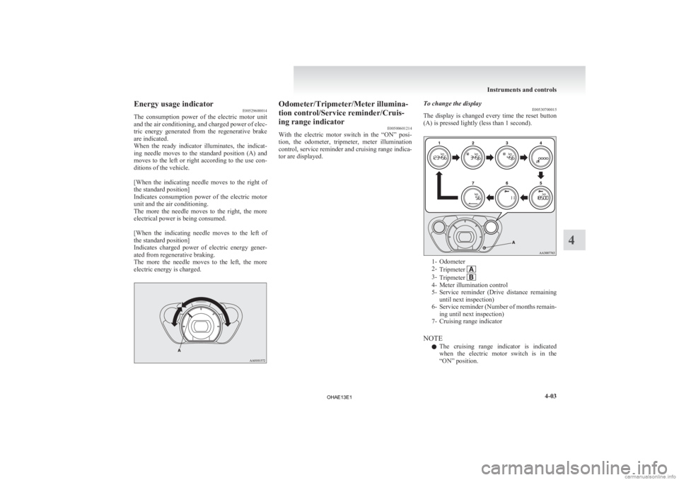
E00529600014
The
consumption power of the electric motor unit
and the air conditioning, and charged power of elec-
tric energy generated from the regenerative brake
are indicated.
When the ready indicator illuminates, the indicat-
ing needle moves to the standard position (A) and
moves to the left or right according to the use con-
ditions of the vehicle.
[When the indicating needle moves to the right of
the standard position]
Indicates consumption power of the electric motor
unit and the air conditioning.
The more the needle moves to the right, the more
electrical power is being consumed.
[When the indicating needle moves to the left of
the standard position]
Indicates charged power of electric energy gener-
ated from regenerative braking.
The more the needle moves to the left, the more
electric energy is charged. Odometer/Tripmeter/Meter illumina-
tion control/Service reminder/Cruis-
ing range indicator
E00500601214
With
the electric motor switch in the “ON” posi-
tion, the odometer, tripmeter, meter illumination
control, service reminder and cruising range indica-
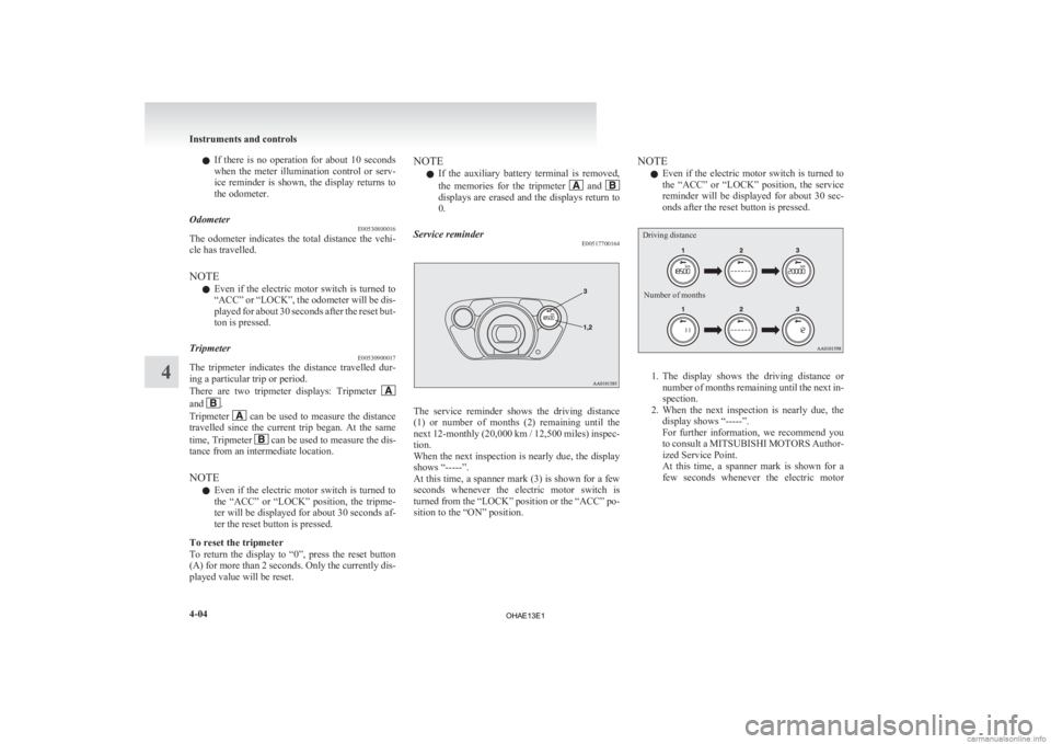
tor are displayed. To change the display
E00530700015
The
display is changed every time the reset button
(A) is pressed lightly (less than 1 second). 1- Odometer
2-
Tripmeter 3-
Tripmeter 4- Meter illumination control
5- Service
reminder (Drive distance remaining
until next inspection)
6- Service reminder (Number of months remain- ing until next inspection)
7- Cruising range indicator
NOTE l The cruising range indicator is indicated
when the electric motor switch is in the
“ON” position. Instruments and controls
4-03 4
OHAE13E1
Page 104 of 258
l
If there is no operation for about 10 seconds
when the meter illumination control or serv-
ice reminder is shown, the display returns to
the odometer.
Odometer E00530800016
The odometer indicates the total distance the vehi-
cle has travelled.
NOTE
l Even
if the electric motor switch is turned to
“ACC” or “LOCK”, the odometer will be dis-
played for about 30 seconds after the reset but-
ton is pressed.
Tripmeter E00530900017
The tripmeter indicates the distance travelled dur-
ing a particular trip or period.
There
are two tripmeter displays: Tripmeter and .
Tripmeter can be used to measure the distance
travelled
since the current trip began. At the same
time, Tripmeter can be used to measure the dis-
tance from an intermediate location.
NOTE
l Even
if the electric motor switch is turned to
the “ACC” or “LOCK” position, the tripme-
ter will be displayed for about 30 seconds af-
ter the reset button is pressed.
To reset the tripmeter
To return the display to “0”, press the reset button
(A) for more than 2 seconds. Only the currently dis-
played value will be reset. NOTE
l If
the auxiliary battery terminal is removed,
the memories for the tripmeter and
displays are erased and the displays return to
0.
Service reminder E00517700164 The service reminder shows the driving distance
(1)
or number of months (2) remaining until the
next 12-monthly (20,000 km / 12,500 miles) inspec-
tion.
When the next inspection is nearly due, the display
shows “-----”.
At this time, a spanner mark (3) is shown for a few
seconds whenever the electric motor switch is
turned from the “LOCK” position or the “ACC” po-
sition to the “ON” position. NOTE
l Even
if the electric motor switch is turned to
the “ACC” or “LOCK” position, the service
reminder will be displayed for about 30 sec-
onds after the reset button is pressed.
Driving distance
Number of months 1. The
display shows the driving distance or
number of months remaining until the next in-
spection.
2. When the next inspection is nearly due, the display shows “-----”.
For further information, we recommend you
to consult a MITSUBISHI MOTORS Author-
ized Service Point.
At this time, a spanner mark is shown for a
few seconds whenever the electric motor Instruments and controls
4-04
4
OHAE13E1
Page 105 of 258
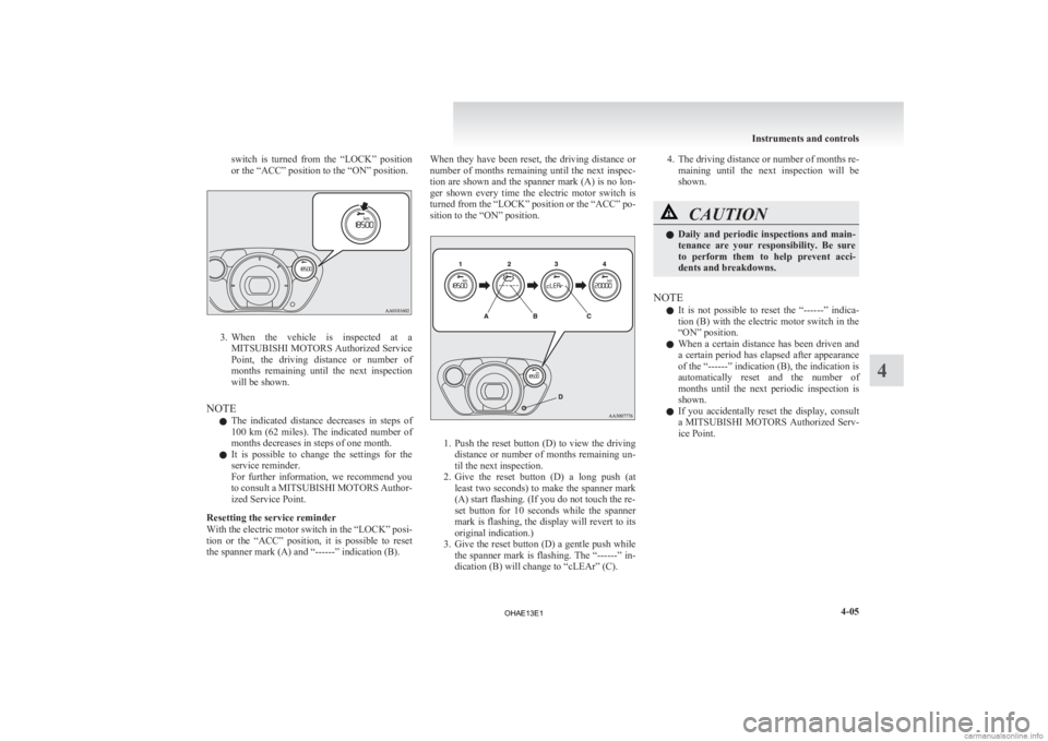
switch is turned from the “LOCK” position
or the “ACC” position to the “ON” position.
3. When the vehicle is inspected at a
MITSUBISHI MOTORS Authorized Service
Point, the driving distance or number of
months remaining until the next inspection
will be shown.
NOTE l The indicated distance decreases in steps of
100 km (62 miles). The indicated number of
months decreases in steps of one month.
l It is possible to change the settings for the
service reminder.
For further information, we recommend you
to consult a MITSUBISHI MOTORS Author-
ized Service Point.
Resetting the service reminder
With the electric motor switch in the “LOCK” posi-
tion or the “ACC” position, it is possible to reset
the spanner mark (A) and “------” indication (B). When they have been reset, the driving distance or
number
of months remaining until the next inspec-
tion are shown and the spanner mark (A) is no lon-
ger shown every time the electric motor switch is
turned from the “LOCK” position or the “ACC” po-
sition to the “ON” position. 1. Push
the reset button (D) to view the driving
distance or number of months remaining un-
til the next inspection.
2. Give the reset button (D) a long push (at least two seconds) to make the spanner mark
(A) start flashing. (If you do not touch the re-
set button for 10 seconds while the spanner
mark is flashing, the display will revert to its
original indication.)
3. Give the reset button (D) a gentle push while the spanner mark is flashing. The “------” in-
dication (B) will change to “cLEAr” (C). 4. The
driving distance or number of months re-
maining until the next inspection will be
shown. CAUTION
l
Daily
and periodic inspections and main-
tenance are your responsibility. Be sure
to perform them to help prevent acci-
dents and breakdowns.
NOTE l It
is not possible to reset the “------” indica-
tion (B) with the electric motor switch in the
“ON” position.
l When a certain distance has been driven and
a certain period has elapsed after appearance
of the “------” indication (B), the indication is
automatically reset and the number of
months until the next periodic inspection is
shown.
l If you accidentally reset the display, consult
a MITSUBISHI MOTORS Authorized Serv-
ice Point. Instruments and controls
4-05 4
OHAE13E1
Page 108 of 258

Indication and warning lamps
E00501502220Type 1Type 21-
Low energy warning indicator
® p. 4-07
2. Selector lever position indicator ® p. 5-10
3- High-beam indication lamp ® p. 4-09
4- Turn-signal indication lamps/Hazard warning indication lamps ® p. 4-09
5- Position lamp indication lamp ® p. 4-09
6- Front fog lamp indication lamp* ® p. 4-09
7- Service reminder ® p. 4-04
8- Driver’s and front passenger’s seat belt warning lamp ® p. 3-09
9- Supplement Restraint System (SRS) warning lamp ® p. 3-29
10- Rear fog lamp indication lamp ® p. 4-09
11- Ready indicator ® p. 4-09 12-
Auxiliary battery charge warning lamp ® p. 4-10
13- Electric power steering system (EPS) warning lamp ® p. 5-17
14- Electric motor unit warning lamp ® p. 4-10
15- Brake warning lamp ® p. 4-09
16- Anti-lock brake system (ABS) warning lamp ® p. 5-15
17- Power down warning lamp ® p. 4-11
18- Active stability control (ASC) indication lamp ® p. 5-19
19- Active stability control (ASC) OFF indication lamp ® p. 5-19
20- Charging indicator ® p. 4-09
21- Door ajar warning lamp ® p. 4-10
22- Rear passenger’s seat belt warning lamps* ® p. 3-10Instruments and controls
4-08 4
OHAE13E1
Page 109 of 258

Indication lamps
E00501600012Turn-signal indication lamps/
Hazard warning indication
lamps
E00501700374
These
indication lamps blink on and off
when a turn-signal lamp is operating.
NOTE
l If the blinking is too fast, the
cause may be a blown lamp bulb
or a faulty turn-signal connection.
When the hazard warning lamp switch is
pressed, all turn-signal lamps will flash
on and off continuously. High-beam indication lamp
E00501800072
This
indication lamp illuminates when
the high-beam is used. Front fog lamp indication
lamp*
E00501900132
This
indication lamp illuminates while
the front fog lamps are on. Rear fog lamp indication lamp
E00502000084
This
indication lamp illuminates while
the rear fog lamp is on. Position lamp indication lamp
E00508900102
This
lamp illuminates with the lamp
switch at “ ” or “ ” position
Ready indicator
E00530100019
This
indicator illuminates when the elec-
tric motor switch is turned to “START”
and driving becomes possible. Charging indicator
E00530200010
This
indicator flashes when the regular
charging cable or quick charging cable
is connected.
After that, the lamp switches to being il-
luminated when charging starts and goes
out when charging is completed. Warning lamps
E00502400017 Brake warning lamp
E00502502621
This
lamp comes on when the electric
motor switch is turned to the “ON” posi-
tion, and goes off after a few seconds
when the parking brake is released. Be-
fore driving your vehicle, release the
parking brake and make certain that the
brake warning lamp has gone off.
If the lamp stays on when the parking
brake is fully released, the service brake
system is not working properly or the
brake fluid level is low. WARNING
l If
any of the following condi-
tions occur, the brake effort
may significantly increase. Stop
the vehicle in a safe location,
avoiding where possible any
sudden brake application, and
contact a MITSUBISHI
MOTORS Authorized Service
Point. • The brake warning lampdoes not come on when the
electric motor switch is
turned to the “ON” position. Instruments and controls
4-09 4
OHAE13E1