Page 49 of 157

Note
The 12-Volt power socket will only work when ignition is switched on. ÐStorage compartments
Overview
The vehicle has the following storage compartments: Storage compartment on the driver's side » page 47
Storage compartment on the front passenger side » page 47
Stowage compartment with cover on the passenger side » page 48
Bag holder » page 48
Photo holder » page 48
Stowage compartment in front centre console » page 49
Multimedia holder » page 49
Meshed pockets at the front seat rests » page 49
Stowage compartments in front of the rear seats » page 49WARNING
■ Do not place anything on the dash panel. These objects might slide or fall
down when driving and may distract you from concentrating on the traffic –
risk of accident!
■ When driving, ensure that no objects from the centre console or from other
storage compartments can get into the driver's footwell. You would then no
longer be able to apply the brakes, operate the clutch or accelerator – risk of
accident! Ð Storage compartment on the driver's side
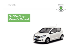
Fig. 49
Dash panel: Storage compart-
ment on the driver's side
The open stowage compartment can be found underneath the dash panel on the
driver's side » Fig. 49. WARNING
■ Ensure that when driving no objects from the centre console may get into
the driver's footwell. You would then no longer be able to apply the brakes,
operate the clutch or accelerator – risk of accident!
■ Never store hard, heavy or sharp items in an opened stowage compartment. Ð Storage compartment on the front passenger side
Fig. 50
Dash panel: Storage compart-
ment on the front passenger
side
The open stowage compartment can be found underneath the dash panel on the
driver's side » Fig. 50.
Bag hooks
There is a bag hook 1
» Fig. 50 at the open stowage compartment which is used
to hang smaller items of luggage, e.g. bags, or similar. £
47
Seats and Stowage
Page 50 of 157

CAUTION
The maximum permissible load of the hook is 1.5 kg. ÐStowage compartment with cover on the passenger side
Fig. 51
Dash panel: Storage compartment on the front passenger side
Open/close › To open, pull the opening lever 1
» Fig. 51.
Please read the following information if there is a foldable hook in the opening
lever » page 48
, in section Bag holder
.
› To close, push the cover upwards. The cover must engage firmly.
Overview of the stowage compartment:
Opening lever
Glasses storage box
Notepad holder
Pen holder
Coin holder
Card holder WARNING
The storage compartment must always be closed when driving for safety rea-
sons. Ð1
2
3
4
5
6 Bag holder
Fig. 52
Dash panel: folding hooks
There is a foldable hook in the opening lever of the storage compartment on the
front passenger's side » Fig. 52
which is used to suspend smaller items of lug-
gage, e.g. bags, etc. CAUTION
■ The maximum permissible load of the hook is 1.5 kg.
■ The storage compartment cannot be opened if the hook is folded for-
ward » Fig. 52. Ð Photo holder
Fig. 53
Dash panel: Photo holder
The middle part of the dashboard has a holder » Fig. 53 which is used to fasten
e.g. photos, notes, etc. CAUTION
Do not damage the holders when handling them. Ð
48 Using the system
Page 51 of 157

Stowage compartment in front centre console
Fig. 54
Front centre console: Stowage
compartment
The open stowage compartment in the centre console » Fig. 54. ÐMultimedia holder
Fig. 55
Front centre console: Multimedia
holder
The multimedia holder can be found in the stowage compartment of the front
centre console » Fig. 55.
You can use this holder to store e.g. a mobile phone, MP3 player or similar devi-
ces. WARNING
Never use the multimedia holder as an ashtray or for storing flammable ob-
jects – risk of fire! Ð Meshed pockets at the front seat rests
Fig. 56
Front seat rests: Meshed pockets
The insides of the front seat rests have meshed pockets » Fig. 56.
These meshed pockets are designed for small, light objects, such as a mobile
phone or MP3 player. WARNING
You can use the meshed pockets to store items with a gross weight of up to
150 g. Heavy objects are not secured sufficiently - risk of injury! CAUTION
Never put large objects into the meshed pocket, e.g. bottles or objects with sharp
edges - risk of damaging the meshed pocket. Ð Stowage compartments in front of the rear seats
Fig. 57
In front of the rear seats: Stow-
age compartment £
49
Seats and Stowage
Page 52 of 157
There are open stowage compartments located in front of the rear seats
» Fig. 57.ÐClothes hooks
The clothes hooks are located at the centre door bars. WARNING
■ Ensure that any clothes hanging from the hooks do not impair your vision to
the rear.
■ Only use the hooks for hanging light items of clothing and ensure that there
are no heavy or sharp-edged objects in the pockets.
■ Do not use clothes hangers for hanging up items of clothing otherwise this
may reduce the effectiveness of side airbag. CAUTION
The maximum permissible load of the hooks is 2 kg. ÐParking ticket holder
Fig. 58
Windscreen: Parking ticket hold-
er
The note holder » Fig. 58 is designed e.g. for attaching car park tickets.WARNING
The attached note has to always be removed before starting off in order not
to restrict the driver's vision. Ð50
Using the system
Page 53 of 157

Heating and air conditioning system
Heating and air conditioning system
Introductory information
The heating effect is dependent upon the coolant temperature, thus full heat
output only occurs when the engine has reached its operating temperature.
If the cooling system is switched on, the temperature and air humidity drops in
the vehicle. The well-being of the occupants of the car is enhanced as a result of
this particularly at high outside temperatures and a high air humidity. The system
prevents the windows misting up during the cold season of the year.
It is possible to briefly activate recirculated air mode to enhance the cooling ef-
fect.
Please refer to the information regarding the recalculated air mode for air-condi-
tioning » page 55.
The air inlet in front of the windscreen must be free of ice, snow or leaves to en-
sure that the heating and cooling system operates properly.
After switching on the cooling Condensation from the evaporator of the air condi-
tioning may drip down and form a puddle below the vehicle. This is quite normal
and not an indication of a leak! WARNING
■ For your own safety and that of other road users, ensure that all the win-
dows are free of ice, snow and misting. Please familiarize yourself about how
to correctly operate the heating and ventilation systems, how to demist and
defrost the windows, as well as with the cooling mode.
■ Do not leave recirculated air mode on over a longer period of time, as “stale”
air can cause fatigue of the driver and passengers, reduce attention levels and
also cause the windows to mist up. The risk of having an accident increases.
Switch off recirculated air mode as soon as the windows start to mist up. Note
■ The used air streams out through the vents in the luggage compartment.
■ We recommend that you do not smoke in the vehicle when the recirculating air
mode is operating since the smoke which is drawn at the evaporator from the in-
terior of the vehicle forms deposits in the evaporator of the air conditioning sys-
tem. This produces a permanent odour when the air conditioning system is oper-
ating which can only be eliminated through considerable effort and expense (re-
placement of compressor).
■ To ensure that the heating and air conditioning systems work properly, do not
block up the air outlet vents with any objects. Ð Using the air conditioning system economically
The compressor on the air conditioning system uses power from the engine when
in cooling mode which will effect the fuel consumption.
It recommended to open the windows or the doors of a vehicle for which the inte-
rior has been strongly heated through the effect of direct sunlight in order to al-
low the heated air to escape.
The cooling system should not be switched on while travelling when the window
is open.
If the desired interior temperature can also be achieved without activating the
cooling system, fresh air mode should be selected. For the sake of the environment
Pollutant emissions are also reduced when fuel is saved. Ð Operational problems
If the cooling system does not operate at outside temperatures higher than +5 °C,
there is a problem in the system. The reasons for this may be.
› One of the fuses has blown. Check the fuse and replace if necessary
»
page 138.
› The cooling system has switched off automatically for a short time because the
coolant temperature of the engine is too hot » page 13.
If you cannot rectify the functional fault yourself, or the cooling capacity decrea-
ses, the cooling system must be switched off. Visit a ŠKODA specialist garage. Ð
51
Heating and air conditioning system
Page 54 of 157

Air outlet vents
Fig. 59
Air outlet vents
Opening
› To open the air outlet vents 1
» Fig. 59 press on the air outlet vent.
Closing
› To close the air outlet vents 1
» Fig. 59
fold the fins back.
Changing the air flow direction
› Adjust the flow direction by turning the fins.
Warmed, unwarmed or cooled air will flow out of the air outlet vents according to
the setting of the regulator of the heating or the air conditioning system and the
atmospheric conditions. Ð Heating
Using the system
Fig. 60
Heating: Control elements
Setting temperature › Turn the control dial A
» Fig. 60 to the right to increase the temperature.
› Turn the control dial A
to the left to decrease the temperature.
Controlling blower
› Turn the blower switch B
» Fig. 60 into one of the positions 1-4 to switch the
blower on.
› Turn the blower switch B
into position 0 to switch the blower off.
Regulating the air distribution
› The direction of the inlet air flow is controlled with air distribution regulator C
» Fig. 60
» page 52, Air outlet vents.
All controls apart from the blower switch B
can be set to any desired intermedi-
ate position.
The blower should always be on to prevent the windows from misting up. Note
If the air distribution is positioned towards the windows, the total amount of air is
used to defrost the windows and thus no air will be fed to the footwell. This can
lead to restriction of the heating comfort. Ð
52 Using the system
Page 55 of 157

Setting heating
Recommended basic settings of the heating controls for the respective operating
modes:
Set-up Setting of the control dial
Air outlet vents 1
A B C
Defrosting the windscreen and side windows To the right up to the stop
3
Open and align with the side window
Free windscreen and side windows from mist Desired temperature 2 or 3
Open and align with the side window
The fastest heating To the right up to the stop3
Opening
Comfortable heating Desired temperature2 or 3
Opening
Fresh air mode – ventilation To the left up to the stop Desired position
OpeningNote
■ Control elements A
, B
, C
» Fig. 60
on page 52.
■ Air outlet vents 1
» Fig. 59
on page 52. ÐAir conditioning system
Introductory information
The cooling system only operates if the button AC E
» Fig. 61 on page 54 is
pressed, and the following conditions are met:
› engine running;
› outside temperature above approx. +2 °C;
› blower switch switched on (positions 1-4). Under certain circumstances, air at a temperature of about 5 °C can flow out of
the vents when the cooling system is switched on. Lengthy and uneven distribu-
tion of the air flow out of the vents and large differences in temperature between
inside and outside, for example when getting out of the vehicle, can result in
chills in sensitive persons. Note
We recommend that you have the air conditioning system cleaned by a ŠKODA
specialist garage once every year. Ð
53
Heating and air conditioning system
Page 56 of 157

Using the system
Fig. 61
The air conditioning system: Control elements
Setting temperature
› Turn the control dial A
» Fig. 61 to the right to increase the temperature.
› Turn the control dial A
to the left to decrease the temperature.
Controlling blower
› Turn the blower switch B
» Fig. 61 into one of the positions 1-4 to switch the
blower on.
› Turn the blower switch B
into position 0 to switch the blower off.
› To close the fresh air supply, move the sliding regulator D
into the position
»
page 55, in section
Recirculated air mode .
Regulating the air distribution
› The direction of the inlet air flow is controlled with air distribution regulator C
» Fig. 61.
Switching the cooling system on and off
› When you press the button
AC E
» Fig. 61
, the air conditioning system is
switched off. The warning light in the button lights up.
› When you again press the button
AC , the air conditioning system is switched
off. The warning light in the button goes out. Note
■ If the air distribution is positioned towards the windows, the total amount of air
is used to defrost the windows and thus no air will be fed to the footwell. This
can lead to restriction of the heating comfort. ■ The warning light in the AC E
» Fig. 61 button lights after activation, even if
not all of the conditions for the function of the cooling system have been met. As
a result, the readiness for cooling is signalled when all conditions are satis-
fied » page 53. Ð54
Using the system
 1
1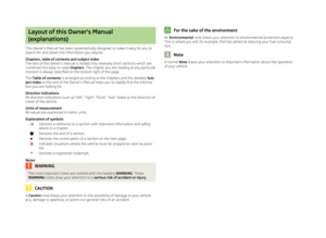 2
2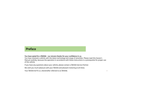 3
3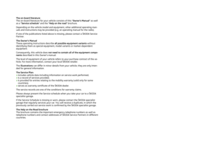 4
4 5
5 6
6 7
7 8
8 9
9 10
10 11
11 12
12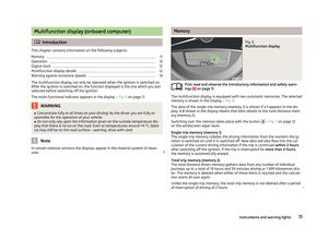 13
13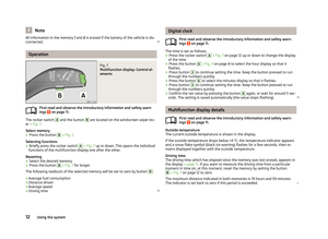 14
14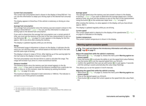 15
15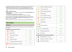 16
16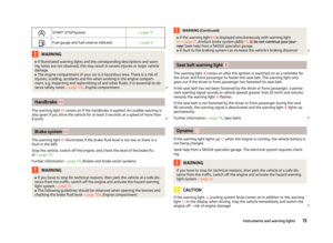 17
17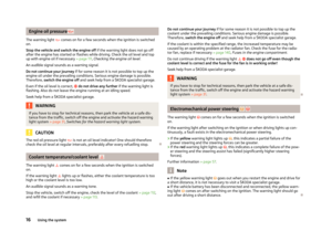 18
18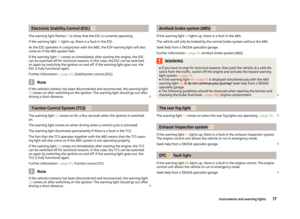 19
19 20
20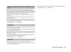 21
21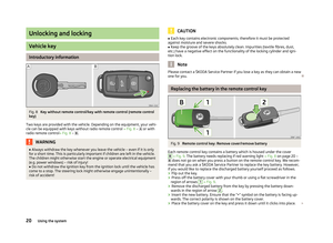 22
22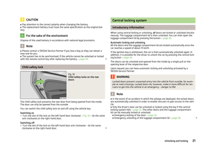 23
23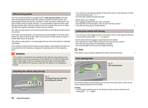 24
24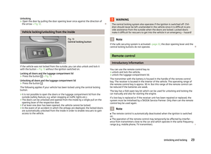 25
25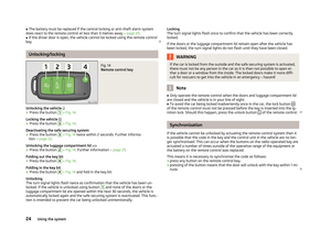 26
26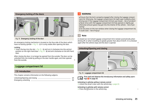 27
27 28
28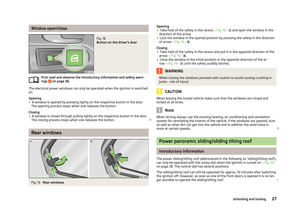 29
29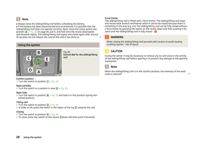 30
30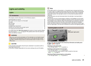 31
31 32
32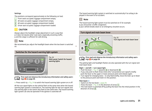 33
33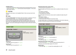 34
34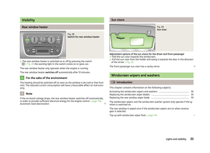 35
35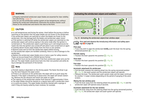 36
36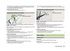 37
37 38
38 39
39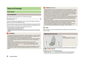 40
40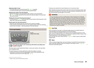 41
41 42
42 43
43 44
44 45
45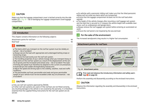 46
46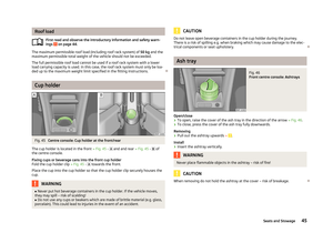 47
47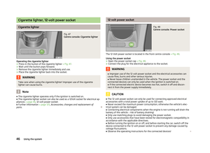 48
48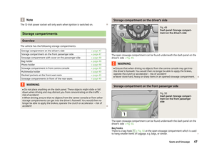 49
49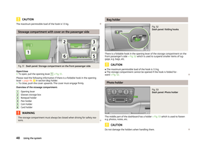 50
50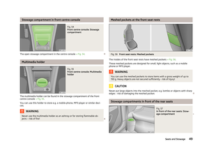 51
51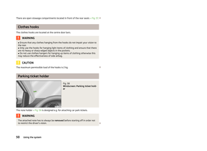 52
52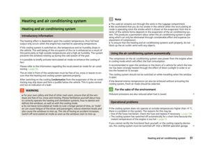 53
53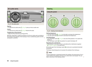 54
54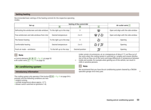 55
55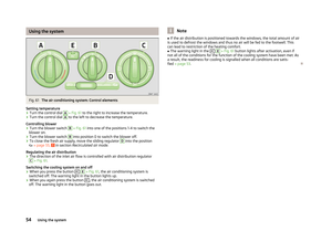 56
56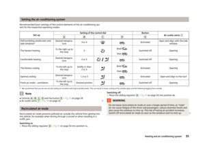 57
57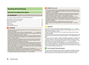 58
58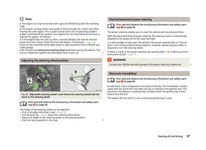 59
59 60
60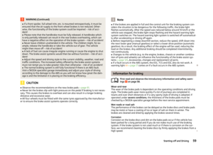 61
61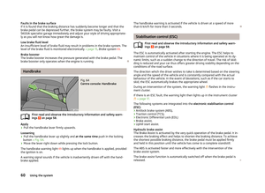 62
62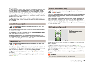 63
63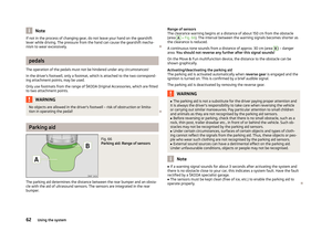 64
64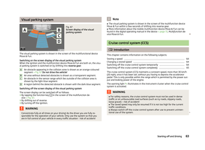 65
65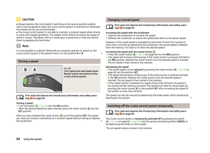 66
66 67
67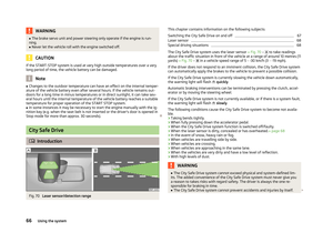 68
68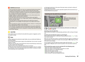 69
69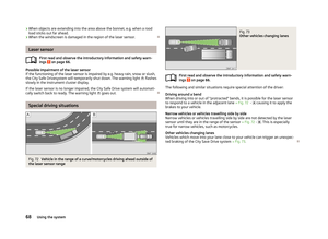 70
70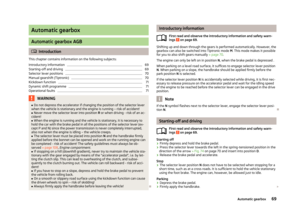 71
71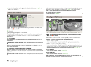 72
72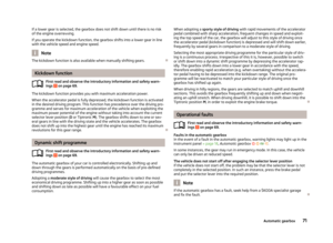 73
73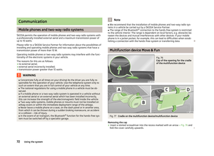 74
74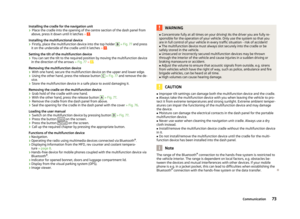 75
75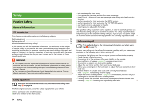 76
76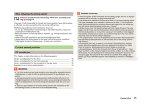 77
77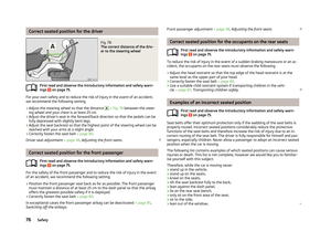 78
78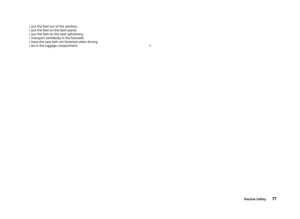 79
79 80
80 81
81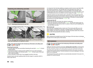 82
82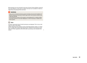 83
83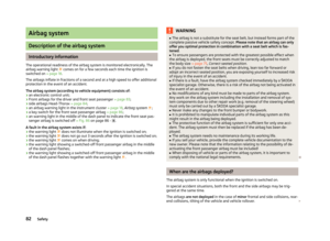 84
84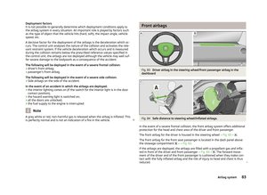 85
85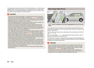 86
86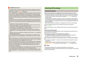 87
87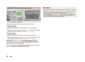 88
88 89
89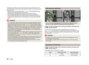 90
90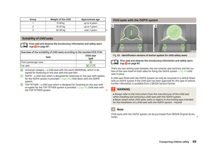 91
91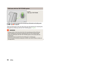 92
92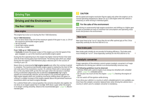 93
93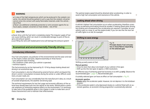 94
94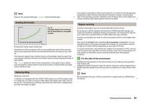 95
95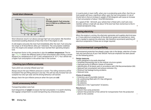 96
96 97
97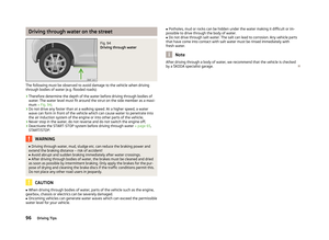 98
98 99
99 100
100 101
101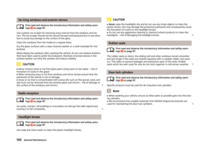 102
102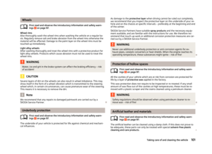 103
103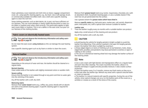 104
104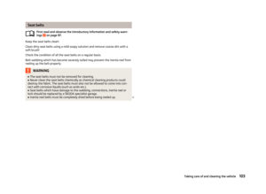 105
105 106
106 107
107 108
108 109
109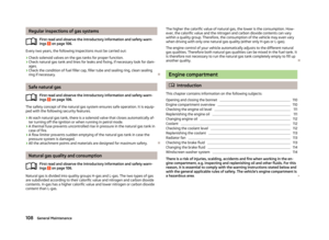 110
110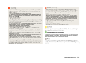 111
111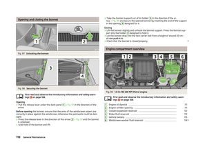 112
112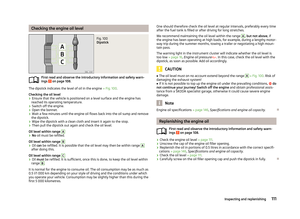 113
113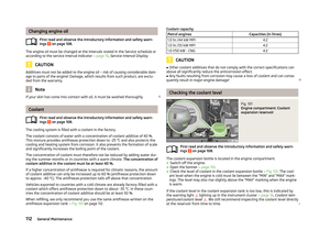 114
114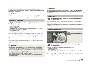 115
115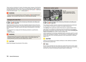 116
116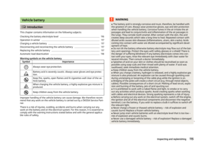 117
117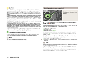 118
118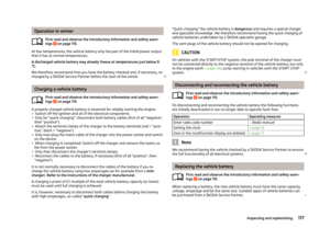 119
119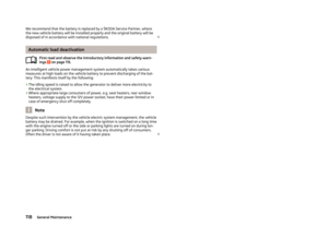 120
120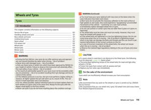 121
121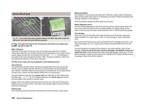 122
122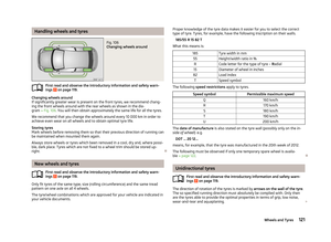 123
123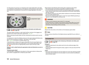 124
124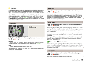 125
125 126
126 127
127 128
128 129
129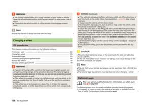 130
130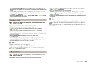 131
131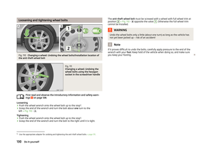 132
132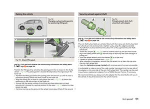 133
133 134
134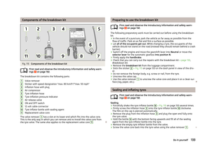 135
135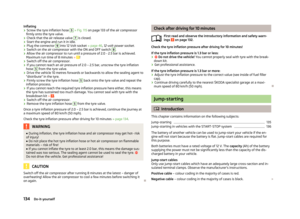 136
136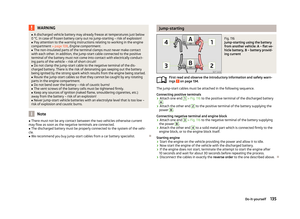 137
137 138
138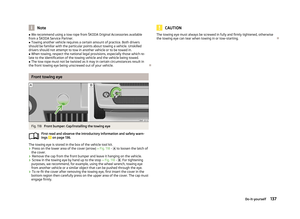 139
139 140
140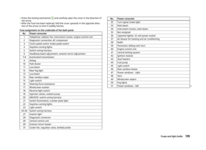 141
141 142
142 143
143 144
144 145
145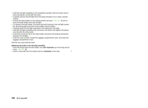 146
146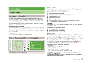 147
147 148
148 149
149 150
150 151
151 152
152 153
153 154
154 155
155 156
156