Page 137 of 157

WARNING
■ A discharged vehicle battery may already freeze at temperatures just below
0 °C. In case of frozen battery carry out no jump-starting – risk of explosion!
■ Pay attention to the warning instructions relating to working in the engine
compartment » page 108, Engine compartment .
■ The non-insulated parts of the terminal clamps must never make contact
with each other. In addition, the jump-start cable connected to the positive
terminal of the battery must not come into contact with electrically conduct-
ing parts of the vehicle – risk of short circuit! ■ Do not clamp the jump-start cable to the negative terminal of the dis-
charged battery. There is the risk of detonating gas seeping out the battery
being ignited by the strong spark which results from the engine being started. ■ Route the jump-start cables so that they cannot be caught by any rotating
parts in the engine compartment. ■ Do not bend over the battery – risk of caustic burns!
■ The vent screws of the battery cells must be tightened firmly.
■ Keep any sources of ignition (naked flame, smouldering cigarettes, etc.)
away from the battery – risk of an explosion!
■ Never jump-start vehicle batteries with an electrolyte level that is too low –
risk of explosion and caustic burns. Note
■ There must not be any contact between the two vehicles otherwise current
may flow as soon as the negative terminals are connected. ■ The discharged battery must be properly connected to the system of the vehi-
cle. ■ We recommend you buy jump-start cables from a car battery specialist. Ð Jump-starting
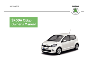
Fig. 116
Jump-starting using the battery
from another vehicle: A – flat ve-
hicle battery, B – battery provid-
ing current
First read and observe the introductory information and safety warn-
ings on page 134.
The jump-start cables must be attached in the following sequence.
Connecting positive terminals
› Attach one end 1
» Fig. 116
to the positive terminal of the discharged battery A
.
› Attach the other end 2
to the positive terminal of the battery supplying the
power B
.
Connecting negative terminal and engine block
› Attach one end 3
»
Fig. 116
to the negative terminal of the battery supplying
the power B
.
› Attach the other end 4
to a solid metal part which is connected firmly to the
engine block, or to the engine block itself.
Starting engine
› Start the engine on the vehicle providing the power and allow it to idle.
› Now start the engine of the vehicle with the discharged battery.
› If the engine does not start, terminate the attempt to start the engine after
10 seconds and wait for about 30 seconds before repeating the process.
› Disconnect the cables in exactly the
reverse order to the one described above. Ð
ä
135
Do-it-yourself
Page 138 of 157

Jump-starting in vehicles with the START-STOP system
Fig. 117
Engine compartment: Engine
earth
First read and observe the introductory information and safety warn-
ings on page 134.
On vehicles with the START-STOP system, the jump-start cable of the charger
must never be connected directly to the negative pole of the vehicle battery, but
only to the engine earth
» Fig. 117. ÐTowing the vehicle
ä
Introduction
This chapter contains information on the following subjects:
Front towing eye 137
Vehicles with manual transmission can be towed in with a tow bar or a tow rope
or with the front or rear wheels raised.
Vehicles with automated transmission can be towed with a tow bar or a tow rope
or with the front wheels raised. If the vehicle is raised at rear, the automatic gear-
box is damaged!
A tow bar is the safest way of towing a vehicle and also minimises any shocks.
Only use a tow rope if a suitable tow bar is not available.
When towing, the following guidelines must be observed.
Driver of the tow vehicle
› Release the clutch particularly gently when starting off or depress the accelera-
tor particularly gently if the vehicle is fitted with an automated transmission.
ä
›
On vehicles with a manual transmission, only push down on the accelerator
pedal once the rope is taught.
The maximum towing speed is 50 km/h.
Driver of the towed vehicle
› Switch on the ignition so that the steering wheel is not blocked and so that the
turn signal lights, horn, windscreen wipers and windscreen washer system can
be switched on.
› Take the vehicle out of gear or move the selector lever into position
N if the
vehicle is fitted with an automated transmission.
Please note that the brake servo unit and power steering only operate if the en-
gine is running. If the engine is not running, significantly more physical force is re-
quired to depress the brake pedal and steer the vehicle.
If using a tow rope, ensure that it is always kept taught. CAUTION
■ Do not tow start the engine - danger of damaging the engine! On vehicles with
a catalytic converter, unburnt fuel may get into the catalytic converter where it
may ignite. This in turn may damage or destroy the catalytic converter. The bat-
tery from another vehicle can be used as a jump-start aid » page 134, Jump-start-
ing .
■ If the gearbox of your vehicle no longer contains any oil because of a defect,
your vehicle must only be towed in with the driven wheels raised clear of the
ground, or on a special vehicle transporter or trailer.
■ The vehicle must be transported on a special vehicle or trailer if it is not possible
to tow in the vehicle in the way described or if the towing distance is greater than
50 km. ■ To protect both vehicles when tow-starting or towing, the tow rope should be
elastic. Thus one should only use plastic fibre rope or a rope made out of a simi-
larly elastic material.
■ One should be constantly vigilant not to allow impermissibly high towing forces
or jerky loadings. There is always a risk of excessive stresses and damage result-
ing at the points to which you attach the tow rope or tow bar when you attempt
to tow a vehicle which is not standing on a paved road.
■ Attach the tow rope or the tow bar only to the towing eye » page 137. £
136 Do-it-yourself
Page 139 of 157

Note
■ We recommend using a tow rope from ŠKODA Original Accessories available
from a ŠKODA Service Partner. ■ Towing another vehicle requires a certain amount of practice. Both drivers
should be familiar with the particular points about towing a vehicle. Unskilled
drivers should not attempt to tow in another vehicle or to be towed in. ■ When towing, respect the national legal provisions, especially those which re-
late to the identification of the towing vehicle and the vehicle being towed. ■ The tow rope must not be twisted as it may in certain circumstances result in
the front towing eye being unscrewed out of your vehicle. ÐFront towing eye
Fig. 118
Front bumper: Cap/installing the towing eye
First read and observe the introductory information and safety warn-
ings on page 136.
The towing eye is stored in the box of the vehicle tool kit.
› Press on the lower area of the cover (arrow)
» Fig. 118 -
to loosen the latch of
the cover.
› Remove the cap from the front bumper and leave it hanging on the vehicle.
› Screw in the towing eye by hand up to the stop
» Fig. 118 - . For tightening
purposes, we recommend, for example, using the wheel wrench, towing eye
from another vehicle or a similar object that can be pushed through the eye.
› To re-fit the cover after removing the towing eye, first insert the cover in the
bottom region then carefully press on the upper area of the cover. The cap must
engage firmly.
ä CAUTION
The towing eye must always be screwed in fully and firmly tightened, otherwise
the towing eye can tear when towing in or tow-starting. Ð 137
Do-it-yourself
Page 140 of 157

Fuses and light bulbs
Fuses
ä
Introduction
This chapter contains information on the following subjects:
Fuses on the underside of the dash panel 138
Fuses in the engine compartment 140
Fuses in the dash panel 140
Individual electrical circuits are protected by fuses.
› Before replacing a fuse, switch off the ignition and the appropriate consumer
› Find out which fuse belongs to the component that is not operat-
ing » page 138, Fuses on the underside of the dash panel , » page 140, Fuses
in the engine compartment , or »
page 140, Fuses in the dash panel .
› Take the plastic clip out of its fixture in the cover of the fuse box, place it on the
relevant fuse and pull it out.
› A blown fuses is recognisable by the molten metal strip. Replace the faulty fuse
with a new one of the
same amperage.
Colour coding of fuses Colour Maximum amperage
purple 3
light brown 5
brown 7.5
red 10
blue 15
yellow 20
white 25
green 30
orange 40 WARNING
Always read and observe the warnings before completing any work in the en-
gine compartment » page 108, Engine compartment . CAUTION
■ Never “repair” fuses and also do not replace them with a fuse of a higher am-
perage - risk of fire! This may also cause damage at another part of the electrical
system.
■ Have the electrical system checked as quickly as possible by a ŠKODA specialist
garage if a newly inserted fuse blows again after a short time. Note
■ We recommend always carrying replacement fuses in the vehicle. A box of re-
placement fuses can be purchased from
ŠKODA Original Accessories.
■ Multiple fuses may exist for a single power consuming device.
■ Multiple power consuming devices can share a single fuse. Ð Fuses on the underside of the dash panel
Fig. 119
Underside of the dash panel: Fuse box/schematic diagram of the
fuse box
First read and observe the introductory information and safety warn-
ings on page 138.
The fuses are located underneath the steering wheel on the underside of the
dash panel » Fig. 119. £
ä
138 Do-it-yourself
Page 141 of 157

›
Press the locking mechanism 1
and carefully open the cover in the direction of
the arrow.
› After the fuse has been replaced, fold the cover upwards in the opposite direc-
tion of the arrow so that it audibly latches.
Fuse assignment on the underside of the dash panel No. Power consumer
1 Telephone, radiator fan, instrument cluster, engine control unit
2 Diagnostic connection, AC compressor
3 Clutch pedal switch, brake pedal switch
4 Daytime running lights 5 Switch wiring harness
6 Headlamp beam adjustment, exterior mirror adjustment
7-8 Automated transmission 9 Airbag
10 Park Assist 11 Low beam
12 Rear fog light
13 Low beam
14 Rear window wiper 15 Light switch
16 Steering force assistance 17 Windscreen washer
18 Reverse light switch 19 Injection valves, coolant pump
20 ABS/ESP, switch wiring harness 21 Switch illumination, number plate light
22 Daytime running lights
23 Light switch
24-26 Switch wiring harness 27 Interior light
28 Diagnostic connector 29 Central control unit
30 Exterior mirror heater 31 Cooler fan, regulator valve, lambda probe No. Power consumer
32 Turn signal, brake light
33 Main beam
34 Instrument cluster, main beam 35 Not assigned
36 Cigarette lighter, 12-volt power socket 37 Air blower for heating and air conditioning
38 Radio 39 Panoramic sliding roof, horn
40 Engine control unit 41 Central locking system
42 Ignition module
43 Seat heaters
44 Fuel pump 45 Light switch
46 Rear window heater 47 Power windows - right
48 Horn 49 Windscreen wipers50 Fog lights 51 Power windows - left Ð
139
Fuses and light bulbs
Page 142 of 157

Fuses in the engine compartment
Fig. 120
Engine compartment: Distribution board cover/fuses
First read and observe the introductory information and safety warn-
ings on page 138.
The fuses are located underneath a cover next to the vehicle battery
» Fig. 120.
› Press together the interlocks of the cover A
simultaneously and press the cov-
er upwards in the direction of the arrow.
› After the fuse has been replaced, place the cover on the fuse box and fold up-
wards in the opposite direction of the arrow so that it audibly latches.
Fuse assignment in engine compartment No. Power consumer
S1 ABS/ESP
S2 Radiator fan
S3 Battery management, control unit for radiator fan
S4 ABS/ESP S5 Central control unit
S6 Ignition lock, starter Ð
ä Fuses in the dash panel
Fig. 121
On the driver's side of the dash panel: Fuse box cover/Schematic di-
agram of the fuse box
First read and observe the introductory information and safety warn-
ings on page 138.
The fuses are located on the left-hand side of the dashboard behind a cover on
vehicles with the
START STOP system.
› Insert a suitably flat object, e.g. a screwdriver, into the slot in the region of the
arrow » Fig. 121, carefully prise out the cover and remove.
› After the fuse has been replaced, place the cover on the fuse box and press it
until it audibly latches.
Fuse assignment in the dash panel No. Power consumer
1 ABS/ESP
2 Instrument cluster
3 Radio, diagnosis
4 DC-DC voltage converter, starter relay 5 Not assigned
6 Air blower for air conditioning/heating 7 Control unit for the AC system
8 Not assigned 9 Right light
10 Left light £ ä
140 Do-it-yourself
Page 143 of 157

No. Power consumer
11 Starter
12 DC-DC voltage converter Ð
Bulbs
ä
Introduction
This chapter contains information on the following subjects:
Headlights 141
Changing the light bulb for side repeater turn signal lights 142
Changing light bulbs for fog lights 142
Changing the bulb for the licence plate light 143
Tail lamp assembly 143
Some manual skills are required to change a bulb. For this reason, if uncertain, we
recommend that bulbs are replaced by a ŠKODA specialist garage or other expert
help is sought.
› Switch off the ignition and all of the lights before replacing a bulb.
› Faulty bulbs must only be replaced with the same type of bulbs. The designa-
tion is located on the light socket or the glass bulb.
› A stowage compartment for replacement bulbs is located in a plastic box in the
spare wheel or underneath the floor covering in the luggage compartment. WARNING
■ Accidents can be caused if the road in front of the vehicle is not sufficiently
illuminated and the vehicle cannot or can only be seen with difficulty by other
road users.
■ Always read and observe the warnings before completing any work in the
engine compartment » page 108, Engine compartment .
■ The H4 bulb is under pressure and may explode during a lamp replacement -
risk of injury! We therefore recommended wearing gloves and safety glasses
when changing a bulb. CAUTION
■ Do not take hold of the glass bulb with naked fingers (even the smallest
amount of dirt reduces the working life of the light bulb). Use a clean cloth, nap-
kin, or similar. ■ When removing and installing the number plate light and tail light make sure
that the paintwork of the vehicle and the tail light are not damaged. Note
■ This Owner's Manual only describes the replacement of bulbs where it is possi-
ble to replace the bulbs on your own without any complications arising. Other
light bulbs should be changed by a
ŠKODA specialist garage.
■ We recommend that a box of replacement bulbs be always carried in the vehi-
cle. Replacement bulbs can be purchased from
ŠKODAOriginal Accessories.
■ We recommend that the headlight settings are checked by a ŠKODA specialist
garage after replacing a bulb in the main or low beam.
■ LED diodes should be changed by a specialist ŠKODA garage. Ð Headlights
Fig. 122
Left headlight - engine compartment: Arrangement/lamp removal
First read and observe the introductory information and safety warn-
ings on page 141.
Open the bonnet before replacing the bulb in the front headlight
» page 110,
Opening and closing the bonnet .
Bulb arrangement in the front headlight A
- Front turn signal light
» Fig. 122 £
ä
141
Fuses and light bulbs
Page 144 of 157

B
- Low beam and main beam
C
- Parking and daytime running light
Changing the bulb for the front turn signal light
› Turn the bulb holder A
» Fig. 122anti-clockwise
up to the stop and remove.
› Push the faulty bulb into the holder, turn
in anti-clockwise up to the stop and
remove.
› Insert a new bulb into the socket and turn
clockwise to the stop.
› Insert the lamp holder with the new bulb into the headlamp and turn it
clock-
wise until it stops.
Replacing the bulb for low beam and main beam
› Remove the connector on the bulb B
» Fig. 122.
› Remove the rubber cover.
› Press the circlip D
in the direction of the headlamp and then unhook in the di-
rection of the arrow.
› Remove the light bulb and insert a new light bulb in such a way that the fixing
lugs of the light bulb socket fit into the recesses at the headlight.
Installation is carried out in the reverse order.
Replacing the bulb for the front parking light and daylight running light
› Turn the bulb holder C
» Fig. 122anti-clockwise
up to the stop and remove.
› Remove the faulty bulb from the socket.
› Insert a new bulb into the socket.
› Insert the lamp holder with the new bulb into the headlamp and turn it
clock-
wise until it stops. ÐChanging the light bulb for side repeater turn signal lights
Fig. 123
Right side: Replacing the bulb for the turn signal light First read and observe the introductory information and safety warn-
ings on page 141.
›
Push the side repeater turn signal light in the direction of the arrow 1
» Fig. 123.
› Prise the turn signal light from the body in the direction of the arrow 2
.
› Remove the bulb holder 3
in the direction of arrow.
› Remove the faulty bulb from the socket.
› Insert a new bulb into the socket.
› Replace the bulb holder.
› Set the side repeater turn signal light with the side facing the rear of the vehi-
cle in the body and lightly press it until the spring on the other side of the side
repeater turn signal light latches. Ð Changing light bulbs for fog lights
Fig. 124
Front wheel houe: Changing light bulbs for fog lights
First read and observe the introductory information and safety warn-
ings on page 141.
›
Unscrew the two attachment bolts on the wheel house trim with the screw-
driver » page 127 , Vehicle tool kit (arrows) » Fig. 124.
› Undo the expanding rivet A
»
Fig. 124
below on the wheel house trim with a
flat, dull object, such as a coin, remove.
› Fold the wheel house trim to the side, remove the connector 1
.
› Turn the lamp holder (bulb set- holder including bulb)
anti-clockwise
as far as
the stop, remove.
› Insert the lamp holder with the new bulb into the headlamp and turn it
clock-
wise as far as the stop; insert the connector until it latches securely.
› Fold the wheel house trim back.
£
ä
ä
142 Do-it-yourself
 1
1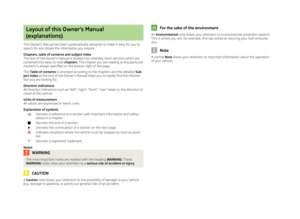 2
2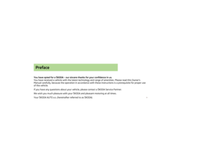 3
3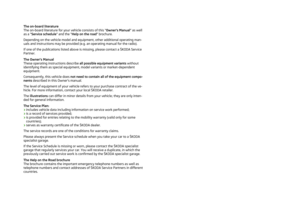 4
4 5
5 6
6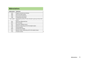 7
7 8
8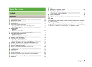 9
9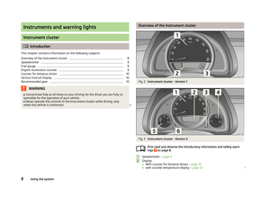 10
10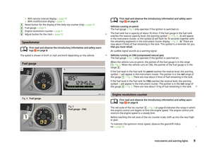 11
11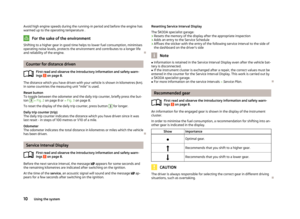 12
12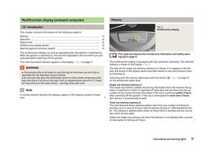 13
13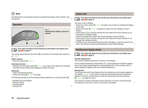 14
14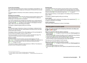 15
15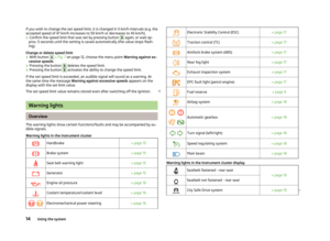 16
16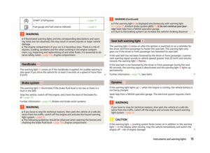 17
17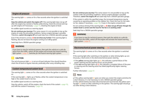 18
18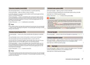 19
19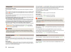 20
20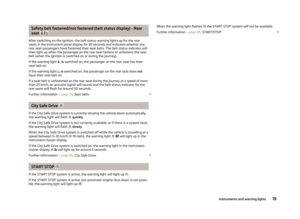 21
21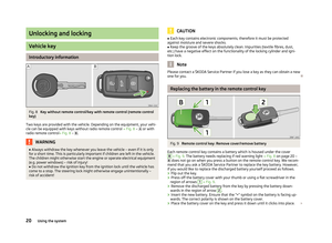 22
22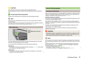 23
23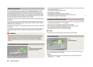 24
24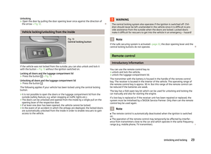 25
25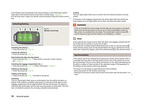 26
26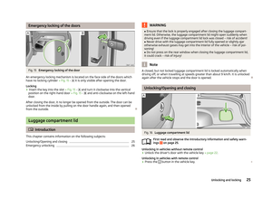 27
27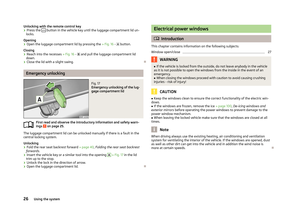 28
28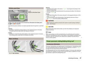 29
29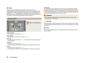 30
30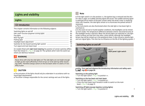 31
31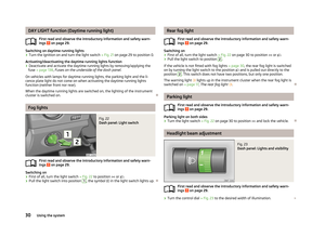 32
32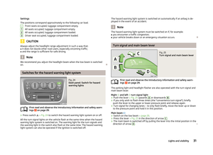 33
33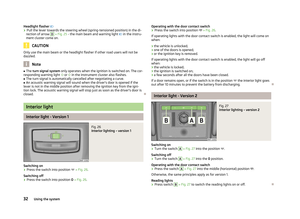 34
34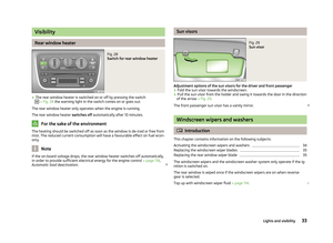 35
35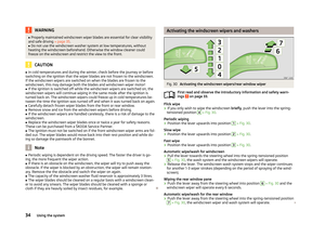 36
36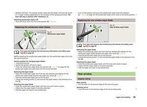 37
37 38
38 39
39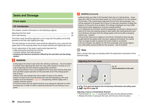 40
40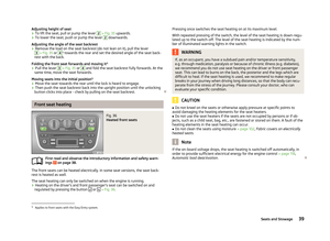 41
41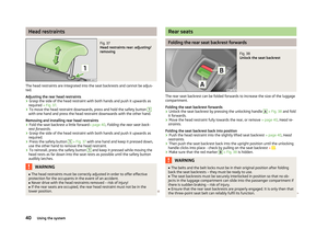 42
42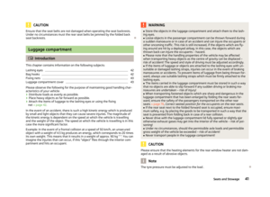 43
43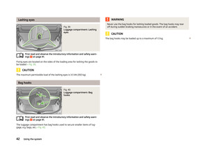 44
44 45
45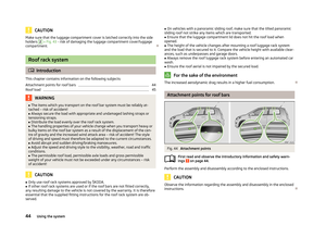 46
46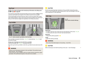 47
47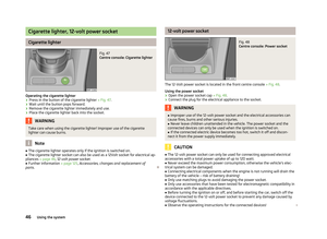 48
48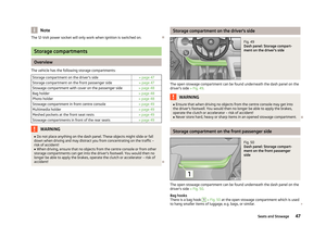 49
49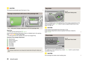 50
50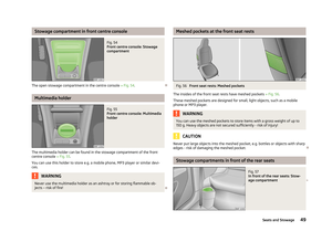 51
51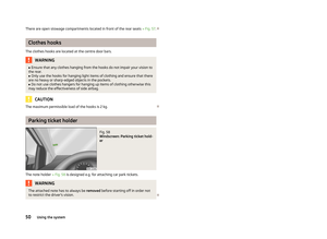 52
52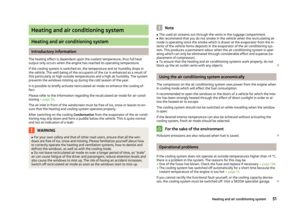 53
53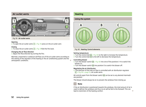 54
54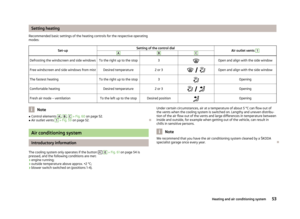 55
55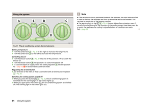 56
56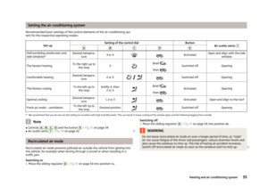 57
57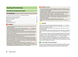 58
58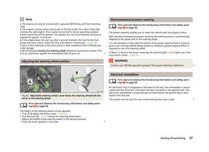 59
59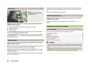 60
60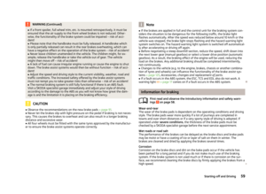 61
61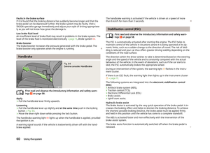 62
62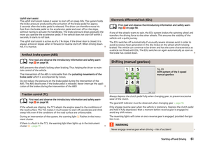 63
63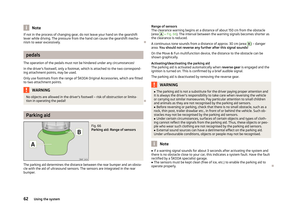 64
64 65
65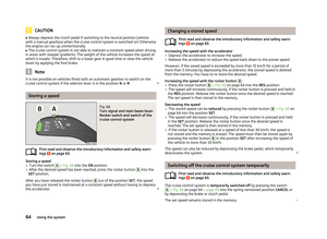 66
66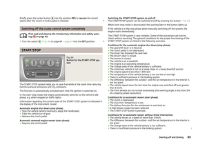 67
67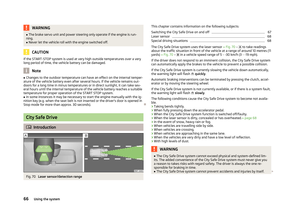 68
68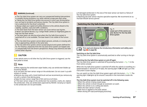 69
69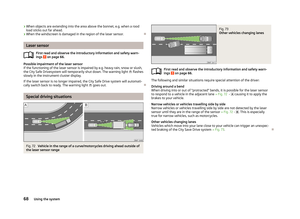 70
70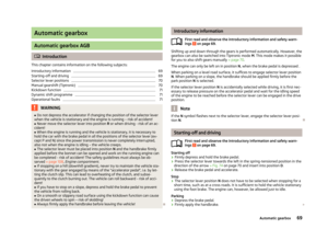 71
71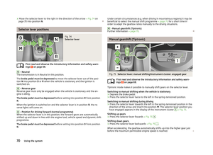 72
72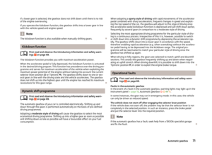 73
73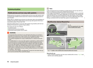 74
74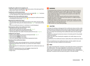 75
75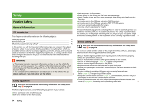 76
76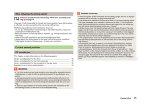 77
77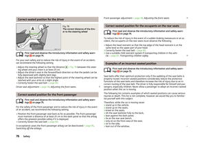 78
78 79
79 80
80 81
81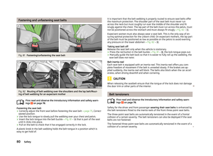 82
82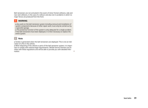 83
83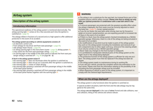 84
84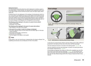 85
85 86
86 87
87 88
88 89
89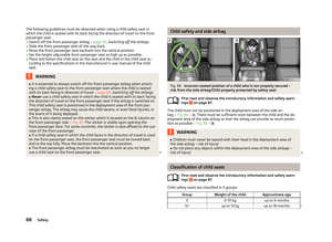 90
90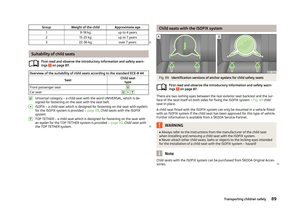 91
91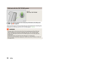 92
92 93
93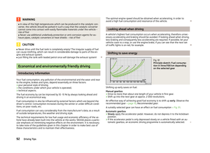 94
94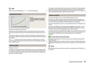 95
95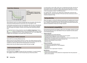 96
96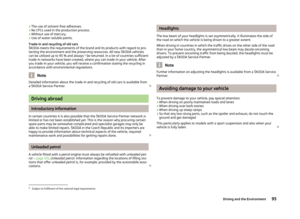 97
97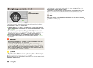 98
98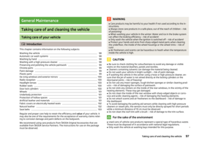 99
99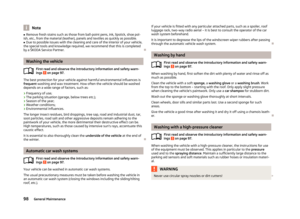 100
100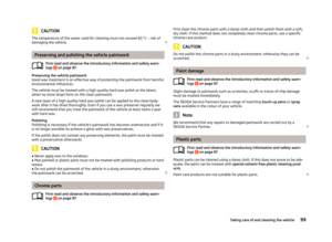 101
101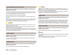 102
102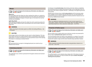 103
103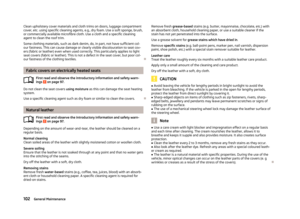 104
104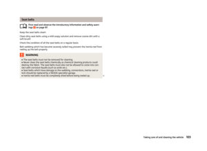 105
105 106
106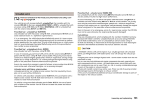 107
107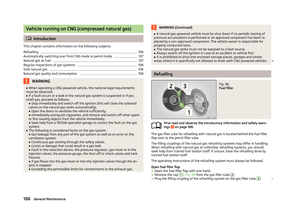 108
108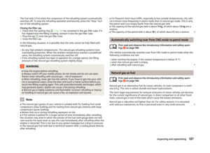 109
109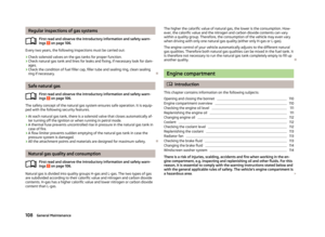 110
110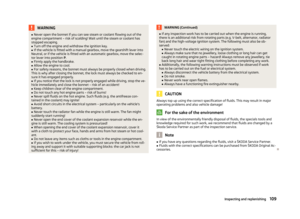 111
111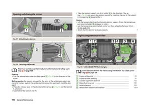 112
112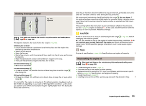 113
113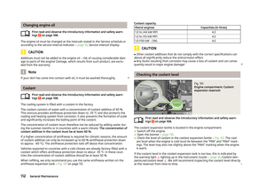 114
114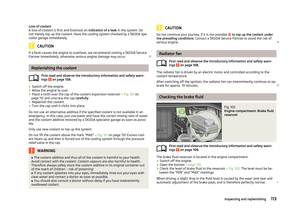 115
115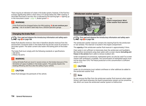 116
116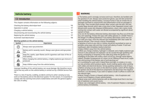 117
117 118
118 119
119 120
120 121
121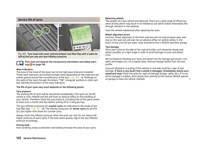 122
122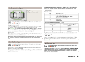 123
123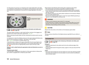 124
124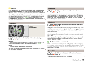 125
125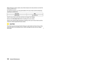 126
126 127
127 128
128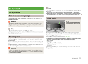 129
129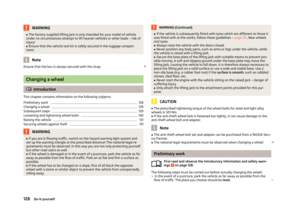 130
130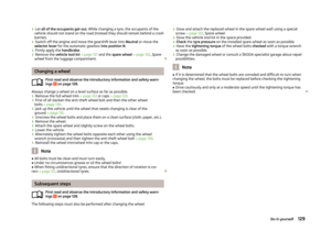 131
131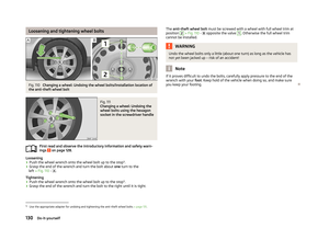 132
132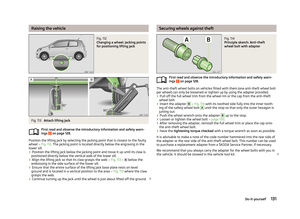 133
133 134
134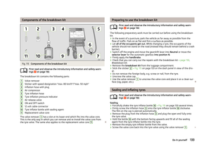 135
135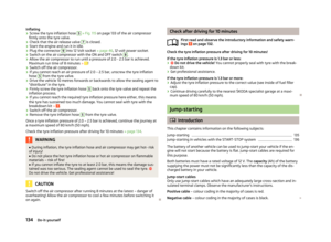 136
136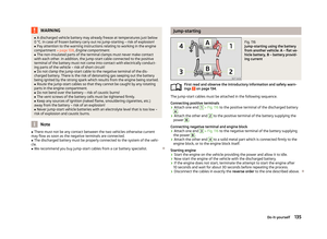 137
137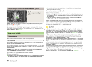 138
138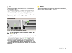 139
139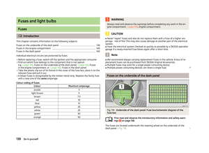 140
140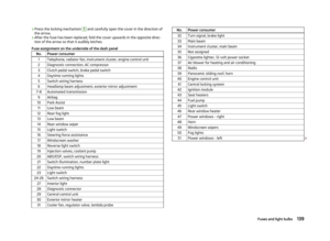 141
141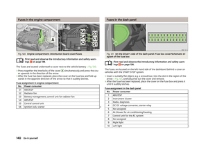 142
142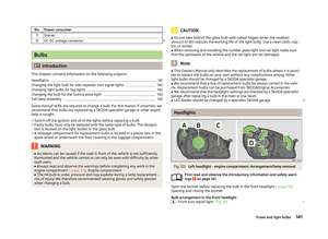 143
143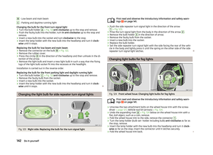 144
144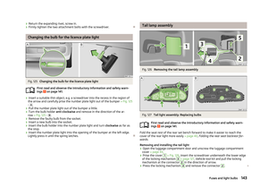 145
145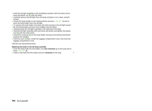 146
146 147
147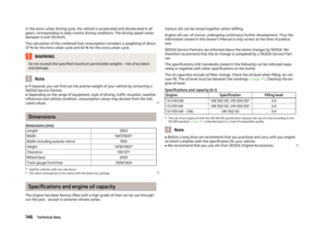 148
148 149
149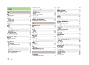 150
150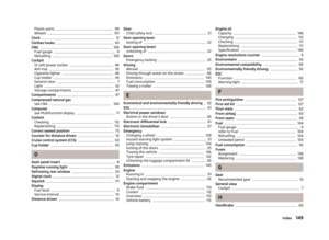 151
151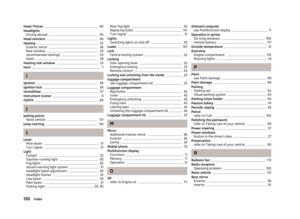 152
152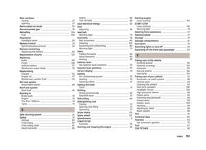 153
153 154
154 155
155 156
156