Page 129 of 157

Do-it-yourself
Do-it-yourself
First-aid kit and warning triangle
The warning triangle can be stowed away underneath the floor covering of the
luggage compartment. WARNING
The first-aid kit and warning triangle must always be secured safely so that
they do not come loose when making an emergency braking or in a vehicle
collision which could cause injuries to occupants. Note
■ Pay attention to the expiration date of the first-aid kit.
■ We recommend using a first-aid box from ŠKODA Original Accessories available
from a ŠKODA Service Partner. ÐFire extinguisher
The fire extinguisher is located at a holder in the foot well in front of the front
passenger seat.
Please read carefully the instructions which are attached to the fire extinguish-
er.
The fire extinguisher must be checked by an authorised person on an annual ba-
sis (the national legal provisions must be observed). WARNING
The fire extinguisher must always be secured safely so that they do not come
loose when making an emergency braking or in a vehicle collision which could
cause injuries to occupants. Note
■ The fire extinguisher must comply with the relevant applicable national legal re-
quirements. ■ Pay attention to the expiration date of the fire extinguisher. If the fire extin-
guisher is used after the expiration date, its proper function is no longer assured.
■ The fire extinguisher is part of the scope of delivery in certain countries only. Ð Vehicle tool kit
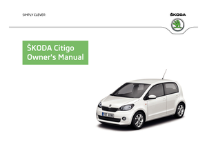
Fig. 109
Luggage compartment: Storage
compartment for vehicle tool kit
The vehicle tool kit and the lifting jack with sticker are housed in a box in the
spare wheel or in the compartment for the spare wheel underneath the floor cov-
ering in the luggage compartment.
Raise the floor covering at the recess (arrow) » Fig. 109.
The vehicle tool kit contains the following parts (depending on equipment fitted):
› Wire clamp for removing the full wheel trims or wheel bolt covers;
› wheel wrench;
› towing eye;
› Adapter for anti-theft wheel bolts;
› Replacement bulb set;
› Screwdriver.
Before placing the lifting jack back into its storage area, screw in the arm of the
lifting jack fully. £
127
Do-it-yourself
Page 130 of 157

WARNING
■ The factory-supplied lifting jack is only intended for your model of vehicle.
Under no circumstances attempt to lift heavier vehicles or other loads – risk of
injury!
■ Ensure that the vehicle tool kit is safely secured in the luggage compart-
ment. Note
Ensure that the box is always secured with the strap. ÐChanging a wheel
ä
Introduction
This chapter contains information on the following subjects:
Preliminary work 128
Changing a wheel 129
Subsequent steps 129
Loosening and tightening wheel bolts 130
Raising the vehicle 131
Securing wheels against theft 131
WARNING
■ If you are in flowing traffic, switch on the hazard warning light system and
set up the warning triangle at the prescribed distance! The national legal re-
quirements must be observed. In this way you are not only protecting yourself
but other road users as well.
■ If the wheel is damaged or in the event of a puncture, park the vehicle as far
away as possible from the flow of traffic. Park on as flat and firm a surface as
possible. ■ If the wheel has to be changed on a slope, first of all block the opposite
wheel with a stone or similar object to prevent the vehicle from unexpectedly
rolling away. WARNING (Continued)
■ If the vehicle is subsequently fitted with tyres which are different to those it
was fitted with at the works, follow these guidelines » page 121, New wheels
and tyres.
■ Always raise the vehicle with the doors closed.
■ Never position any body parts, such as arms or legs under the vehicle, while
the vehicle is raised with a lifting jack. ■ Secure the base plate of the lifting jack with suitable means to prevent pos-
sible moving. A soft and slippery ground under the base plate may move the
lifting jack, causing the vehicle to fall down. It is therefore always necessary to
place the lifting jack on a solid surface or use a wide and stable base. Use a
non-slip base (e.g. a rubber foot mat) if the surface is smooth, such as cobbled
stones, tiled floor, etc.
■ Never start the engine with the vehicle sitting on the raised jack – danger of
suffering injury.
■ Only attach the lifting jack to the attachment points provided for this pur-
pose. CAUTION
■ The prescribed tightening torque of the wheel bolts for steel and light alloy
wheels is 120
Nm.
■ If the anti-theft wheel bolt is fastened too tightly, it can cause damage to the
anti-theft wheel bolt and adapter. Note
■ The anti-theft wheel bolt set and adapter can be purchased from a
ŠKODA Serv-
ice Partner. ■ The national legal requirements must be observed when changing a wheel. Ð Preliminary work
First read and observe the introductory information and safety warn-
ings on page 128.
The following steps must be carried out before actually changing the wheel:
›
In the event of a puncture, park the vehicle as far away as possible from the
flow of traffic. The place you choose should be level. £
ä
128 Do-it-yourself
Page 131 of 157
.
› Switch off the engine a")
›
Let all of the occupants get out.
While changing a tyre, the occupants of the
vehicle should not stand on the road (instead they should remain behind a crash
barrier).
› Switch off the engine and move the gearshift lever into
Neutral or move the
selector lever for the automatic gearbox into position N.
› Firmly apply the
handbrake.
› Remove the vehicle tool kit
» page 127 and the spare wheel » page 122, Spare
wheel from the luggage compartment. ÐChanging a wheel
First read and observe the introductory information and safety warn-
ings on page 128.
Always change a wheel on a level surface as far as possible.
›
Remove the full wheel trim
» page 122 or caps »
page 123.
› First of all slacken the anti-theft wheel bolt and then the other wheel
bolts » page 130.
› Jack up the vehicle until the wheel that needs changing is clear of the
ground » page 131 .
› Unscrew the wheel bolts and place them on a clean surface (cloth, paper, etc.).
› Remove the wheel.
› Attach the spare wheel and slightly screw on the wheel bolts.
› Lower the vehicle.
› Alternately tighten the wheel bolts opposite each other using the wheel
wrench (crosswise) and then tighten the anti-theft wheel bolt » page 130.
› Reinstall the wheel trim/wheel trim cap or the caps. Note
■ All bolts must be clean and must turn easily.
■ Under no circumstances grease or oil the wheel bolts!
■ When fitting unidirectional tyres, ensure that the direction of rotation is cor-
rect »
page 121, Unidirectional tyres . ÐSubsequent steps
First read and observe the introductory information and safety warn-
ings on page 128.
The following steps must also be performed after changing the wheel.ä
ä ›
Stow and attach the replaced wheel in the spare wheel well using a special
screw » page 122, Spare wheel.
› Stow the vehicle tool kit in the space provided.
› Check
the tyre pressure
on the installed spare wheel as soon as possible.
› Have the
tightening torque of the wheel bolts checked with a torque wrench
as soon as possible.
› Change the damaged wheel or consult a ŠKODA specialist garage about repair
possibilities. Note
■ If it is determined that the wheel bolts are corroded and difficult to turn when
changing the wheel, the bolts must be replaced before checking the tightening
torque. ■ Drive cautiously and only at a moderate speed until the tightening torque has
been checked. Ð
129
Do-it-yourself
Page 132 of 157

Loosening and tightening wheel bolts
Fig. 110
Changing a wheel: Undoing the wheel bolts/installation location of
the anti-theft wheel bolt Fig. 111
Changing a wheel: Undoing the
wheel bolts using the hexagon
socket in the screwdriver handle
First read and observe the introductory information and safety warn-
ings on page 128.
Loosening
›
Push the wheel wrench onto the wheel bolt up to the stop 1)
.
› Grasp the end of the wrench and turn the bolt about
one turn to the
left » Fig. 110 - .
Tightening
› Push the wheel wrench onto the wheel bolt up to the stop 1)
.
› Grasp the end of the wrench and turn the bolt to the right until it is tight.
ä The anti-theft wheel bolt
must be screwed with a wheel with full wheel trim at
position 2
» Fig. 110 - opposite the valve 1
. Otherwise the full wheel trim
cannot be installed. WARNING
Undo the wheel bolts only a little (about one turn) as long as the vehicle has
not yet been jacked up – risk of an accident! Note
If it proves difficult to undo the bolts, carefully apply pressure to the end of the
wrench with your foot. Keep hold of the vehicle when doing so, and make sure
you keep your footing. Ð1)
Use the appropriate adapter for undoing and tightening the anti-theft wheel bolts » page 131.
130 Do-it-yourself
Page 133 of 157

Raising the vehicle
Fig. 112
Changing a wheel: Jacking points
for positioning lifting jack Fig. 113
Attach lifting jack
First read and observe the introductory information and safety warn-
ings on page 128.
Position the lifting jack by selecting the jacking point that is closest to the faulty
wheel
» Fig. 112. The jacking point is located directly below the engraving in the
lower sill.
› Position the lifting jack below the jacking point and move it up until its claw is
positioned directly below the vertical web of the lower sill.
› Align the lifting jack so that its claw grasps the web
» Fig. 113 –
below the
embossing in the side surface of the lower sill.
› Ensure that the entire surface of the lifting jack base plate rests on level
ground and is located in a vertical position to the area » Fig. 113 where the claw
grasps the web.
› Continue turning up the jack until the wheel is just about lifted off the ground. Ð
ä Securing wheels against theft
Fig. 114
Principle sketch: Anti-theft
wheel bolt with adapter
First read and observe the introductory information and safety warn-
ings on page 128.
The anti-theft wheel bolts on vehicles fitted with them (one anti-theft wheel bolt
per wheel) can only be loosened or tighten up by using the adapter provided.
›
Pull off the full wheel trim from the wheel rim or the cap from the anti-theft
wheel bolt.
› Insert the adapter B
» Fig. 114
with its toothed side fully into the inner tooth-
ing of the safety wheel bolt A
until the stop so that only the outer hexagon is
jutting out.
› Push the wheel wrench onto the adapter B
up to the stop.
› Loosen or tighten the wheel bolt
» page 130.
› After removing the adapter, reinstall the full wheel trim or place the cap onto
the anti-theft wheel bolt.
› Have the
tightening torque checked with a torque wrench as soon as possible.
It is advisable to make a note of the code number hammered into the rear side of
the adapter or the rear side of the anti-theft wheel bolt. This number can be used
to purchase a replacement adapter from a
ŠKODA Service Partner, if necessary.
We recommend that you always carry the adapter for the wheel bolts with you in
the vehicle. It should be stowed in the vehicle tool kit. Ð
ä
131
Do-it-yourself
Page 134 of 157

Breakdown kit
ä
Introduction
This chapter contains information on the following subjects:
Components of the breakdown kit 133
Preparing to use the breakdown kit 133
Sealing and inflating tyres 133
Check after driving for 10 minutes 134
The breakdown kit is located in a box under the floor covering in the luggage
compartment.
Use the breakdown kit to reliably repair tyre damage caused by foreign bodies or
a puncture with diameters up to approx. 4
mm. Do not remove foreign bodies, e.g.
screws or nails, from the tyre!
The repair can be undertaken on the vehicle immediately.
Repairs with the breakdown kit do not in any way replace a permanent repair of
the tyre, it only serves to reach the next ŠKODA specialist garage.
The breakdown kit must not be used under the following circumstances:
› if there is damage to the wheels;
› in outside temperatures of less than -20 °C;
› with tears or punctures greater than 4 mm in size;
› if there is damage to the tyre wall;
› when driving with very low tyre pressure or with a completely flat tyre;
› if the use-by-date (see inflation bottle) has passed. WARNING
■ If you are in flowing traffic, switch on the hazard warning light system and
set up the warning triangle at the prescribed distance! The national legal re-
quirements must be observed. In this way you are not only protecting yourself
but other road users as well.
■ If the wheel is damaged or in the event of a puncture, park the vehicle as far
away as possible from the flow of traffic. Park on as flat and firm a surface as
possible. WARNING (Continued)
■ A tyre filled with sealant has the same driving characteristics as a standard
tyre.
■ Do not drive faster than 80 km/h (50 mph).
■ Avoid accelerating at full throttle, sharp braking and fast cornering.
■ Check the tyre inflation pressure after driving for 10 minutes!
■ The sealant is hazardous to heath. Remove immediately if it comes into con-
tact with the skin. For the sake of the environment
Used sealant or sealant whose expiry date has passed must be disposed of in ac-
cordance with environmental protection regulations. Note
■ Observe the manufacturer's usage instructions for the breakdown kit.
■ A new bottle of sealant can be purchased from ŠKODA Original Accessories.
■ Immediately replace the wheel that was repaired using the breakdown kit or
consult a
ŠKODA specialist garage about repair possibilities. Ð
132 Do-it-yourself
Page 135 of 157

Components of the breakdown kit
Fig. 115
Components of the breakdown kit
First read and observe the introductory information and safety warn-
ings on page 132.
The breakdown kit contains the following parts:
Valve remover
Sticker with speed designation
“max. 80 km/h”/“max. 50 mph”
Inflation hose with plug
Air compressor
Tyre inflation hose
Tyre inflation pressure indicator
Air release valve
ON and OFF switch
12 volt cable connector
Tyre inflator bottle with sealing agent
Replacement valve core
The valve remover 1
has a slot at its lower end which fits into the valve core.
This is the only way in which you can remove and re-install the valve core from
the tyre valve. The same also applies to the replacement valve core 11
.
Ð
ä 1
2
3
4
5
6
7
8
9
10
11 Preparing to use the breakdown kit
First read and observe the introductory information and safety warn-
ings on page 132.
The following preparatory work must be carried out before using the breakdown
kit.
›
In the event of a puncture, park the vehicle as far away as possible from the
flow of traffic. Park on as flat and firm a surface as possible.
› Let all of the occupants get out.
While changing a tyre, the occupants of the
vehicle should not stand on the road (instead they should remain behind a crash
barrier).
› Switch off the engine and move the gearshift lever into
Neutral or move the
selector lever
for the automatic gearbox into position N.
› Firmly apply the
handbrake.
› Check that you can carry out the repairs with the breakdown kit
» page 132,
Breakdown kit .
› Remove the breakdown kit
from the luggage compartment.
› Stick the sticker 2
»
Fig. 115
on page 133 on the dash panel in view of the driv-
er.
› Do not remove the foreign body, e.g. screw or nail, from the tyre.
› Unscrew the valve cap.
› Use the valve remover 1
to unscrew the valve core and place it on a clean sur-
face (rag, paper, etc.). Ð Sealing and inflating tyres
First read and observe the introductory information and safety warn-
ings on page 132.
Sealing
›
Forcefully shake the tyre inflator bottle 10
» Fig. 115 on page 133
several times.
› Firmly screw the inflation hose 3
onto the tyre inflator bottle 10
clockwise.
The film on the cap is pierced automatically.
› Remove the plug from the inflation hose 3
and plug the open end fully onto
the tyre valve.
› Hold the bottle 10
with the bottom facing upwards and fill all of the sealing
agent from the tyre inflator bottle into the tyre.
› Remove the empty tyre inflator bottle from the valve.
› Screw the valve core back into the tyre valve using the valve remover 1
.
£
ä
ä
133
Do-it-yourself
Page 136 of 157

Inflating
›
Screw the tyre inflation hose 5
» Fig. 115 on page 133
of the air compressor
firmly onto the tyre valve.
› Check that the air release valve 7
is closed.
› Start the engine and run it in idle.
› Plug the connector 9
into 12 Volt socket »
page 46, 12-volt power socket.
› Switch on the air compressor with the ON and OFF switch 8
.
› Allow the air compressor to run until a pressure of 2.0 - 2.5 bar is achieved.
Maximum run time of 8 minutes » !
› Switch off the air compressor.
› If you cannot reach an air pressure of 2.0 – 2.5 bar, unscrew the tyre inflation
hose 5
from the tyre valve.
› Drive the vehicle 10 metres forwards or backwards to allow the sealing agent to
“distribute” in the tyre.
› Firmly screw the tyre inflation hose 5
back onto the tyre valve and repeat the
inflation process.
› If you cannot reach the required tyre inflation pressure here either, this means
the tyre has sustained too much damage. You cannot seal with tyre with the
breakdown kit » .
› Switch off the air compressor.
› Remove the tyre inflation hose 5
from the tyre valve.
Once a tyre inflation pressure of 2.0
– 2.5 bar is achieved, continue the journey at
a maximum speed of 80 km/h (50 mph).
Check the tyre inflation pressure after driving for 10 minutes » page 134.WARNING
■ During inflation, the tyre inflation hose and air compressor may get hot- risk
of injury!
■ Do not place the hot tyre inflation hose or hot air compressor on flammable
materials – risk of fire! ■ If you cannot inflate the tyre to at least 2.0 bar, this means the damage sus-
tained was too serious. The sealing agent cannot be used to seal the tyre.
Do not drive the vehicle. Get professional assistance! CAUTION
Switch off the air compressor after running 8 minutes at the latest – danger of
overheating! Allow the air compressor to cool a few minutes before switching it
on again. Ð Check after driving for 10 minutes
First read and observe the introductory information and safety warn-
ings on page 132.
Check the tyre inflation pressure after driving for 10 minutes!
If the tyre inflation pressure is 1.3 bar or less:
›
Do not drive the vehicle!
You cannot properly seal with tyre with the break-
down kit.
› Get professional assistance.
If the tyre inflation pressure is 1.3 bar or more:
› Adjust the tyre inflation pressure to the correct value (see inside of fuel filler
cap).
› Continue driving carefully to the nearest ŠKODA specialist garage at a maxi-
mum speed of 80 km/h (50
mph). Ð Jump-starting
ä
Introduction
This chapter contains information on the following subjects:
Jump-starting 135
Jump-starting in vehicles with the START-STOP system 136
The battery of another vehicle can be used to jump-start your vehicle if the en-
gine will not start because the battery is flat. Jump-start cables are required for
this purpose.
Both batteries must have a rated voltage of 12 V. The capacity (Ah) of the battery
supplying the power must not be significantly less than the capacity of the dis-
charged battery in your vehicle.
Jump-start cables
Only use jump-start cables which have an adequately large cross-section and in-
sulated terminal clamps. Observe the manufacturer's instructions.
Positive cable – colour coding in the majority of cases is red.
Negative cable – colour coding in the majority of cases is black. £
ä
134 Do-it-yourself
 1
1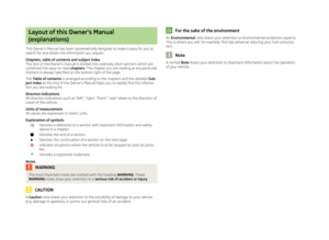 2
2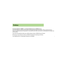 3
3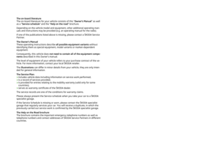 4
4 5
5 6
6 7
7 8
8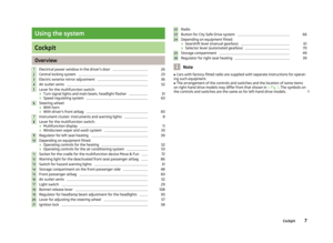 9
9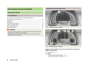 10
10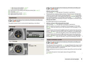 11
11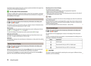 12
12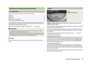 13
13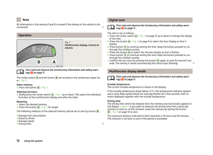 14
14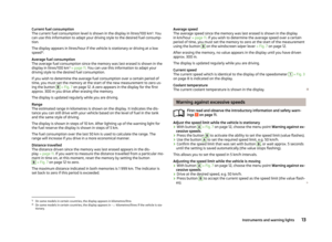 15
15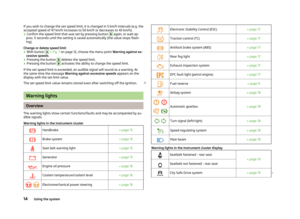 16
16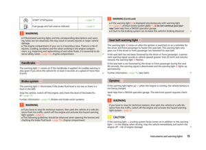 17
17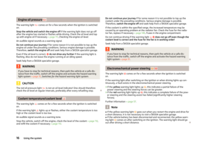 18
18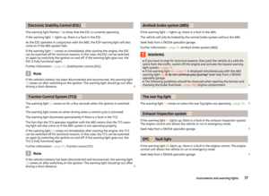 19
19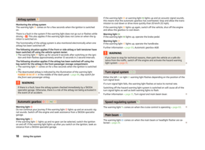 20
20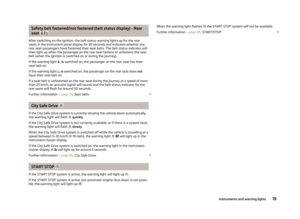 21
21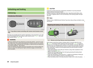 22
22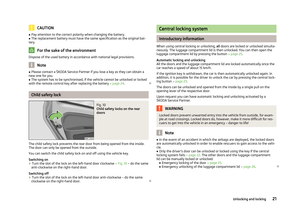 23
23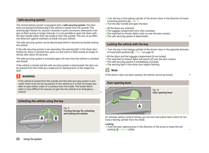 24
24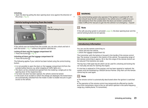 25
25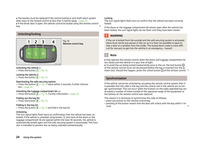 26
26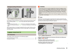 27
27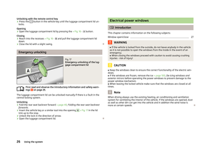 28
28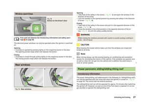 29
29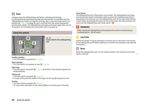 30
30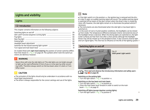 31
31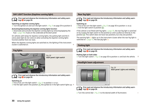 32
32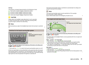 33
33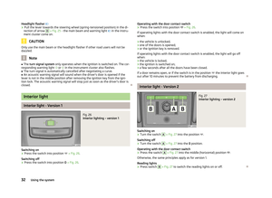 34
34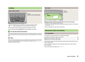 35
35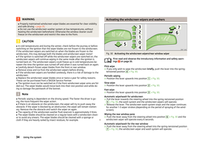 36
36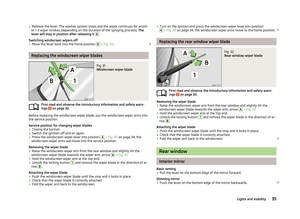 37
37 38
38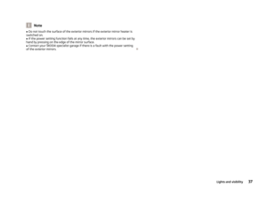 39
39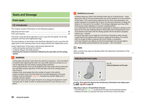 40
40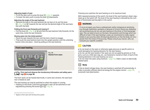 41
41 42
42 43
43 44
44 45
45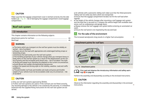 46
46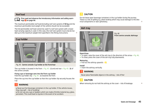 47
47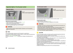 48
48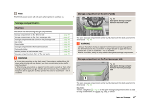 49
49 50
50 51
51 52
52 53
53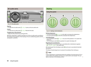 54
54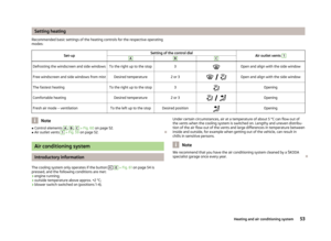 55
55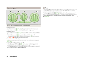 56
56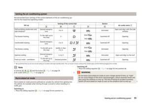 57
57 58
58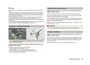 59
59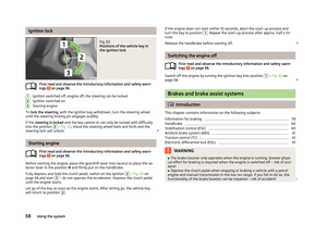 60
60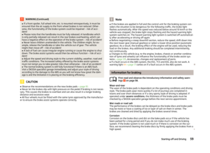 61
61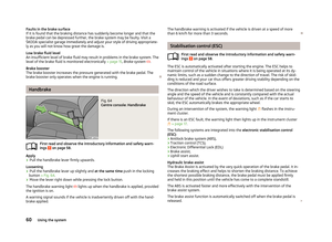 62
62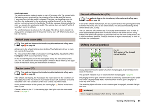 63
63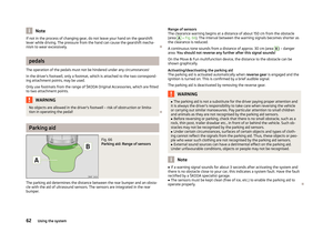 64
64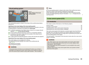 65
65 66
66 67
67 68
68 69
69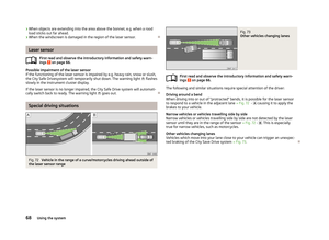 70
70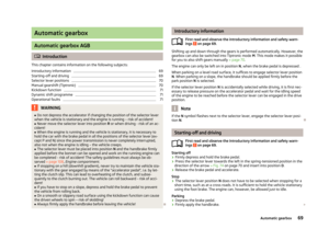 71
71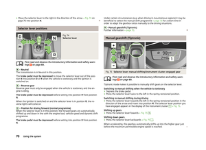 72
72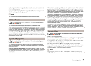 73
73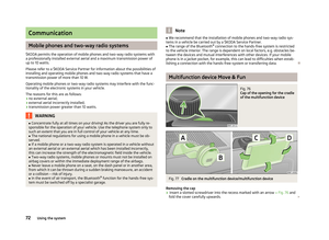 74
74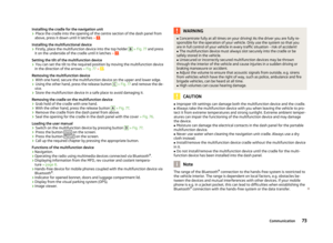 75
75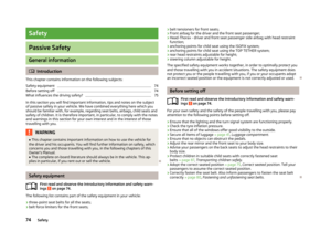 76
76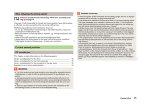 77
77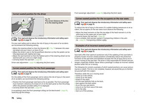 78
78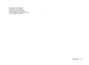 79
79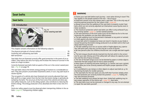 80
80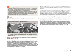 81
81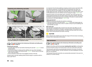 82
82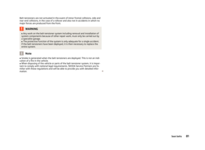 83
83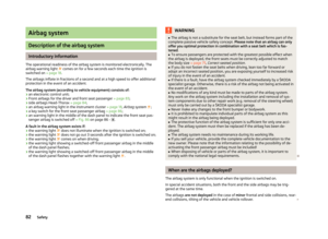 84
84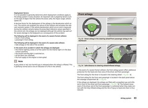 85
85 86
86 87
87 88
88 89
89 90
90 91
91 92
92 93
93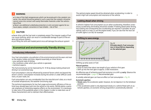 94
94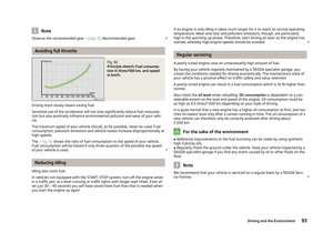 95
95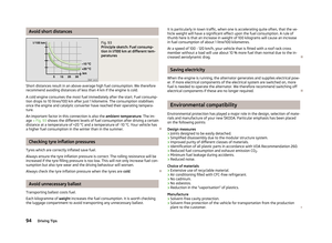 96
96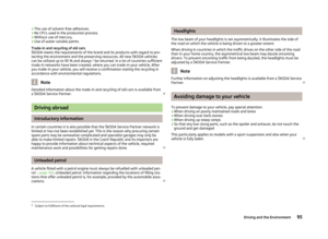 97
97 98
98 99
99 100
100 101
101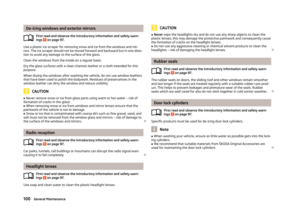 102
102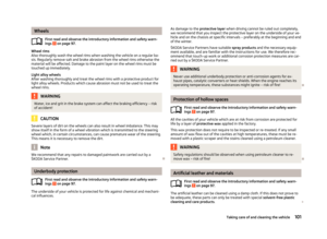 103
103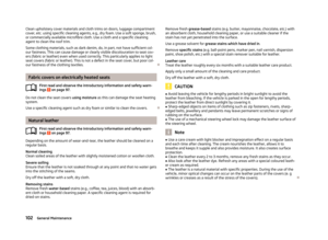 104
104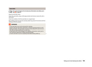 105
105 106
106 107
107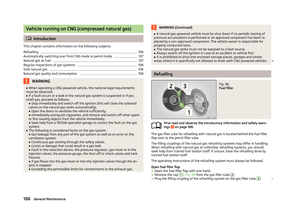 108
108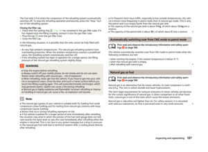 109
109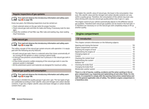 110
110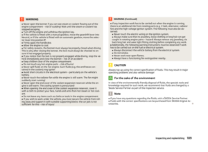 111
111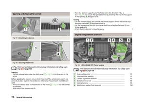 112
112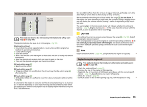 113
113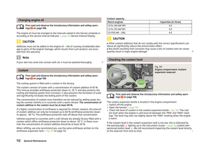 114
114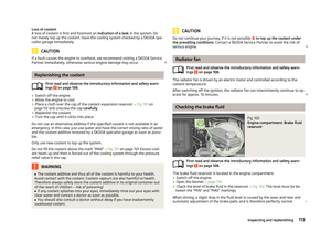 115
115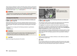 116
116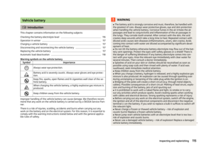 117
117 118
118 119
119 120
120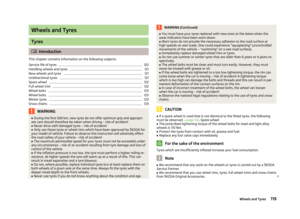 121
121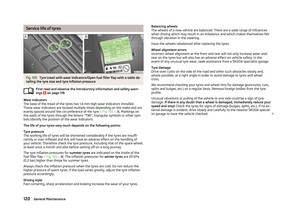 122
122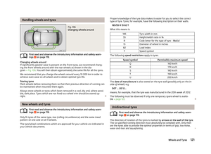 123
123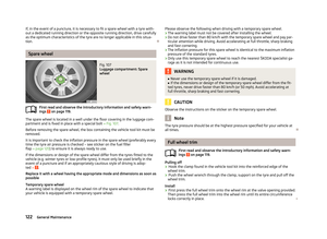 124
124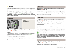 125
125 126
126 127
127 128
128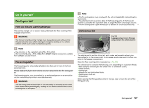 129
129 130
130 131
131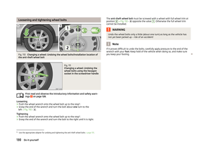 132
132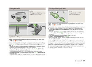 133
133 134
134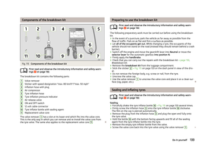 135
135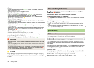 136
136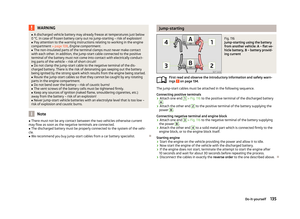 137
137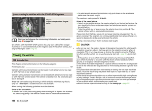 138
138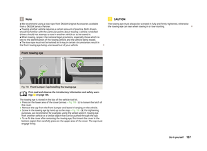 139
139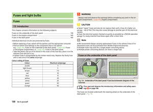 140
140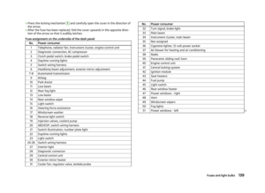 141
141 142
142 143
143 144
144 145
145 146
146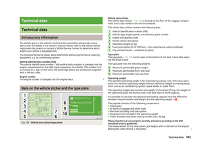 147
147 148
148 149
149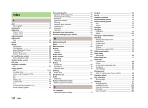 150
150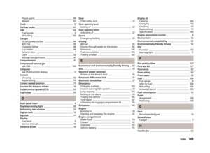 151
151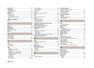 152
152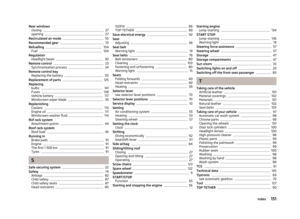 153
153 154
154 155
155 156
156