2012 MERCEDES-BENZ CLS COUPE lock
[x] Cancel search: lockPage 288 of 373
If it is permitted by law to operate communi-
cations equipment whilet
he vehicle is in
motion, you must only do so if the traffic sit-
uationp ermits.Otherwise, yo ucould be dis-
tracted fro mthe traffi cconditions ,cause an
accident and injure yourself and others.
Two-way radios and fa xequipment used with-
out low-reflection exterior aerials can inter-
fere with the vehicle's electronic sand thereby
jeopardise the operatin gsafety of the vehicle
and your safety. Therefore, you must only use
this equipment if it is correctly connected to
as eparate reflection-free exterior aerial. G
WARNING
Excessiv elevels of electromagnetic radiation
may cause damage to your health and the
health of others. Using an exterior aerial takes
int oa ccoun tcurren tscientific discussions
relatin gtothe possible health risk posed by
electromagnetic fields.
Mercedes-Benz recommends the use of an
approved exterior aerial. This ensures:
R optimal mobile phone reception quality in
the vehicle
R mutual influences between the vehicle
electronic sand mobile phones are mini-
mised
An exterior aerial has the following advan-
tages:
R it conducts the electromagnetic fields gen-
erated by awireless device to the exterior.
R the field strengt hinthe vehicle interior is
lower than in avehicle that does not have
an exterior aerial.
i There are various mobile phone brackets
that may be fitted in your vehicle; in some
cases, these are country-specific.
i You can connec taBluetooth ®
-capable
mobile phone with Audio 20, Audio 50 or
COMAND Onlin evia the Bluetooth ®
inter-
face. This also applies if your vehicle is
equipped with convenience telephony. More information on suitable mobile phones,
mobile phone brackets and on connecting
Bluetooth
®
-capable mobile phones with
Audio 20, Audio 50 or COMAND Onlin ecan
be obtained:
R at your Mercedes-Benz Service Centre
R on the Internet at http://www.mercedes-
benz.com/connect
i The function sand services available when
you use the phone depend on your mobile
phone model and servic eprovider.
Using amobile phone If th
emobile phon eisinserted in th emobile
phon ebracket ,you can speak to th eperson
you are callin gusingthe hands-free system.
X Open th etelephone compartment
(Y page 274).
X If required by th edesig noft he mobile
phone bracket, install the sliding adapter
(Y page 286).
X Insert the mobile phone into the mobile
phone bracket (see the separate installa-
tion instructions for the mobile phone fit-
ting).
i On some mobile phone brackets, you first
have to connect the mobile phone via Blue-
tooth ®
to the mobile phone bracket (see
the separate operating instructions for the
mobile phone bracket).
If this is the case, the mobile phone does
not have to be inserted into the bracket for
you to be able to use the telephone func-
tions. However, the charging function and
aerial function are not available.
Operating the mobile phone You can operate the telephone using the
6
and~ buttons on the multifunction
steering wheel. You can operate other mobile
phone functions via the on-board computer
(Y page 217).
When you remove the key from the ignition
lock, the mobile phone stays switched on. Features
285Stowing and features Z
Page 289 of 373
However, yo
ucan no longer use the hands-
free system.
If yo uhaveana ctivecalla nd would like to
take the key ou tofthe ignition lock, first
remove the mobile phone from the bracket.
i Whe nusing abracket connected to the
mobile phone via Bluetooth ®
and yo uwish
to proceed with acall:
Switch to private mode before removing
the key from the ignition lock. Otherwise ,it
may take up to 20 seconds, before the
mobile phone separates from the system.
Only then can the telephone cal lcontinue.
Information on the necessary steps for set-
ting up "private mode "can be found in the
separate mobile phone operating instruc-
tions.
i Not al lmobile phones support "private
mode".
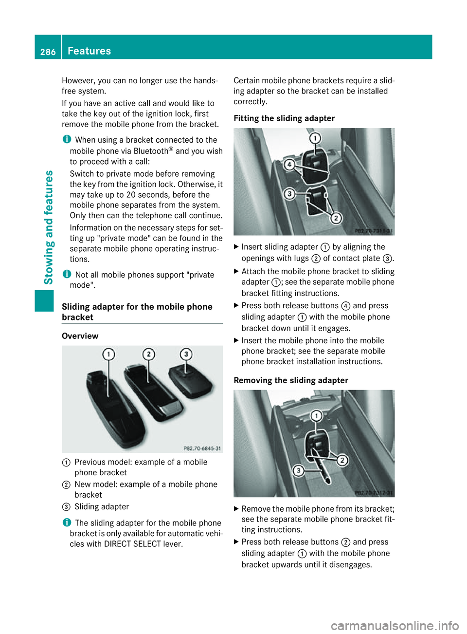
Sliding adapter for the mobile phone
bracket Overview
:
Previou smodel: example of amobile
phone bracket
; New model: example of amobile phone
bracket
= Sliding adapter
i The sliding adapter for the mobile phone
bracket is only available for automati cvehi-
cles with DIRECT SELECT lever. Certain mobile phone brackets require
aslid-
ing adapter so the bracket can be installed
correctly.
Fitting the sliding adapter X
Inser tsliding adapter :by alignin gthe
openings with lugs ;of contac tplate =.
X Attac hthe mobile phon ebracket to sliding
adapter :;see the separat emobile phone
bracket fittin ginstructions.
X Press bot hrelease buttons ?and press
slidin gadapter :with the mobile phone
bracket down until it engages.
X Insert the mobile phon eintot he mobile
phon ebracket ;see the separat emobile
phon ebracket installation instructions.
Removing th eslidin gadapt er X
Remove the mobile phon efromi ts bracket;
se et he separate mobil ephone bracket fit-
ting instructions.
X Press both release buttons ;and press
sliding adapter :with the mobil ephone
bracket upwards unti litdisengages. 286
FeaturesSto
wing an dfeatures
Page 290 of 373
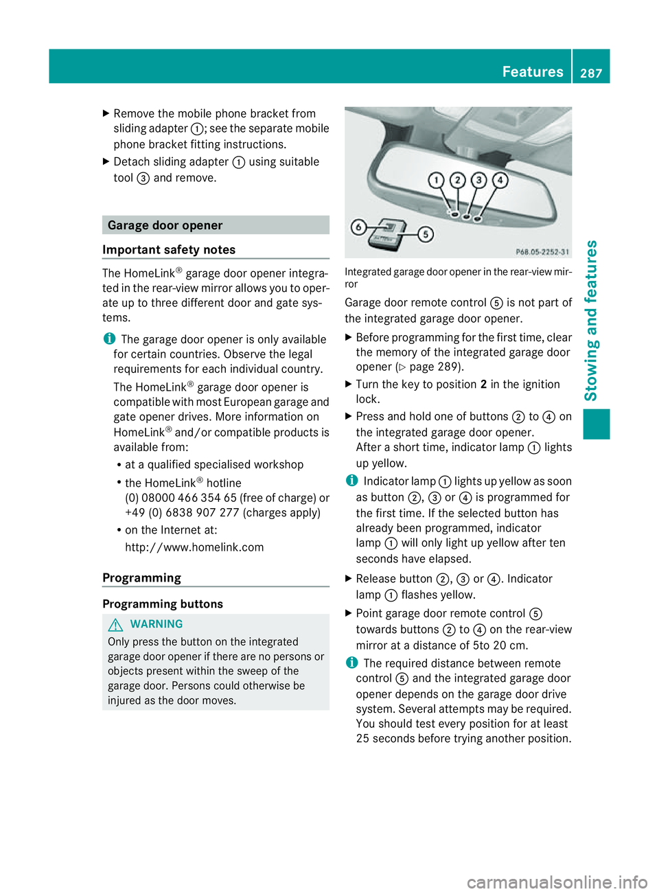
X
Remove th emobile phone bracke tfrom
sliding adapter :;see the separate mobile
phone bracket fitting instructions.
X Detach sliding adapter :using suitable
tool =and remove. Garage door opener
Important safety notes The HomeLink
®
garage door opener integra-
ted in the rear-view mirror allows you to oper-
ate up to three different door and gate sys-
tems.
i The garage door opener is only available
for certain countries. Observe the legal
requirements for each individualc ountry.
The HomeLink ®
garage door opener is
compatible with most European garage and
gate opener drives. More information on
HomeLink ®
and/or compatible products is
available from:
R at aq ualified specialised workshop
R the HomeLink ®
hotline
(0) 08000 466 354 65 (free of charge )or
+49 (0) 6838 907 277 (charges apply)
R on the Internet at:
http://www.homelink.com
Programming Programming buttons
G
WARNING
Only press the button on the integrated
garage door opene rifthere are no persons or
objects present within the sweep of the
garage door. Persons could otherwise be
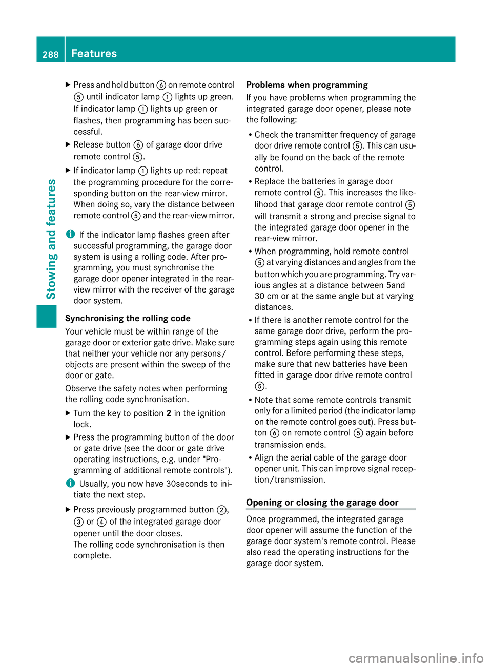
injured as the door moves. Integrated garage door opener in the rear-view mir-
ror
Garage door remote control Ais not part of
the integrated garage door opener.
X Before programming for the first time, clear
the memory of the integrated garage door
opener (Y page 289).
X Turn the key to position 2in the ignition
lock.
X Press and hold one of buttons ;to? on
the integrated garage door opener.
After ashort time, indicator lamp :lights
up yellow.
i Indicator lamp :lights up yellow as soon
as button ;,=or? is programmed for
the first time. If the selected button has
alreadyb een programmed, indicator
lamp :will only light up yellow after ten
seconds have elapsed.
X Release button ;,=or?.I ndicator
lamp :flashes yellow.
X Point garage door remote control A
towards buttons ;to? on the rear-view
mirror at adistance of 5to 20 cm.
i The required distance between remote
control Aand the integrated garage door
opener depends on the garage door drive
system. Several attemptsm ay be required.
You should test every positio nfor at least
25 seconds before trying another position. Features
287Stowing and features Z
Page 291 of 373
X
Press and hold button Bon remot econtrol
A until indicator lamp :lights up green.
If indicator lamp :lights up green or
flashes, then programming has been suc-
cessful.
X Release button Bof garage door drive
remote control A.
X If indicator lamp :lights up red: repeat
the programming procedure for the corre-
sponding button on the rear-view mirror.
When doing so, vary the distance between
remote control Aand the rear-view mirror.
i If the indicator lamp flashes green after
successful programming, the garage door
system is using arolling code. After pro-
gramming, you must synchronise the
garage door opener integrated in the rear-
view mirror with the receiver of the garage
door system.
Synchronising the rolling code
Your vehicle must be within range of the
garage door or exterior gate drive. Make sure
that neither your vehicle nor any persons/
object sare present within the sweep of the
door or gate.
Observe the safety notes when performing
the rolling code synchronisation.
X Turn the key to position 2in the ignition
lock.
X Press the programming button of the door
or gate drive (see the door or gate drive
operating instructions, e.g. under "Pro-
gramming of additional remote controls").
i Usually ,you now have 30seconds to ini-
tiate the next step.
X Press previously programmed button ;,
= or? of the integrated garage door
opener until the door closes.
The rolling code synchronisation is then
complete. Problems when programming
If you have problems when programming the
integrated garage door opener, please note
the following:
R
Check the transmitter frequency of garage
door drive remote control A.This can usu-
ally be found on the back of the remote
control.
R Replace the batteries in garage door
remote control A.This increases the like-
lihood that garage door remote control A
will transmit astronga nd precise signal to
the integrated garage door opener in the
rear-view mirror.
R When programming, hold remote control
A at varying distances and angles from the
button which you are programming. Try var-
ious angles at adistance between 5and
30 cm or at the same angle but at varying
distances.
R If there is another remote control for the
same garage door drive, perform the pro-
gramming steps again using this remote
control. Before performing these steps,
make sure that new batteries have been
fitted in garage door drive remote control
A.
R Note that some remote controls transmit
only for alimited period (the indicator lamp
on the remote control goes out). Press but-
ton Bon remote control Aagain before
transmission ends.
R Align the aerial cable of the garage door
opener unit. This can improve signal recep-
tion/transmission.
Opening or closing the garage door Once programmed, the integrated garage
door opener will assume the function of the
garage door system's remote control. Please
also read the operating instructions for the
garage door system.288
FeaturesStowing and features
Page 292 of 373
X
Turn the key to position 2in the ignition
lock.
X Press button ;,=or? which you have
programmed to operate the garage door.
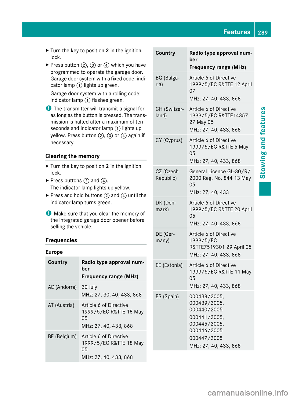
Garage door system with afixed code: indi-
cator lamp :lights up green.
Garage door system with arolling code:
indicator lamp :flashes green.
i The transmitter will transmit asignal for
as long as the button is pressed. The trans-
mission is halted after amaximum of ten
seconds and indicator lamp :lights up
yellow. Press button ;,=or? again if
necessary.
Clearing the memory X
Turn the key to position 2in the ignition
lock.
X Press buttons ;and ?.
The indicator lamp lights up yellow.
X Press and hold buttons ;and ?until the
indicator lamp turns green.
i Make sure that you clear the memory of
the integrated garage door opener before
selling the vehicle.
Frequencies Europe
Country Radio typea
pproval num-
ber
Frequency range (MHz) AD (Andorra) 20 July
MHz: 27, 30, 40, 433, 868
AT (Austria) Article
6ofDirective
1999/5/EC R&TTE 18 May
05
MHz: 27, 40, 433, 868 BE (Belgium) Article
6ofDirective
1999/5/EC R&TTE 18 May
05
MHz: 27, 40, 433, 868 Country Radio typea
pproval num-
ber
Frequency range (MHz) BG (Bulga-
ria) Article
6ofDirective
1999/5/EC R&TTE 12 April
07
MHz: 27, 40, 433, 868 CH (Switzer-
land) Article
6ofDirective
1999/5/EC R&TTE14357
27 May 05
MHz: 27, 40, 433, 868 CY (Cyprus) Article
6ofDirective
1999/5/EC R&TTE 5May
05
MHz: 27, 40, 433, 868 CZ (Czech
Republic) General Licenc
eGL-30/R/
2000 Reg. No. 844 13 May
05
MHz: 27, 40, 433 DK (Den-
mark) Article
6ofDirective
1999/5/EC R&TTE 20 April
05
MHz: 27, 40, 433, 868 DE (Ger-
many) Article
6ofDirective
1999/5/EC
R&TTE751930129A pril 05
MHz: 27, 40, 433, 868 EE (Estonia) Article
6ofDirective
1999/5/EC R&TTE 11 May
05
MHz: 27, 40, 433, 868 ES (Spain) 000438/2005,
000439/2005,
000440/2005
000441/2005,
000445/2005,
000446/2005
000447/2005
MHz: 27, 40, 433, 868 Features
289Stowing and features Z
Page 299 of 373
Useful information
i This Owner's Manual describes all mod-
els, series and optional equipment for your
vehicle that were available at the time of
going to press. National variation sare pos-
sible. Not ethat your vehicle may not be
equipped with all of the function sdescri-
bed. This is also the case for system sand
function srelevan ttosafety.
i Read the information on qualified special-
ist workshops: (Y page 23). Engine compartment
Bonnet
Opening the bonnet G
WARNING
Do not pull the release lever while the vehicle
is in motion. If you do so, the bonnet may open
up and block your view. G
WARNING
There is arisk of injury if the bonnet is open,
even if the engin eisnot running.
Some engin ecomponents can become very
hot.
To avoid the risk of burns, only touc hthose
components described in the Owner's Manual
and observ ethe relevan tsafet ynotes. G
WARNING
The radiator fan between th eradiator and the
engine can start automatically, even if th ekey
has been remove dfromt heignitio nlock. For
this reason, you must not reach into the fan
rotation area. You could otherwise be injured. Vehicles with
apetrol engine: The elec-
tronic ignitio nsystem uses high voltage. For
this reason ,you mus tnever touch ignition
system components( ignition coil, ignition
cables, spark plug connectors or test socket)
while:
R the engine is running
R the engine is being started
R the ignition is switched on and the engine
is being cranked by hand
You could otherwise suffer an electric shock
and be seriously or even fatally injured.
Vehicles with adiesel engine: The elec-
tronic injection control uses high voltage. For
this reason ,you must never touc hinjection
system components while:
R the engin eisrunning
R the engin eisbeing started
R the ignition is switched on
You could otherwise suffer an electric shock
and be seriously or even fatally injured. G
WARNING
The windscreen wipers and wiper linkage
could be set in motion.
When the bonnet is open, you or others could
be injured by the wiper linkage.
Make sure that the windscreen wipers are
switched off. Remove the key or make sure
that no ignition position has been selected
with KEYLESS-GO. All indicator lamps must be
off in the instrumen tpanel.
! Make sure that the windscreen wipers are
not folded away from the windscreen .Oth-
erwise, yo ucould damage the windscreen
wipers or the bonnet. 296
Engine compartmentMaintenance and care
Page 301 of 373
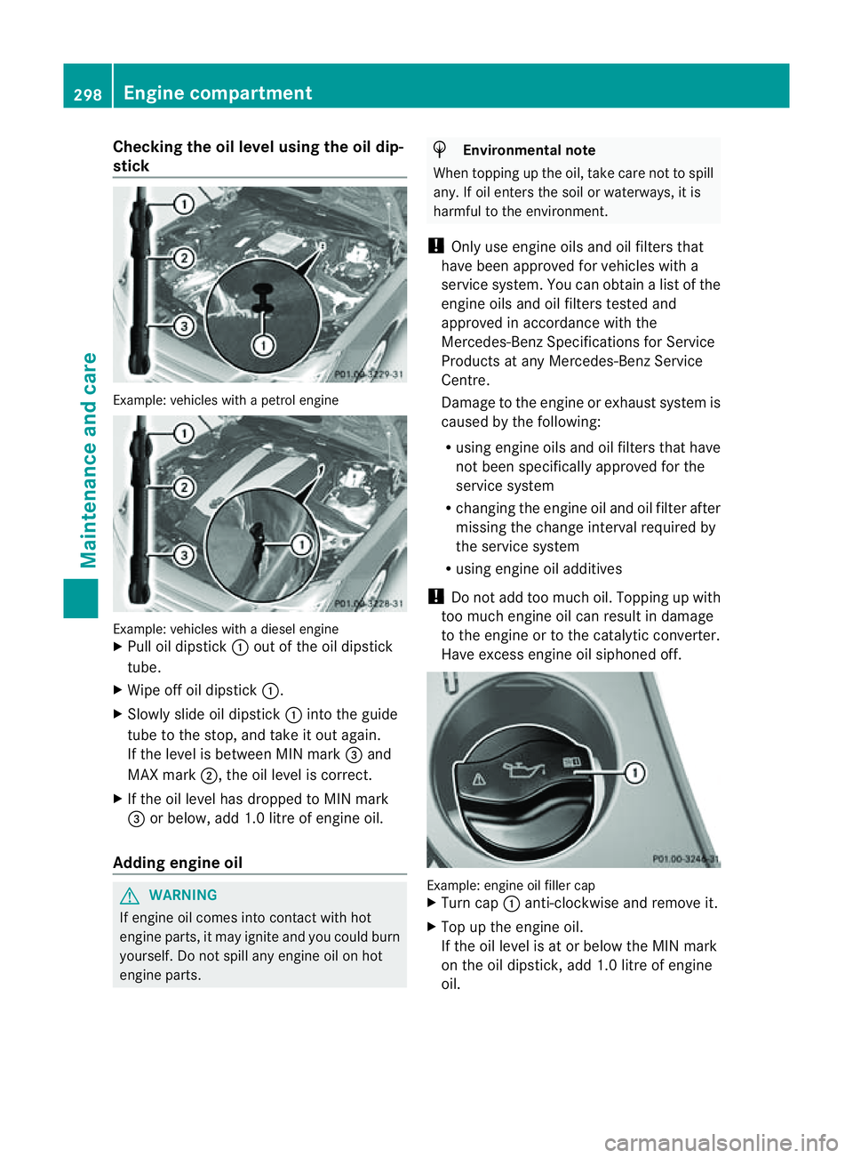
Checking th
eoil level usin gthe oil dip-
stick Example
:vehicles with apetrol engine Example: vehicles with
adiesel engine
X Pull oil dipstick :out of the oil dipstick
tube.
X Wipe off oil dipstick :.
X Slowly slide oil dipstick :into the guide
tube to the stop, and take it out again.
If the level is between MIN mark =and
MAX mark ;,the oil level is correct.
X If the oil level has dropped to MIN mark
= or below, add 1.0 litre of engine oil.
Adding engine oil G
WARNING
If engine oil comes into contact with hot
engine parts, it may ignite and you could burn
yourself. Do not spill any engine oil on hot
engine parts. H
Environmental note
When topping up the oil, take care not to spill
any. If oil enters the soil or waterways, it is
harmful to the environment.
! Only use engine oils and oil filters that
have been approved for vehicles with a
service system. You can obtain alist of the
engine oils and oil filters tested and
approved in accordance with the
Mercedes-Benz Specification sfor Service
Product satany Mercedes-Benz Service
Centre.
Damage to the engine or exhaust system is
caused by the following:
R using engine oils and oil filters that have
not been specifically approved for the
service system
R changin gthe engine oil and oil filter after
missing the change interval required by
the service system
R using engine oil additives
! Do not add too much oil. Topping up with
too much engine oil can result in damage
to the engine or to the catalytic converter.
Have exces sengine oil siphoned off. Example: engine oil filler cap
X
Turn cap :anti-clockwise and remove it.
X Top up the engine oil.
If the oil level is at or below the MIN mark
on the oil dipstick ,add 1.0 litre of engine
oil. 298
Engine compartmentMaintenance and care
Page 302 of 373
X
Replac ecap : on th efiller neck and turn
clockwise.
Mak esuret hatthe cap locks securel yinto
place.
X Chec kthe oil level again with the oil dip-
stick (Y page 298).
For further information on engine oil, see
(Y page 363). Other service products
Checking the coolant level G
WARNING
The cooling system is pressurised. Therefore,
only unscrew the cap once the engine has
cooled down. The coolant temperature gauge
must display less than 70 †.Otherwise, you
could be scalded if hot coolant escapes. X
Park the vehicl eonalevel surface.
Onl ycheck the coolant level if the vehicle
is on alevel surface and the engine has
coole ddown.
X Turn the key to position 2in the ignition
lock (Y page 141).
On vehicles with KEYLESS-GO, press the
Start/Stop button twice (Y page 141).
X Check the coolant temperatur edisplay in
the instrument cluster.
Th ec oolant temperatur emustbeb elow
70 †.
X Turn the key to position 0(Y page 141) in
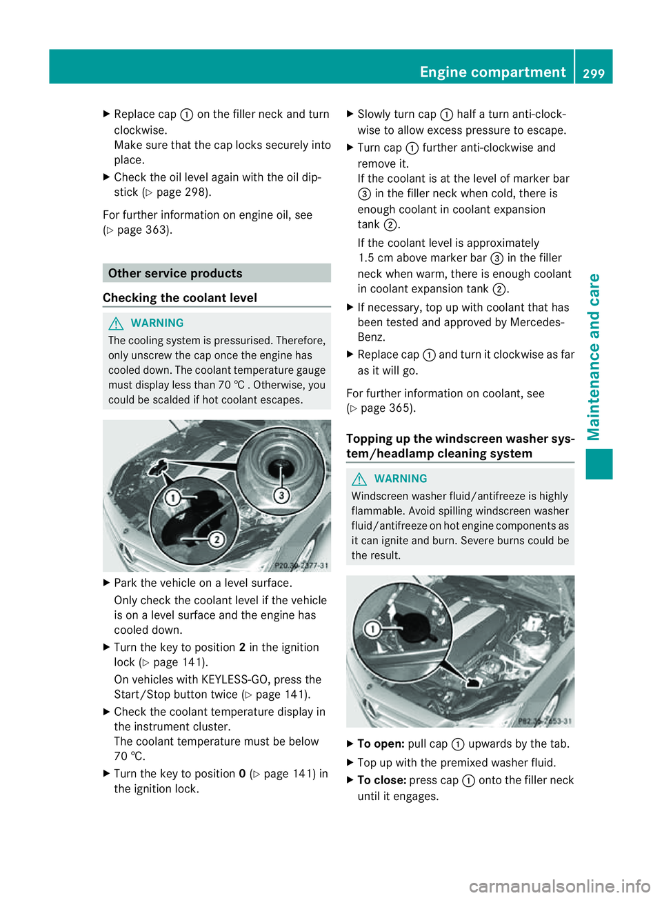
the ignition lock. X
Slowl yturnc ap : half aturna nti-clock-
wise to allow exces spressure to escape.
X Turn cap :further anti-clockwis eand
remove it.
If th ecoolan tisatt heleve lofm arkerbar
= in th efille rneck when cold, ther eis
enough coolant in coolant expansion
tank ;.
If the coolant level is approximately
1.5 cm above marker bar =in the filler
neckw hen warm, there is enough coolant
in coolant expansion tank ;.
X If necessary, top up with coolant that has
been tested and approved by Mercedes-
Benz.
X Replace cap :and turn it clockwise as far
as it will go.
For further information on coolant, see
(Y page 365).
Topping up the windscreen washer sys-
tem/headlam pcleaning system G
WARNING
Windscreen washer fluid/antifreez eishighly
flammable. Avoid spilling windscreen washer
fluid/antifreez eonhot engin ecomponent sas
it can ignit eand burn. Severe burns could be
the result. X
To open: pull cap:upwards by the tab.
X Top up with the premixed washer fluid.
X To close: press cap :ontothe filler neck
until it engages. Engine compartment
299Maintenance and care Z