2012 MERCEDES-BENZ CLS COUPE lock
[x] Cancel search: lockPage 341 of 373
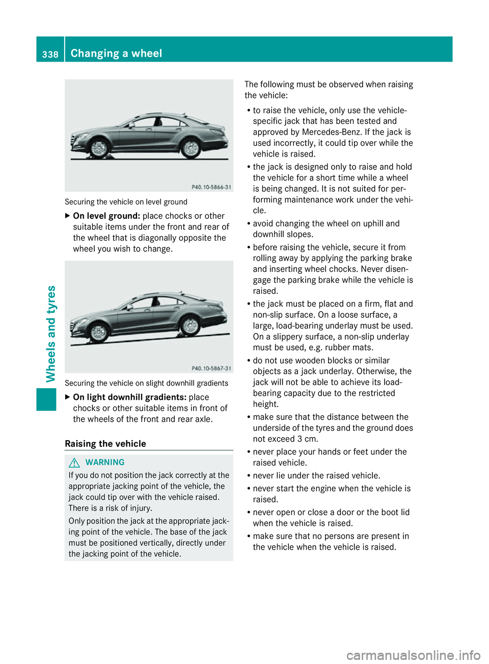
Securing the vehicle on level ground
X
On level ground: place chocks or other
suitabl eitem sunder the front and rea rof
the whee ltha tisd iagonally opposite the
wheel you wish to change. Securing the vehicle on slight downhill gradients
X
On light downhill gradients: place
chocks or other suitablei tems in front of
the wheels of the front and rear axle.
Raising the vehicle G
WARNING
If you do not position the jack correctly at the
appropriate jacking point of the vehicle, the
jack could tip over with the vehicle raised.
There is arisk of injury.
Only position the jack at the appropriate jack-
ing point of the vehicle. The base of the jack
must be positioned vertically, directly under
the jacking point of the vehicle. The following must be observed when raising
the vehicle:
R
to raise the vehicle, only use the vehicle-
specific jack that has been tested and
approved by Mercedes-Benz.Ift he jack is
used incorrectly, it could tip over while the
vehicle is raised.
R the jack is designed only to raise and hold
the vehicle for ashort time while awheel
is being changed. It is not suited for per-
forming maintenance work under the vehi-
cle.
R avoid changing the wheel on uphilla nd
downhill slopes.
R before raising the vehicle, secure it from
rolling awaybya pplying the parking brake
and inserting wheel chocks. Never disen-
gage the parking brake while the vehicle is
raised.
R the jack must be placed on afirm, flat and
non-slip surface. On aloose surface, a
large, load-bearing underlay must be used.
On aslippery surface, anon-slip underlay
must be used, e.g. rubber mats.
R do not use wooden blocks or similar
objects as ajack underlay.O therwise, the
jack will no tbea ble to achiev eits load-
bearin gcapacity due to the restricted
height.
R mak esure that the distanc ebetween the
underside of the tyre sand the groun ddoes
not exceed 3cm.
R never place your hands or feet under the
raised vehicle.
R never lie under the raised vehicle.
R never start the engine when the vehicle is
raised.
R never open or clos eadoor or the boot lid
when the vehicle is raised.
R mak esure that no persons are present in
the vehicle when the vehicle is raised. 338
Changin
gawheelWheels and tyres
Page 342 of 373
X
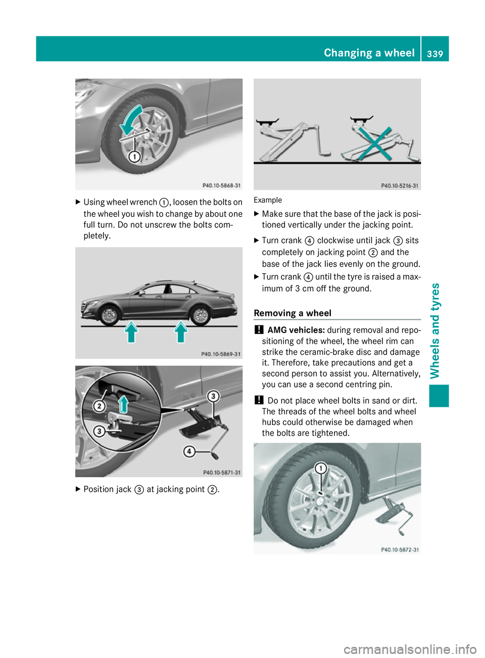
Using wheel wrench :,loosen the bolts on
the wheel you wish to change by abouto ne
full turn. Do not unscrew the bolts com-
pletely. X
Positio njack =at jackin gpoint ;. Example
X
Mak esure that th ebase of th ejackisp osi-
tioned vertically under the jacking point.
X Turn crank ?clockwise until jack =sits
completely on jacking point ;and the
base of the jack lies evenly on the ground.
X Turn crank ?until the tyre is raised amax-
imum of 3cmoff the ground.
Removing awheel !
AMG vehicles: during removaland repo-
sitioning of the wheel, the wheel rim can
strike the ceramic-brake disc and damage
it. Therefore, take precautions and get a
second perso ntoassist you. Alternatively,
you can use asecond centring pin.
! Do not place wheel bolts in sand or dirt.
The threads of the wheel bolts and wheel
hubs could otherwise be damaged when
the bolts are tightened. Changing
awheel
339Wheels and tyres Z
Page 344 of 373
Tightenin
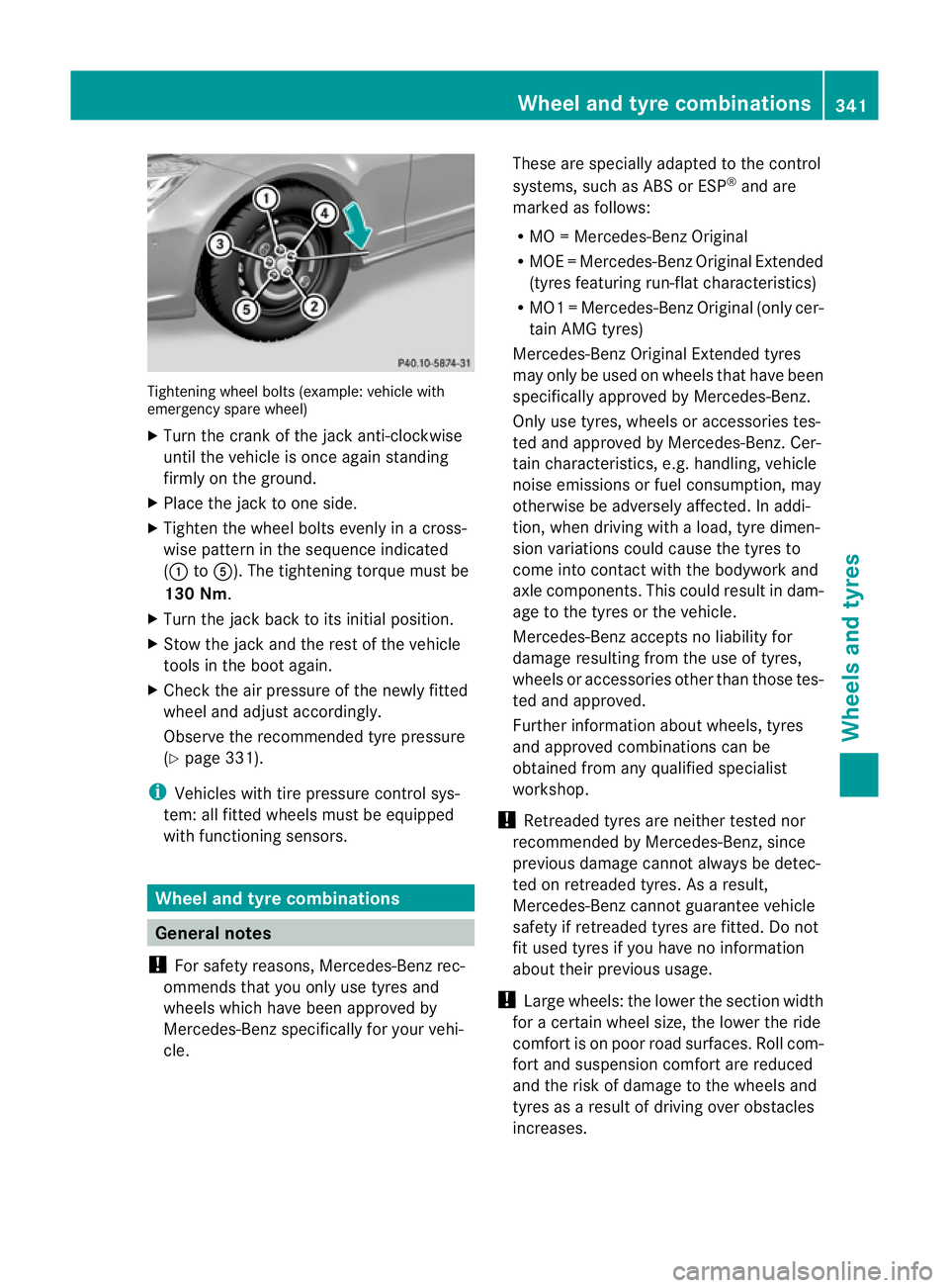
gwheel bolts (example: vehicle with
emergenc yspare wheel)
X Turn the crank of the jack anti-clockwise
until the vehicle is once again standing
firmly on the ground.
X Place the jack to one side.
X Tighten the wheel bolts evenly in across-
wise pattern in the sequence indicated
(: toA). The tightening torque must be
130 Nm.
X Turn the jack back to its initial position.
X Stow the jack and the rest of the vehicle
tools in the boot again.
X Check the air pressure of the newly fitted
wheel and adjust accordingly.
Observe the recommended tyre pressure
(Y page 331).
i Vehicles with tire pressure control sys-
tem: all fitted wheels must be equipped
with functioning sensors. Wheel and tyrec
ombinations General notes
! For safety reasons, Mercedes-Benz rec-
ommends that you only use tyres and
wheels which have been approved by
Mercedes-Benz specifically for your vehi-
cle. These are specially adapted to the control
systems, such as ABS or ESP
®
and are
marked as follows:
R MO =Mercedes-BenzO riginal
R MOE =Mercedes-Benz Original Extended
(tyres featuring run-flat characteristics)
R MO1 =Mercedes-BenzO riginal (only cer-
tain AMG tyres)
Mercedes-Benz Original Extended tyres
may only be usedonw heels that have been
specifically approved by Mercedes-Benz.
Only use tyres, wheels or accessories tes-
ted and approved by Mercedes-Benz. Cer-
tain characteristics, e.g. handling, vehicle
noise emissions or fuel consumption, may
otherwise be adversely affected. In addi-
tion, when driving with aload, tyre dimen-
sion variations could cause the tyres to
come into contact with the bodywork and
axle components.T his could result in dam-
age to the tyres or the vehicle.
Mercedes-Ben zaccepts no liability for
damag eresulting from the us eoftyres,
wheel soraccessorie sothe rthan those tes-
ted and approved.
Further information about wheels, tyres
and approved combinations can be
obtained from any qualified specialist
workshop.
! Retreaded tyres are neither tested nor
recommended by Mercedes-Benz, since
previous damage cannot always be detec-
ted on retreaded tyres. As aresult,
Mercedes-Ben zcannot guarante evehicle
safety if retreade dtyres are fitted. Do not
fit used tyres if you have no information
about their previous usage.
! Large wheels :the lower the section width
for acertain wheel size, the lower the ride
comfort is on poor road surfaces. Roll com-
fort and suspension comfort are reduced
and the risk of damage to the wheels and
tyres as aresult of driving over obstacles
increases. Wheel and tyrec
ombinations
341Wheels and tyres Z
Page 354 of 373
Emergency spare wheel
Important safety notes
G
WARNING
The wheel/tyr edimension sand th etyret ype
of th espar ew heel/emergency spar ewheel
and th ewheel to be replaced may differ. Fit-
tin gas parew heel/emergency spar ewheel
may severel yimpair th edriving characteris-
tics. Ther eisarisk of accident.
To prevent hazardous situations:
R Adap tyour driving style accordingly and
drive carefully.
R Never fit more than one spare wheel/emer-
gency spare wheel if the dimesions are dif-
ferent to those of the wheel being replaced.
R Only use aspare wheel/emergency spare
wheel briefly if the dimesions are different
to those of the wheel being replaced.
R Do not switch off ESP ®
.
R Have the spare wheel/emergency spare
wheel in question replaced at the nearest
qualified specialist workshop. Make sure
that the wheel/tyre dimensions and tyre
type are correct.
When using an emergenc yspare wheel or
spare wheel of adifferent size, you must not
exceed the maximum speed of 80 km/h.
Snow chains must not be fitted to emergency
spare wheels. General notes
You should regularly check the pressure of all
your tyres, including the emergenc yspare
wheel, particularly prior to long trips, and cor-
rect the pressure as necessary (Y page 331).
The applicabl evalue is found on the wheel or
under "Technical data" (Y page 354).
An emergenc yspare wheel may also be fitted
against the direction of rotation .Observe the
time restriction on use as well as the speed
limitation specified on the emergency spare
wheel. Replace the tyres after six years at the latest,
regardless of wear. This also applies to the
emergency spare wheel.
i
When you are drivin gwith the collapsible
emergency spare wheel fitted, the tyre
pressure loss warning system or the tyre
pressure monitor cannot function reliably.
Only restart the tyre pressure loss warning
system/tyre pressure monitor when the
defective wheel has been replaced with a
new wheel.
Vehicles with tyr epressure monitor:
after mounting an emergency spare wheel,
the system may still display the tyre pres-
sure of the removed wheel for afew
minutes. The value displayed for the moun-
ted emergency spare wheel is not the same
as the curren ttyre pressure of the emer-
genc yspare wheel. Removing the "Minispare" emer-
gency spar
ewheel/collapsible emer-
gency spar ewheel
Removing the "Minispare" emergency
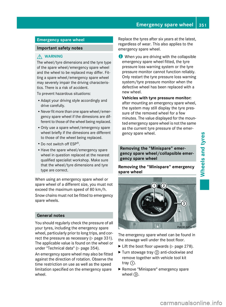
spar ewheel The emergency spare wheel can be found in
the stowage well under the boot floor.
X Lift the boot floor upwards (Y page 278).
X Turn stowage tray ;anti-clockwise and
remov etogether with vehicle tool kit
tray :.
X Remove "Minispare" emergency spare
wheel =. Emergency spare wheel
351Wheels and tyres Z
Page 356 of 373
X
Insert connector ?into the cigarette
lighter socket or into a12Vsocket in your
vehicle.
Observe the notes on the cigarette lighter
(Y page 283). Observe the notes on sock-
ets (Y page 283).
X Turn the key to position 1in the ignition
lock (Y page 141).
X Press on/off switch Aon the tyre inflation
compressor to I.
The tyre inflation compressor is switched
on. The tyre is inflated. The tyre pressure is
shown on pressure gauge =.
X Pump the tyre to the specified tyre pres-
sure.
The specified tyre pressure is printed on
the yellow label of the emergency spare
wheel.
X When the specified tyre pressure has been
reached, press on/off switch Aon the
electric air pump to 0.
The tyre inflation compressor is switched
off.
X Turn the key to position 0in the ignition
lock.
X If the tyre pressure is higher than the speci-
fied pressure, press pressure release but-
ton ;until the correct tyre pressure has
been reached.
X Unscrew union nut :on the air hose from
the valve.
X Screw the valve cap onto the collapsible
emergency spare wheel valve again.
X Stow plug ?and the air hose in the lower
section of the blower housing.
X Stow the tyre inflation compressor in the
vehicle. Emergency sparew
heel
353Wheels and tyres Z
Page 369 of 373
The coolant is checked at every maintenance
interval at aqualified specialist workshop.
i When the vehicle is first delivered, it is fil-
led with acoolant mixture that ensures
adequate antifreeze and corrosion protec-
tion. Windscreen and headlam
pcleaning
system
Important safet ynotes G
WARNING
Windscreen washer fluid/antifreez eishighly
flammable. Avoid spilling windscreen washer
fluid/antifreez eonhot engin ecomponent sas
it can ignit eand burn. Severe burns could be
the result.
! Only use washer fluid that is suitable for
plastic lamp lenses, e.g. MB SummerFit or
MB WinterFit. Unsuitable washer fluid
could damage the plastic lense softhe
headlamps.
! Do not use distilled or de-ionised water in
the washer fluid reservoir. Otherwise, the
level sensor may be damaged.
! Only the washer fluids SummerFit and
WinterFit can be mixed. Otherwise, the
spraying nozzles could become blocked.
At temperatures above freezing:
X Fill the washer fluid reservoir with amixture
of water and washer fluid, e.g. MB Sum-
merFit.
Mix 1part MB SummerFit to 100 parts water. At temperatures below freezing:
X
Fill the washer fluid reservoir with amixture
of water and washer fluid, e.g. MB Winter-
Fit.
Adapt the mixing ratio to the outside temper-
ature.
R Down to Ò10 †: mix 1part MB WinterFit
with 2partsw ater.
R Down to Ò20 †: mix 1part MB WinterFit
wit h1p art water.
R Down to Ò29 †: mix 2partsMBW interFit
wit h1p art water.
i Addw ashe rfluid concentrate, e.g. MB
SummerFit or MB WinterFit, to the washer
fluid all year round. Vehicle data
General notes
Please not ethat for the specified vehicle
data:
R the height sspecified may vary as aresult
of:
- tyres
- load
- conditio nofthe suspension
- optional equipment
R items of optional equipment increase the
unladen weight and reduce the maximum
payload. The unladen weight is specified in
accordance with EC directive and includes:
- driver (68 kg)
- luggage (7 kg)
- all fluids (fuel tank 90% full)
R vehicle-specific weight information can be
found on the vehicle identification plate
(Y page 359).
R only for certain countries: you can find vehi-
cle-specific vehicle data in the COC docu-
ments( CERTIFICATE OF CONFORMITY).
These documents are delivered with your
vehicle. 366
Vehicle dataTechnical data