2012 MERCEDES-BENZ CLS COUPE length
[x] Cancel search: lengthPage 103 of 373
!
Make sure that the rear window roller
sunblind is retracted when removing the
rear head restraints. Otherwise, you could
damage the roller sunblind. X
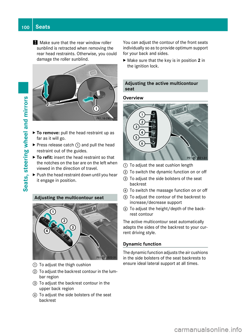
To remove: pull the head restraint up as
far as it will go.
X Press release catch :and pull the head
restraint out of the guides.
X To refit: insert the head restraint so that
the notches on the bar are on the left when
viewed in the direction of travel.
X Push the head restraint down until you hear
it engage in position. Adjusting the multicontour seat
:
To adjust the thigh cushion
; To adjust the backrest contour in the lum-
bar region
= To adjust the backrest contour in the
upper back region
? To adjust the side bolsters of the seat
backrest You can adjust the contour of the front seats
individually so as to provide optimum support
for your back and sides.
X Make sure that the key is in position 2in
the ignition lock. Adjusting the active multicontour
seat
Overview :
To adjust the seat cushion length
; To switch the dynamic function on or off
= To adjust the side bolsters of the seat
backrest
? To switch the massage function on or off
A To adjust the contour of the backrest to
increase/decrease support
B To adjust the height/depth of the back-
rest contour
The active multicontour seat automatically
adapts the sides of the backrest to your cur-
rent driving style.
Dynamic function The dynamic function adjusts the air cushions
in the side bolsters of the seat backrests to
ensure ideall
ateral support at all times.100
SeatsSeats, steering wheela
nd mirrors
Page 110 of 373
X
Make sure that the vehicle is stationary and
that the key is in position 2in the ignition
lock.
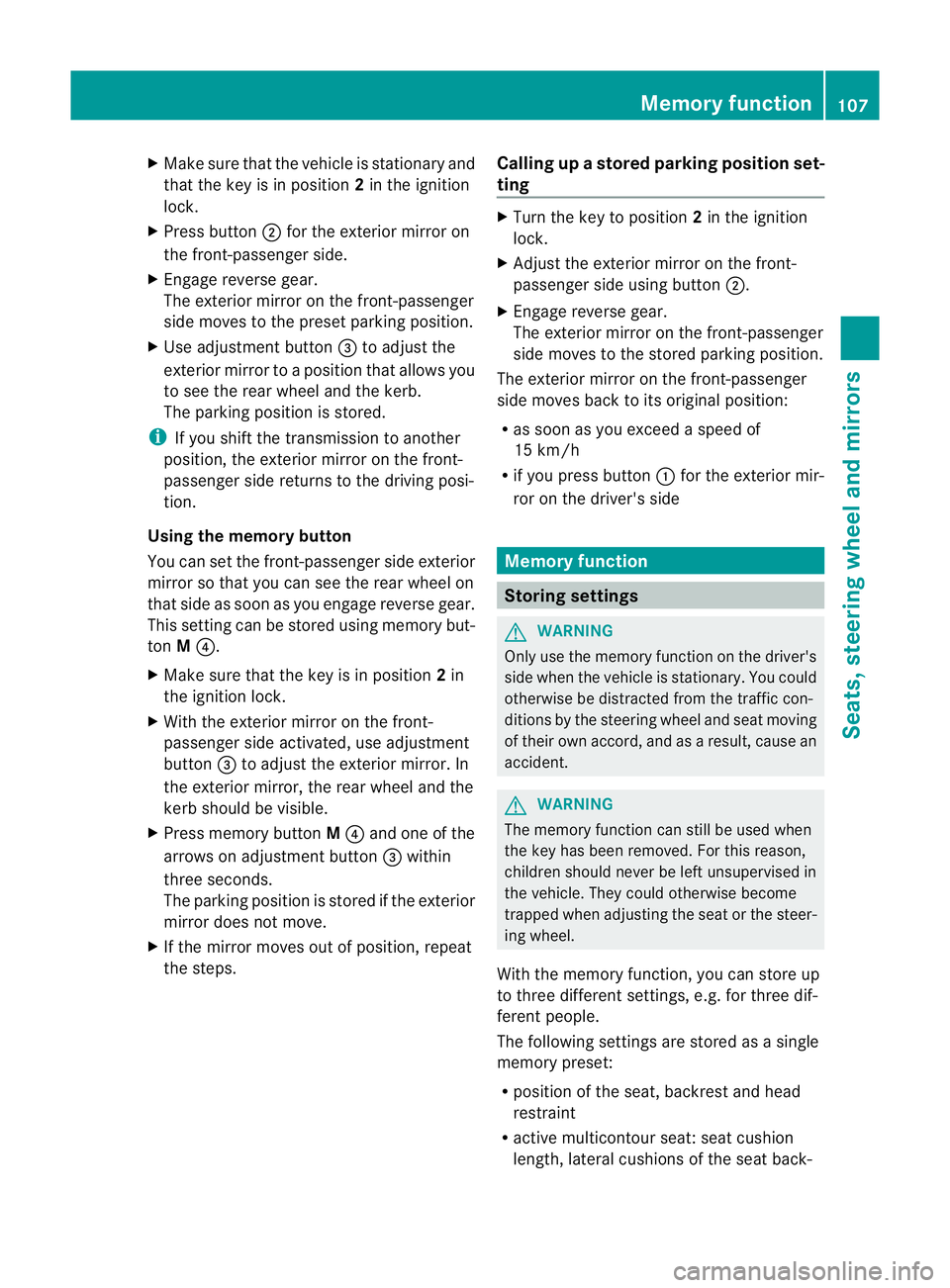
X Press button ;for the exterior mirror on
the front-passenger side.
X Engage reverse gear.
The exterior mirror on the front-passenger
side moves to the preset parking position.
X Use adjustment button =to adjust the
exterior mirror to aposition that allowsy ou
to see the rear wheel and the kerb.
The parking position is stored.
i If you shift the transmission to another
position, the exterior mirror on the front-
passenger side returns to the driving posi-
tion.
Using the memory button
You can set the front-passenger side exterior
mirror so that you can see the rear wheel on
that side as soon as you engage reverse gear.
This settingc an be stored using memory but-
ton M?.
X Make sure that the key is in position 2in
the ignition lock.
X With the exterior mirror on the front-
passenger side activated, use adjustment
button =to adjust the exterior mirror. In
the exterior mirror, the rear wheel and the
kerb should be visible.
X Press memory button M? and one of the
arrows on adjustment button =within
three seconds.
The parking position is stored if the exterior
mirror does not move.
X If the mirror moves out of position, repeat
the steps. Calling up
astore dparking position set-
ting X
Tur nthe key to position 2in the ignition
lock.
X Adjust the exterior mirror on the front-
passenger side using button ;.
X Engage reverse gear.
The exterior mirror on the front-passenger
side moves to the stored parking position.
The exterior mirror on the front-passenger
side moves back to its original position:
R as soon as you exceed aspeed of
15 km/h
R if you press button :for the exterior mir-
ror on the driver's side Memory function
Storing settings
G
WARNING
Only use the memory function on the driver's
side when the vehicle is stationary. You could
otherwise be distracted from the traffic con-
ditions by the steering wheel and seat moving
of their own accord, and as aresult, cause an
accident. G
WARNING
The memory function can still be used when
the key has been removed. For this reason,
children should never be left unsupervised in
the vehicle. They could otherwise become
trapped when adjusting the seat or the steer-
ing wheel.
With the memory function, you can store up
to three different settings, e.g. for three dif-
ferent people.
The following settings are stored as asingle
memory preset:
R position of the seat, backrest and head
restraint
R active multicontour seat: seat cushion
length, lateral cushions of the seat back- Memory function
107Seats, steering wheela nd mirrors Z
Page 120 of 373
The system automatically adapts the dipped-
beam headlamp range depending on the dis-
tancetot he other vehicle. Oncet he system
no longer detect sany other vehicles, it reac-
tivates the main-beam headlamps.
The system's optical sensor is located behind
the windscreen near the overhead control
panel.
Switching Adaptive Highbeam Assist
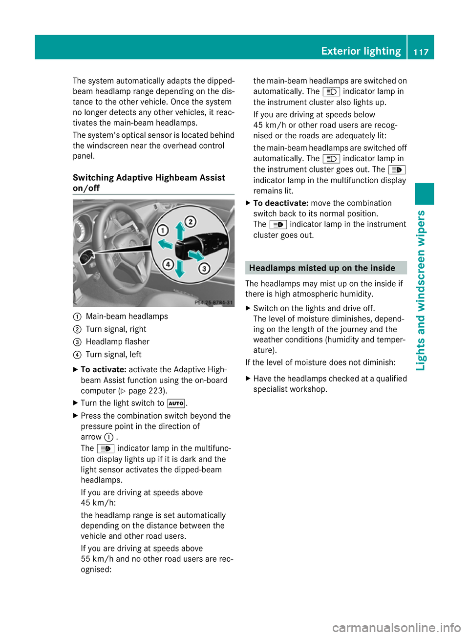
on/off :
Main-beam headlamps
; Turn signal, right
= Headlamp flasher
? Turn signal, left
X To activate: activatethe Adaptive High-
beam Assist function using the on-board
computer (Y page 223).
X Turn the light switch to Ã.
X Press the combination switch beyond the
pressure point in the direction of
arrow :.
The _ indicator lamp in the multifunc-
tion display lights up if it is dark and the
light sensor activates the dipped-beam
headlamps.
If you are driving at speeds above
45 km/h:
the headlamp range is set automatically
depending on the distanc ebetween the
vehicle and other road users.
If you are driving at speeds above
55 km/ha nd no other road users are rec-
ognised: the main-beam headlamps are switched on
automatically. The
Kindicator lamp in
the instrument cluster also lights up.
If you are driving at speeds below
45 km/ho rother road users are recog-
nised or the roads are adequately lit:
the main-beam headlamps are switched off
automatically. The Kindicator lamp in
the instrument cluster goes out. The _
indicator lamp in the multifunction display
remains lit.
X To deactivate: move the combination
switch back to its normal position.
The _ indicator lamp in the instrument
cluster goes out. Headlamps misted up on the inside
The headlamps may mist up on the inside if
there is high atmospheric humidity.
X Switc hont he lights and drive off.
The level of moisture diminishes, depend-
ing on the length of the journey and the
weather conditions (humidity and temper-
ature).
If the level of moisture does not diminish:
X Have the headlamps checked at aqualified
specialist workshop. Exterior lighting
117Lights and windscreen wipers Z
Page 143 of 373
Useful information
i This Owner's Manual describes all mod-
els, series and optional equipment for your
vehicle that were available at the time of
going to press. National variation sare pos-
sible. Not ethat your vehicle may not be
equipped with all of the function sdescri-
bed. This is also the case for system sand
function srelevan ttosafety.
i Read the information on qualified special-
ist workshops: (Y page 23). Running-in notes
Important safet
ynotes
New and replaced brake pads and discs only
reach their optimum brakin geffec tafter sev-
eral hundre dkilometres of driving. Compen-
sate for this by applying greater force to the
brake pedal. The first 1,500 km
If you treat the engine with sufficient care
from the very start, you wil lberewarded with
excellent performance for the remainder of
the engine' slife.
R Drive at varying vehicle speeds and engine
speeds for the first 1,500 km.
R Avoid overstraining the vehicle during this
period, e.g. driving at ful lthrottle.
R Change gea ringood time, before the rev
counter needle is Ôof the way to the red
area of the rev counter.
R Do not shift down agear manually in order
to brake.
R Try to avoid depressing the accelerator
pedal beyond the point of resistanc e(kick-
down).
R The shift ranges 3,2or 1should only be
engaged when driving slowly, e.g. when
driving in mountainous terrain. After 1500 km
,you may graduall yaccelerate
the vehicle to full road and engine speeds.
Additional running-in notes for AMG vehicles:
R Do not drive at speeds above 140 km/hf or
the first 1500 km.
R Only allow the engine to reach amaximum
engine speed of 4500 rpm briefly.
i You should also observe these notes on
runnin ginift he engine or parts of the drive
train on your vehicle have been replaced. AMG vehicles with rear axle differen-
tial lock
Your vehicle is equipped with aself-locking
differential on the rear axle. Change the oil
after arunning-in period of 3000kmto
improve protection of the rear axle differen-
tial. This oil change will lengthen the service
life of the differential. Have the oil change
carried out at aqualified specialist workshop. Driving
Important safet
ynotes G
WARNING
Objects in the driver's footwell can restrict the
pedal travel or obstruct adepressed pedal.
The operatin gand road safety of the vehicle
is jeopardised. There is arisk of an accident.
Make sure that all objects in the vehicle are
stowed correctly, and that they cannot enter
the driver's footwell. Fit the floormats
securely and as specified in order to ensure
sufficien tclearanc efor the pedals. Do not use
loose floormats. G
WARNING
Unsuitable footwear can hinde rcorrect usage
of the pedals, e.g.:
R shoes with thick soles
R shoes with high heels
R slippers 140
DrivingDriving and parking
Page 195 of 373
G
WARNING
Please note that objects not at ground level
may appear to be further awayt han they
actually are. These include:
R the bumper of avehicl ethat is parked
behind yourv ehicle
R at railer drawbar
R the ball coupling of atrailer tow hitch
R the tail-en dofalorry
R slanted posts
The lines are only guides, not accurat emeas-
urement softhe distanc etoanobstacle.
Therefore, you should never pass the red line
when approaching an obstacle. You could oth-
erwise cause an acciden tand injure yourself
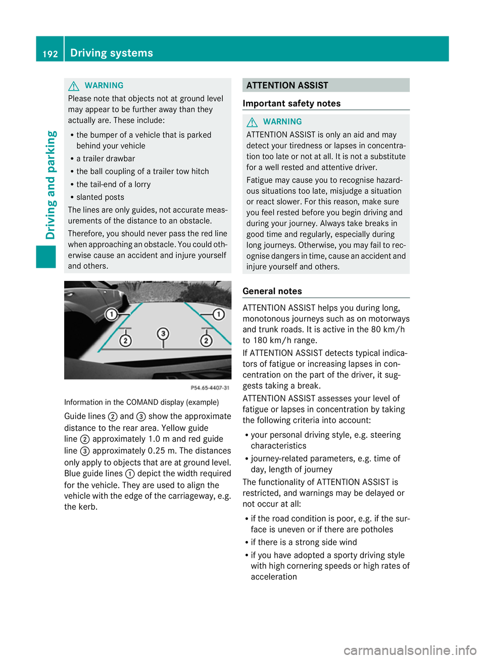
and others. Information in the COMAND display (example)
Guid elines ; and =sho wthe approximate
distance to the rea rarea. Yellow guide
line ;approximatel y1.0ma nd red guide
line =approximatel y0.25 m. Th edistances
only appl ytoobjects that are at ground level.
Blu eguide lines :depict the width required
for the vehicle .They are used to align the
vehicle with the edge of the carriageway ,e.g.
the kerb. ATTENTION ASSIST
Important safety notes G
WARNING
ATTENTIONA SSIST is only an aid and may
detect your tiredness or lapses in concentra-
tion too late or not at all. It is not asubstitute
for aw ell reste dand attentiv edriver.
Fatigue may caus eyou to recognise hazard-
ous situations to olate ,misjudge asituation
or reac tslower. For this reason ,makes ure
you fee lreste dbefore you begin driving and
durin gyour journey. Always tak ebreaks in
good tim eand regularly, especiall yduring
lon gjou rneys. Otherwise, you may fail to rec-
ognise danger sintime, caus eanacciden tand
injure yoursel fand others.
General notes ATTENTIO
NASSIST helps yo uduring long,
monotonou sjourney ssuchasonm otorways
and trunk roads. It is active in the 80 km/h
to 180 km/h range.
If ATTENTIO NASSIST detects typica lindica-
tors of fatigu eorincreasing lapse sincon-
centration on the part of the driver, it sug-
gests taking abreak.
ATTENTIO NASSIST assesses your level of
fatigu eorlapsesinc oncentration by taking
the following criteria into account:
R your persona ldriving style ,e.g. steering
characteristics
R journey-relate dparameters, e.g. time of
day, length of journey
The functionality of ATTENTIO NASSIST is
restricted, and warning smay be delaye dor
not occu ratall:
R if the roa dcondition is poor, e.g. if the sur-
face is uneven or if there are potholes
R if there is astrong sid ewind
R if you have adopted asport ydrivin gstyle
with high cornering speeds or high rates of
acceleration 192
Driving systemsDriving and parking
Page 233 of 373
Lap evaluation
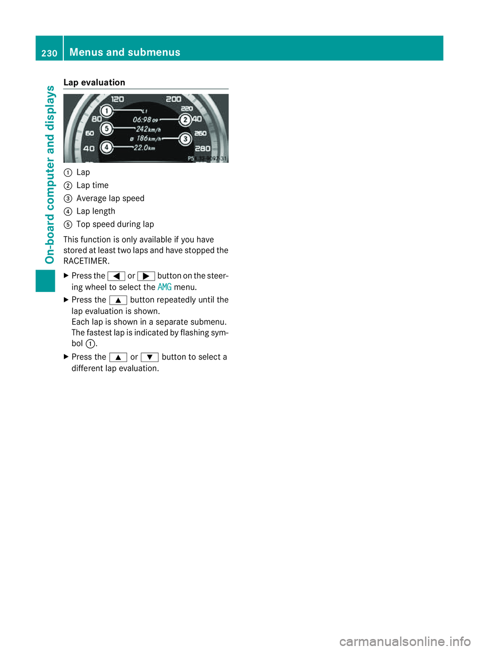
:
Lap
; Lap time
= Average lap speed
? Lap length
A Top speed durin glap
This function is only available if you have
stored at least two laps and have stopped the
RACETIMER.
X Pres sthe = or; button on th esteer-
ing wheel to selec tthe AMG menu.
X Press the 9button repeatedly until the
lap evaluation is shown.
Each lap is shown in aseparate submenu.
The fastest lap is indicated by flashing sym-
bol :.
X Press the 9or: button to select a
different lap evaluation. 230
Menus and submenusOn-board computer and displays
Page 321 of 373
Otherwise, the vehicle's electronic sys-
tem may be damaged.
R in vehicles with automatic transmission,
the transmission is locked in position P
after disconnecting the battery. The vehi-
cle is secured against rolling away. You
can then no longer move the vehicle.
The battery and the cover of the positive
terminal clamp must be fitted securely dur-
ing operation.
In order for the battery to achieve the maxi-
mum possibles ervice life, it must always be
sufficiently charged.
The vehicle battery, like other batteries, can
discharge over time if you do not use the
vehicle. In such cases, have the battery dis-
connected at aqualified specialist workshop.
You can also charge the battery with a
charger recommended by Mercedes-Benz.
For more information, please contact aquali-
fied specialist workshop.
Have the battery charge checked more fre-
quently if you use the vehicle mainly for short
trips or if you leave it standing idle for a
lengthy period. Consult aqualified specialist
workshop if you wish to leave your vehicle
parked up for along period of time.
i When you park the vehicle, remove the
key if you do not require any electrical con-
sumers. The vehicle will then use very little
energy, thus conserving battery power.
i After an interruption of the power supply,
e.g. the battery was discharged, you have
to:
R set the clock. Information on setting the
clock can be found in the separate oper-
ating instructions.
On vehicles with COMAND Online and a
navigation system, the clock is set auto-
matically.
R reset the function for folding the exterior
mirrors in/out automatically, by folding
the mirrors out once (Y page 106). Charging the battery
G
WARNING
Only charge the battery in awell-ventilated
area. As the battery is being charged, gases
can escape and generate minor explosions.
This could injure you and other persons or
cause damage to the paintwork or acid cor-
rosion on the vehicle.
You can obtain information on battery charg-
ers which allow the battery to be charged
while still installed from aqualified specialist
workshop. G
WARNING
There is arisk of acid burns during the charg-
ing process due to the gases which escape
from the battery. Do not lean over the battery
during the charging process. G
WARNING
Battery acid is caustic. Avoid contact with the
skin, eyes or clothing.
! Only charge the installed battery with a
battery charger which has been tested and
approved by Mercedes-Benz.T hese battery
chargers allow the battery to be charged
while still installed in the vehicle.
! Only use battery chargers with amaxi-
mum charging voltage of 14.8 V.
! Only charge the battery using the jump-
start connection point.
The jump-starting connection point is in the
engine compartment( Ypage 319).
Read the battery charger's operating instruc-
tions before charging the battery.
X Open the bonnet (Y page 296).
X Connect the battery charger to the positive
terminal and earth point in the same order
as when connecting the donor battery in
the jump-starting procedure
(Y page 319). 318
Battery (vehicle)Breakdown assistance
Page 322 of 373
Jump-starting
G
WARNING
There is arisk of acid burns when jump-starting avehicle due to the gases which escape from
the battery. Do not lean over the battery while the engine is being jump-started. G
WARNING
Gases escaping from the battery during jump-starting may cause minor explosions. Avoid cre-
ating sparks. Keep naked flames away from the battery, and do not smoke.
Comply with the important safety precautions when handling batteries. You will find these under
"Battery (vehicle) -important safety notes" in the index. G
WARNING
Non-combusted fuel can collect in the exhaust system and ignite. There is arisk of fire. Avoid
repeated and lengthy starting attempts.
! Vehicles with apetrol engine: avoid repeated and length ystarting attempts. Otherwise,
th en on-combusted fuel may damage th ecatalytic converter.
Do not use arapid chargin gdevic etos tart th evehicle. If your vehicle's batter yisdischarged,
the engin ecan be jump-started from another vehicle or from asecon dbatter yusing jump
leads. Observe the following points:
R The batter yisnot accessible in all vehicles. If the other vehicle's batter yisnot accessible,
jump-start the vehicle using asecond battery or ajump-starting device.
R vehicles with apetrol engine: onlyjump-star tthe vehicle when the engine and exhaust
system are cold.
R do not start the engine if the battery is frozen.L et the battery thaw first.
R jump-starting may only be performed from batteries with anominal voltage of 12 V.
R only use jump leads that have asufficient cross-section and insulated terminal clamps.
R if the battery is fully discharged, leave the battery that is being used to jump-start connected
for afew minutes before attempting to start. This charges the empty battery alittle.
R make sure that the two vehicles do not touch.
Make sure that:
R The jump leads are not damaged.
R Non-insulated parts of the terminal clamps do not come into contact with other metal parts
while the jump leads are connected to the battery.
R the jump leads cannot come into contact with parts such as the V-belt pulleyort he fan.
These parts move when the engine is started and while it is running.
X Firmly depress the parking brake.
X Shift the transmission to position P.
X Switch off all electrical consumers (e.g. radio, blower, etc.).
X Open the bonnet (Y page 296).
Position number Bidentifies the charged battery of the other vehicle or an equivalent jump-
startingd evice. Jump-starting
319Breakdown assistance Z