2012 MERCEDES-BENZ CLS COUPE service reset
[x] Cancel search: service resetPage 8 of 373

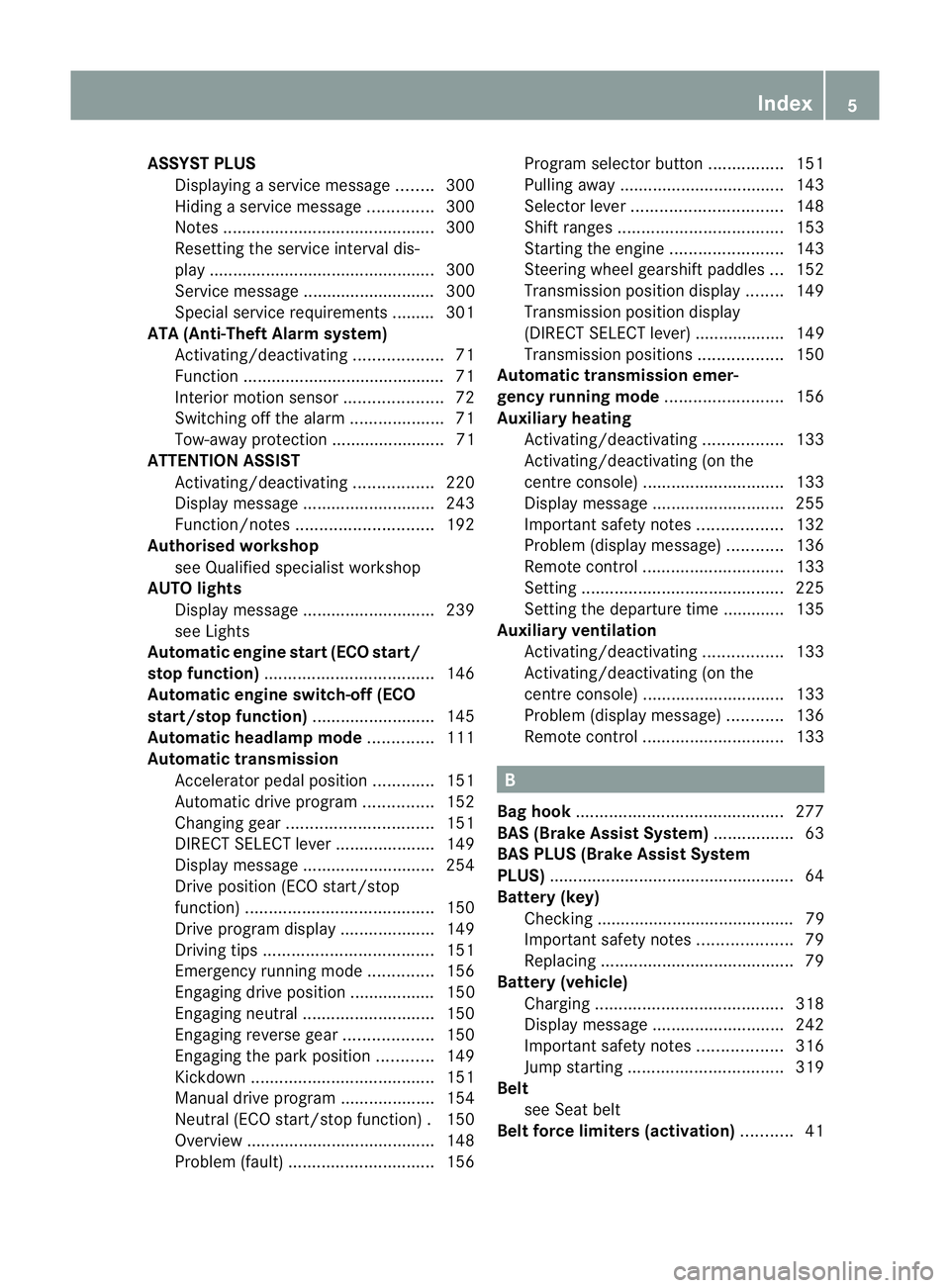
ASSYS
TPLUS
Displaying aservice message ........300
Hiding aservice message ..............300
Notes ............................................. 300
Resetting the service interva ldis-
pla y................................................ 300
Service message ............................ 300
Specia lservice requirements ......... 301
ATA (Anti-Theft Alarm system)
Activating/deactivating ...................71
Function .......................................... .71
Interior motion sensor .....................72
Switching off the alarm ....................71
Tow-awa yprotectio n........................ 71
ATTENTIO NASSIST
Activating/deactivating .................220
Display message ............................ 243
Function/notes ............................. 192
Authorised workshop
see Qualified specialist workshop
AUTO lights
Display message ............................ 239
see Lights
Automatic engine start (ECO start/
stop function) .................................... 146
Automatic engine switch-off (ECO
start/stop function) ..........................145
Automatic headlamp mode ..............111
Automatic transmission Accelerator pedal position .............151
Automatic drive program ...............152
Changing gea r............................... 151
DIRECT SELECT leve r..................... 149
Display message ............................ 254
Drive position (ECO start/stop
function) ........................................ 150
Drive program displa y.................... 149
Driving tips .................................... 151
Emergency running mode ..............156
Engaging drive position .................. 150
Engaging neutra l............................ 150
Engaging revers egear ................... 150
Engaging the par kposition ............ 149
Kickdow n....................................... 151
Manual drive program ....................154
Neutral (ECO start/stop function) .150
Overview ........................................ 148
Problem (fault) ............................... 156Progra
mselector button ................151
Pulling away ................................... 143
Selector leve r................................ 148
Shift range s................................... 153
Starting the engine ........................143
Steering wheel gearshift paddle s... 152
Transmission position displa y........ 149
Transmission position display
(DIREC TSELECT lever) ................... 149
Transmission positions ..................150
Automatic transmission emer-
gency runnin gmode ......................... 156
Auxiliary heating Activating/deactivating .................133
Activating/deactivating (on the
centre console ).............................. 133
Display message ............................ 255
Important safety notes ..................132
Problem (display message) ............136
Remote control .............................. 133
Setting ........................................... 225
Setting the departur etime ............ .135
Auxiliary ventilation
Activating/deactivating .................133
Activating/deactivating (on the
centre console ).............................. 133
Problem (display message) ............136
Remote control .............................. 133 B
Bag hook ............................................ 277
BAS (Brake Assist System) .................63
BAS PLU S(Brake Assist System
PLUS) .................................................... 64
Battery (key) Checking .......................................... 79
Important safety notes ....................79
Replacing ......................................... 79
Battery (vehicle)
Charging ........................................ 318
Display message ............................ 242
Important safety notes ..................316
Jump starting ................................. 319
Belt
see Seat belt
Belt force limiters (activation) ...........41 Index
5
Page 17 of 373

Mirror
see Vanity mirror (in sun visor)
Mirrors
see Exterior mirrors
see Rear-view mirror
Mobile phone
Frequencies ................................... 357
Installatio n..................................... 357
Menu (on-board computer) ............217
Notes/placing in the bracket ......... 284
Sliding adapter ............................... 286
Transmission output (maximum ).... 357
Modifying the programming (key) .....78
MOExtende dtyres ............................ .313
Motorway mode ................................ 115
MP3 Operating ...................................... .216
see Separate operating instructions
Multifunctio ndisplay
Function/notes ............................. 211
Permanent displa y......................... 221
Multifunctio nsteering wheel
Operating the on-board computer .210
Overview .......................................... 33N
Navigation Menu (on-board computer) ............214
NECK-PRO head restraints
Operation ........................................ .46
Resettin gafter bein gtriggered ........47
NECK-PRO luxury head restraints
Operation ........................................ .46
Resettin gafter bein gtriggered ........47
Night View Assist Plus
Activating/deactivating .................195
Cleaning ......................................... 305
Function/notes ............................. 194
Problem (fault) ............................... 197
Notes on runnin ginanew vehicle ..140 O
Occupant safety Childre ninthe vehicle ..................... 52
Important safety notes ....................40
Odometer
see Total distance recorder
see Trip meter
Oil
see Engine oil
On-board computer
AMG menu ..................................... 228
Assistance menu ........................... 218
Audi omenu ................................... 215
Convenience submenu ..................226
Displaying aservice message ........300
Display messages ..........................231
DISTRONI CPLUS ........................... 176
Factory setting submenu ...............227
Heating submenu ........................... 225
Important safety notes ..................208
Instrument cluster submenu ..........221
Ligh tsubmenu ............................... 222
Menu overview .............................. 212
Message memory .......................... 231
Navigation menu ............................ 214
Operating the TV ............................ 216
Operating vide oDVD ..................... 216
Operation ....................................... 210
RACETIMER ................................... 228
Service menu ................................. 220
Settings menu ............................... 221
Standard displa y............................ 212
Telephone menu ............................ 217
Trip menu ...................................... 212
Vehicle submenu ........................... 224
Operatin gsystem
see On-board computer
Outside temperature display ...........210
Overhead control panel ......................37
Override feature Rea rside windows ........................... 62 P
Pain tcode .......................................... 359
Paintwork (cleaning instructions) ...303
Pani calarm .......................................... 4014
Index
Page 26 of 373

fore be carrie
dout at aqualifie dspecialist
workshop. G
WARNING
If work on electronic equipmen tand its soft-
ware is carried out incorrectly, this equipment
could stop working .The electronic systems
are networked via interfaces. Tampering with
these electronic systems could cause mal-
functions in systems which have not been
modified. Malfunctions such as these can
seriously jeopardise the vehicle's operating
safety and therefore your own safety.
You should therefore have all work and mod-
ifications to electronic components carried
out at aqualified specialist workshop. Declarations of conformity
Wireless vehicle components The following information applies to all com-
ponentsoft he vehicle and the COMAND sys-
tem which receive and/or transmit radio
waves:
The components of this vehicle which receive
and/or transmit radio waves are compliant
with the basic requirements and other rele-
vant provisions of Directive 1999/5/EC. You
can obtain further information from any
Mercedes-Ben zService Centre.
Electromagnetic compatibility The electromagnetic compatibility of the vehi-
cle components has been checked and certi-
fied according to the currently valid version
of Directive 72/245/EEC or the equivalent
ECE Regulation ECE-R1 0.Diagnostics connection
G
WARNING
If you connect equipment to adiagnostics
connection, it can affect the operation of the
vehicle systems. This could compromise the operating safety of your vehicle while driving.
There is
arisk of an accident.
Do not connect any equipment to adiagnos-
tics connection. G
WARNING
Loose equipment or cables hanging from a
device which are connected to adiagnostic
connection could impede pedal clearance.
The equipment or cables could get caught
between the pedals when driving and braking
suddenly. This could impair the function of the
pedals. There is arisk of accident.
Do not attach any equipment or cables in the
driver's footwell.
! If the engine is switched off and equip-
ment on the diagnostics connection is
used, the starter battery may discharge.
The diagnostics connection is only intended
for the connection of diagnostic equipment at
aq ualified specialist workshop.
Connecting equipment to the diagnostics
connection can lead to emissions monitoring
information being reset, for example. This
may lead to the vehicle failing to meet the
requirements of the next emissions test dur-
ing the main inspection. Qualified specialist workshop
Aq ualified specialist worksho phas th enec-
essary special skills, tools and qualifications
to correctl ycarry out any necessary work on
your vehicle. This particularly applie stowork
relevan ttosafety.
Observe the notes in the Servic eBooklet.
Always have the following work carried out at
aq ualified specialist workshop:
R work relevant to safety
R service and maintenance work
R repair work
R modifications ,installations and conver-
sions
R work on electronic components Introduction
23 Z
Page 303 of 373

The washer fluid reservoir is used for both the
windscreen washer system and the headlamp
cleaning system.
Further information on windscreen washer
fluid/antifreeze (Y page 366).Service
ASSYST PLUS
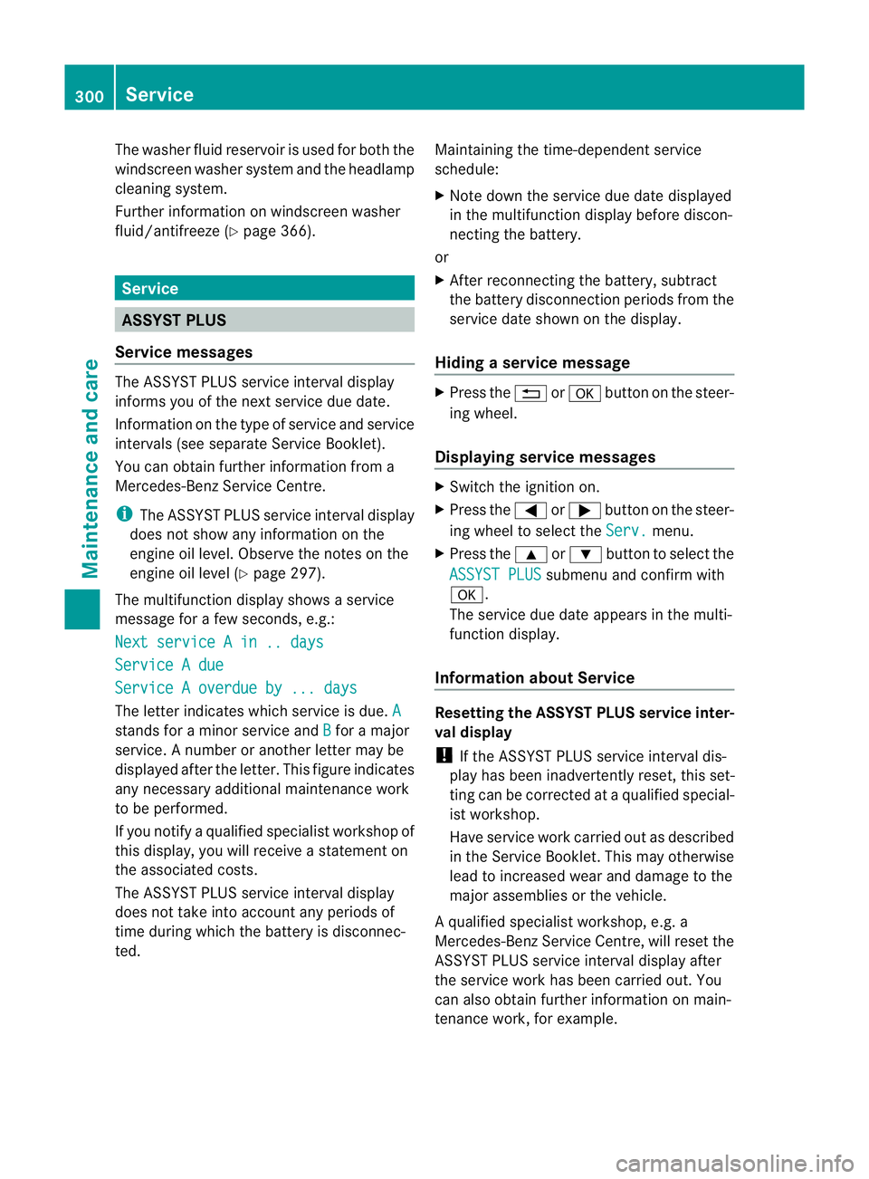
Service messages The ASSYST PLUS service interval display
inform syou of the next service due date.
Information on the type of service and service
intervals (see separate Servic eBooklet).
You can obtain further information from a
Mercedes-Benz Servic eCentre.
i The ASSYST PLUS service interval display
does not show any information on the
engine oil level. Observe the notes on the
engine oil level (Y page 297).
The multifunction display shows aservice
message for afew seconds, e.g.:
Next service Ain..days Service
Adue Service
Aoverdue by ... days The letter indicates which service is due.
Astands for
aminor service and B for
am ajor
service. Anumber or another letter may be
displayed after the letter .This figure indicates
any necessary additional maintenancew ork
to be performed.
If you notify aqualified specialist workshop of
this display, you will receive astatementon
the associated costs.
Th eA SSYS TPLUSs ervice interval display
does not take intoa ccountany periods of
time during which the battery is disconnec-
ted. Maintaining the time-dependent service
schedule:
X Note down the servic eduedate displayed
in the multifunctio ndisplay befor ediscon-
nectin gthe battery.
or
X After reconnecting the battery, subtract
the battery disconnection periods fro mthe
service date shown on the display.
Hiding aservice message X
Pres sthe % ora button on th esteer-
ing wheel.
Displaying service messages X
Switch th eignitio non.
X Press the =or; button on the steer-
ing whee ltoselect the Serv. menu.
X Press the 9or: button to select the
ASSYST PLUS submenu and confirm with
a.
The servic eduedate appear sinthe multi-
functio ndisplay.
Information about Service Resetting th
eASSYST PLUS service inter-
val display
! If the ASSYS TPLUS service interval dis-
play has been inadvertently reset ,this set-
tin gc an be corrected at aqualified special-
ist workshop.
Have service work carried out as described
in the Servic eBooklet. This may otherwise
lead to increased wear and damage to the
major assemblies or the vehicle.
Aq ualified specialist workshop, e.g. a
Mercedes-Ben zService Centre, will reset the
ASSYST PLUS servic einterval display after
the servic ework has been carried out. You
can also obtain further information on main-
tenance work, for example. 300
ServiceMaintenance and care