Page 217 of 342

.. Make sure that each of the two guidance fix
tures per seat snaps into p lace.
Rem oving the guidance fi xture s
.. Remove the child restrai nt according the
child restra int manufacturer's instruct ions .
.. Push down on the seat cushion so that the
lower anchorages are visib le .
.. Pull
off the guida nee fix t u res from the low
er anchorages.
.,. Always remove the guidance fixtures and
keep them in a safe place when not in use.
You may find it easier to install child re
straints equipped with hooks attached to
straps without the guidance f ixtures in place.
If this is the case, remove the guidance fix
tures by pull ing them
off the anchorages .
H owever, the guidance fixtures can he lp you
to locate the
LATCH anchorages.
_& WARNING
Improper use of tether anchorages or low
er anchorages can cause serious personal
injury in a crash .
- Always carefully follow the ch ild re
straint manufacturer 's instruct ions for
proper installation and use of child re
straint systems.
- Never use the
LATCH or tether anchorag
es to attach safety belts o r other kinds of
occupant restraints .
- Child restraint tether attachments and
lower attachments are only designed to
secure a child restraint that has been equipped to use these anchorages.
- Tether anchorages and lower anchorages
are designed to withstand only those
loads imposed by correctly fitted chi ld
restraints. Under no circumsta nces can
they be used safely for adu lt or chi ld
safety belts o r harnesses .
- Never mount more than one ch ild re
st raint to a sing le tether or to a lower an
cho rage point. Attach ing two ch ild re
st raints to a single anchorage point can
ca use the anchorage to fail and cause se
rious persona l injury in a crash .
Child Safety 215
(D Note
-Remove the g uidance fixtures before
folding the rear seatback to prevent damaging the seat cushion .
- If you leave the guidance f ixtures instal
led for several days , they could leave a
mark on the upholstery on the seat cush
ion and backrest in the area that the
guidance fixtures were installed . The up
holstery would also be permanently
st retched a round the guidance fixtures.
T hi s app lies especia lly to leather seats.
Installing a child restraint with LATCH
lower anchorages
Whenever you install a child restraint always
follow the child restraint manufacturer's in
structions.
F ig. 213 Lowe r anc horages : prope r mount ing
Mountin g
.. Make sure the seatback of the rear seat
bench is in t he upright position and securely
latched in place .
.. Attach both hook-on co nnectors with the
spring catch release on the child safety seat
onto the LATCH lower anchorage so that the
connecto rs lock into place
~ fig. 213.
.. Pull on the connector attachments to make
sure they are properly attached to the LATCH
lower ancho rage .
.. Pull straps tight fo llowing the child re
straint manufacturer's instructions.
Relea sing
.. Loosen the tension on the straps following
the child restraint manufact urer's instruc
tions .
Page 218 of 342

216 Child Safety
• Depress the spring catches to re lease the
anchorage hooks from the lower anchorag
es.
Remember: Use tether straps to help keep the
child restraint firmly in place.
A WARNING
Improper use of the LATCH system can in
crease the risk of ser ious personal injury
and death in an accident.
- These anchors were developed only for
child safety seats using the "LATCH" sys
tem.
- Never attach other child safety seats,
belts or other objects to these anchors.
- Always make sure that you hear a click
when latching the seat in place. If you do
not hear a click the seat is not secure and
could fly forward and hit the interior of
the vehicle, or be ejected from the vehi
cle.
A WARNING
Improper insta llation of chi ld restraints
w ill increase the risk of injury in an acci
dent.
- Always follow the child restraint system
man ufactur er's instr uctions for proper
installation of the child restraint system
and proper use of tether straps as we ll as
the lower anchorages or safety belts in
your vehicle.
-Always read and heed the important in
format ion and WARNINGS about child
safety and the installation of child re
straint systems¢
page 200, Child Safe
ty.
-
Tether anchors and tether straps
Fig. 214 T ether ancho rs for second row of seats: at
tachment hook locations
Fig. 21S Tether anchors fo r th ird row of seats: attach
m ent hook lo cations
T he tether anchors for the three rear seating
positions in the second row of seats are locat
ed underneath the seats in the back
<=? fig. 214. For vehicles with third row seat
ing*, the tether anchors for the two seating
pos itions in the third row of seats are stored
underneath a plastic cover cap in the floor
<=?fig. 215.
A tether is a stra ight or V-shaped strap that
attaches the top part of a ch ild restra int to
special anchorage po ints in the vehicle.
The purpose of the tether is to reduce the for
ward movement of the child restraint in a
crash, in order to help reduce the risk of head
injury that could be caused by striking the ve
hicle interior.
Forward facing child restraints manufactured
after September 1, 1999, are required by U.S.
federal regulations to comply with new child
head movement performance requirements.
T hese new performance requirements make a
tether necessary on most new child safety
seats.
Page 219 of 342

_& WARNING
Improper installation of child restraints
w ill increase the risk of injury and death in
a crash .
- Always follow the instructions prov ided
by the manufacturer of the ch ild re
st raint you intend to install in your Audi.
- Improper use of ch ild restraint anchors
(including tether anchors) can lead to in
jury in a co llision. The anchors are de
signed to withstand only those loads im
posed by correct ly fi tted ch ild restraints.
- Never mount two child restrai nt systems
on one LA TCH lowe r ancho r po int.
- Never attach two child restraint systems
to one tethe r strap or te ther anchorage.
- Never attach a tether st rap to a tie-down
hook in the luggage compartment.
- Never use ch ild restra int tether ancho
rages to secur e safety belts o r other
k inds of o ccupant rest ra ints.
- Never secure o r attach any l uggage or
other items to the LATCH lowe r ancho
rages or to t he tethe r ancho rs.
- If a tether o r othe r strap is used to at
ta ch a child rest raint to the front passen
ger seat, make sure that it is not so
t ight, th at it c auses the weigh t-sensing
mat to measure mo re weig ht than is ac
t u ally on the seat.
- T he heav ier we ig ht reg iste red can make
the Advanced Airbag System work as
though an ad ult were on the seat and de
ploy the Advanced Airbag w hen it must
be suppressed causing serious or even
fatal injury to the child .
- If you must install a rearward facing child safety seat on the front passenger
seat beca use of exceptional circ umstan
ces and the
PASSENGER AIR BAG OFF
light does not come on and stay on, im
med iate ly install the rear -facing child
sa fety seat in a rear seating posi tion and
have the a irbag sys tem inspec ted by you r
Audi dealer .
Child Safety 21 7
Installing the upper tether strap on the
anchorage
Fig . 21 6 Tet her s trap: prope r rout ing a nd m ounti ng
Fi g. 217 Tet her st rap fo r seco nd row se ats: prope r
rou ting and moun tin g
Installing the tether strap
... Release or deploy the tether strap on the
child res traint accord ing to the child re
st raint manufacture r's ins tructions .
... Guide the upper tether strap
und er the rear
head restraint and into the rear ca rgo area
(raise the head restraint if necessary) .
... Fo r the second row o f seats: Pull the floor
ing back, in order to reach the anchor brack
et
c:::> fig. 217 .
... For the third row of seats :* Remove the
plastic cover cap with a screw drive r, in orde r
t o reach the anchor bracket
c:::> page 216,
fig . 215.
... Slide the tether s trap hoo k over the anchor
bracket .
... Pull on the tether strap hook so that the
spring catch of the hook engages .
.,. Tighten the tether strap firmly fo llow ing
the child restra int manufacturer's instruc
tions.
.,. For the second row of seats: Push the floor
ing forward into place again.
Page 220 of 342

218 Child Safety
Releasing the tether strap
.. Loosen the tension following the child re
straint manufacturer's instructions.
.. Depress the spring catch on the hook and
release it from the anchorage.
.. For the second row of seats: Push the floor
ing forward into place again.
.. For the third row of seats:* Replace the
plastic cover cap .
(D Note
If you leave the child restraint with the
tether strap firmly installed for several
days, this could leave a mark on the up
holstery on the seat cushion and backrest
in the area where the tether strap was in
stalled. The upholstery would also be per
manently stretched around the tether
strap. This applies especially to leather
seats.
Using tether straps on rearward-facing
child restraints
Currently , few rear -facing child restraint sys
tems come with a tether . Please read and
heed the child restraint system manufactur
er's instructions carefully to determine how to
properly install the tether.
& WARNING
A child in a rearward-facing child safety
seat installed on the front passenger seat
will be seriously injured and can be killed if
the front airbag inflates - even with an Ad
vanced Airbag System.
- The inflating airbag will hit the child safety seat or infant carrier with great
force and will smash the child safety seat and child against the backrest, center
armrest, or door .
- A tight tether or other strap on a rear
ward-facing child restraint attached to
the front passenger seat can put too much pressure on the weight-mat in the
seat and register a heavier weight in the
Advanced Airbag System. The heavier weight
registered can make the system
work as though an adult were on the seat
and deploy the Advanced Airbag when it
must be suppressed causing serious or
even fatal injury to the child.
- If you must install a rearward facing
child safety seat on the front passenger
seat because of exceptional circumstan
ces and the
PASSENGER AIR BAG OFF
light does not come on and stay on, im
mediately install the rear-facing child
safety seat in a rear seating position and
have the airbag system inspected by your
Audi dealer.
Additional Information
Sources of information about child
restraints and their use
There are a number of sources of additional
information about child restraint selection, in
stallation and use:
NHTSA advises that the best child safety seat
is the one that fits your child and fits in your
vehicle, and that you will use correctly and
consistently.
Try before you buy!
U.S National Highway Traffic Safety Admin
istration
Tel.: 1-888-327-4236 (TIY: 1-800-424-9153)
http://www.nhtsa.gov
National SAFE KIDS Campaign
Tel.: (202) 662-0600
http://www.safekids .org
Safety BeltSafe U.S.A
Tel.: (800) 7 45 -SAFE (Eng Lish)
Tel.: (800) 747-SANO (Spanish)
http://www.carseat.org
Transport Canada Information Centre
Tel.: 1-800 -333-0371 or call
1-613-998-8616 if you are in the Ottawa area
http://www.tc.gc.ca/eng/roadsafety/
menu.htm
Audi Customer Relations
Tel.: (800) 822-2834
Page 221 of 342
, installed by some manu
facturers fo")
Intelligent technology Notice about data
recorded by vehicle
control modules
Your vehicle is not equipped with an Event Da
ta Recorder (EDR), installed by some manu
facturers for the express purpose of capturing
data for retrieval after an accident or crash
event. EDRs are sometimes called "crash re
corders".
Some state laws restrict the retr ieval or down
loading of data stored by EDRs that were in
stalled in a vehicle for the express purpose of
retrieving data after an accident or crash
event without the owner's consent.
Although your vehicle is not equipped with an
EDR, it is equipped with a number of electron
ic control modules for various vehicle systems
such as, for example, engine function, emis
sion control, as well as for the airbags and
safety belts.
These electronic control modules also record
vehicle-related data during norma l vehicle op
eration for diagnostic and repair purposes.
The recording capacity of the electronic con
trol modules is limited to data (no sound is re
corded) and only a small amount of data is ac
tually recorded over a very limited period of
time and stored when a system fault or other
condition is sensed by a control unit. Some of
the data then stored may relate to vehicle
speed, direction, braking as we ll as restraint
system use and performance in the event of a
crash or other condition. Stored data can only be read and downloaded with special equip
ment.
Intelligent technology 219
Electronic Stability
Control (ESC)
General information
The ESC improves the vehicle stability.
. ..---------..
------- -
Fig. 218 Center console with ESC sw itch
ESC is designed to help you maintain vehicle
control in situations where the car approaches
the limits of "grip", especially when accelerat
ing and cornering. ESC reduces the risk of
skidding and improves stability under all road
condit ions .
The system operates across the entire speed range in combination with the ABS system. If
the Anti-Lock Brake System (ABS) malfunc
tions, the ESC will also shut down.
How the system works
The Anti-Lock Brake System (ABS), Electronic
Differential Lock (EDL) and the Anti-Slip Regu
lation System (ASR) are integrated in the Elec
tronic Stability Control. In addition to the da
ta provided by these functions, the ESC con
trol unit requires additional measurement da
ta provided by high performance sensors. The
rotational speed of the vehicle about its verti
cal axis, vehicle acceleration in the fore-and
aft and lateral directions, the brake pressure and the steering angle are all measured.
T he direction in wh ich the driver wishes to
travel is determined with the aid of the steer
ing angle and vehicle speed and is continually
compared with the actua l behavior of the ve
hicle. If the two do not match, for example,
when the vehicle starts hydroplaning on a wet
road, ESC will automatically brake the appro-
priate wheel to correct the problem. ..,_
•
•
Page 222 of 342

220 Intellig ent technol ogy
The vehicle is then stabilized by the forces act
ing on the whee l during braking. If the vehicle
is
oversteering (rear tends to sk id out of the
turn), the brakes are ma inly applied on the
wheel that is on the outside of the curve. In
the case of a vehicle that is
understeering
(tendency to slide out of the curve), the
brakes are applied as needed on the whee l
that is on the ins ide of the curve or addit ional
l y on the o ther wheels. An acoustic s ignal indi
cates when ESC b rake app lication cuts in
¢ A .
The system operates across the entire speed
range in combination with the ABS system
¢ page 223. If the Anti-Lock Brake System
(ABS) malfunctions, the ESC wi ll be out of ac
tion as well .
Activating
When you turn on the engine, ESC w ill auto
mat ica lly be act ivated and will perform a se lf
test. As soon as the test is comp leted, the sys
tem is in normal operating mode.
Offroad mod e
ESC should normally be ope rated in normal
mode because this ensures maximum vehicle
stability. If necessary, you can act ivate the
ESC offroad mode by pressing the but to n
¢ fig . 218 to obtain maximum traction and
braking ability when driving
off paved roads at
l ow speeds. In ESC offroad mode, the indica
tor light
fi illuminates and the message Off
road control Warning! Red uced t ract ion
ap
pears briefly in the display .
The ESC offroad mode can be usefu l in the fo l
low ing except iona l situations when slip or a
h ighly effective differentia l locking function is
desirable . Examples:
- when driving with tire chains,
- when driving in deep snow or on loose
ground,
- when driving on uneven surfaces with the
wheels severe ly unloaded (articulation), and
- when rocking the vehicle loose after it has
become stuck.
When the unusua l situat ion is past, you
should shift back to the normal ESC operating mode by pushing the button again
. The mes
sage
S tabilit y prog ram on then appears brief
l y in the display.
H ill descent control
T he hill descent con trol is swi tched on in ESC
offroad mode . When slowly descending steep
gradients on loose gro und or when the axles
are articulated, hill descent control provides
ass istance by automatically applying the
brakes to keep vehicle speed constant. The ve
hicle is also rendered easier to steer by selec
t ive d istr ibut ion of braking force . H ill descent
control intervenes when:
- the acce lerator pedal is not pressed,
- the vehicle is travelling less than 12 mph
(20 km/h),
- a steep gradient is detected,
- wheel behavior indicates loose ground or
conditions with poor adhesion (e.g . a lso axle
articu lation).
Hill descent con tro l operates both d riving for
ward and in reverse. Active hill descent con
trol is deactivated by pressing the accelerator
pedal unti l the conditions for activation al
ready listed are met again.
A WARNING
- The Electronic Stability Control is never
theless subject to the laws of phys ics. It
is part icu larly important to pay attention
to this fact on wet and slippery roads. It is therefore impo rtant that you a lways
a dapt your d riving to the condit ion of the
road and traffic cond itions. Do not allow
the increased safety provided by the Electron ic Stability Control system to lull
you into accepting additional safety
risks.
- Please be aware that in ESC offroad
mode, particularly on a smooth and s lip
pery road, the wheels may have an in
creased tendency to spin and the vehicle
may break away - danger of skidding!
- Stability is limited in the ESC offroad
mode.
Page 223 of 342

The electronic differential lock monitors the
rotational speed of the drive wheels.
G ener al note s
The electronic differentia l lock (EDL) helps th")
Electronic differential lock (EDL)
The electronic differential lock monitors the
rotational speed of the drive wheels.
G ener al note s
The electronic differentia l lock (EDL) helps the
car to start mov ing, accelerate and climb a
gradient on surfaces providing poor or almost
no gr ip . W ithout EDL, this would be difficult,
if not impossible .
How the s yst em work s
The EDL operates automatically . It monitors
the rotat ional speed of wheels w ith the help
of the ABS sensors <=>
page 223. If a noticea
ble
slip i s detected at the wheels (e.g . on slip
pery ground
on one side), the spinning wheels
are braked and power is transferred to the
other wheels. This is done up to a speed of
about 60 mph (100 km/h). Noises from the b rake system signal that wheel spin is being
contro lled .
Driving off
When driv ing off , a lways be sure to keep road
conditions in mind as you accelerate . If one
drive whee l spins because it is on a surface
with less grip, apply
plenty of throttle until
the car starts to move.
Overheating of brakes
To prevent the disc brake of the b raked wheel
from ove rheating if subjected to excessive
l oads on this whee l, the EDL cuts out tempo
ra rily. The vehicle remains operational and be
h aves in the same way as a vehicle without
EDL.
As soon as the brake has cooled down, EDL
switches on again automatically .
A WARNING
-When accelerating on slippery surfaces,
such as on ice or snow, always be careful
when depressing the acce lerator pedal.
Even with the EDL working, the drive
wheels can spin and reduce your ability
to control your car . R isk of crash!
Int ellig ent technolog y 221
-The increased safety afforded by EDL
does not mean that you can take safety
risks. Always adapt your driving style to
the road condit ions and traffic situation .
(!) Tips
If a fault occurs in the ABS, the EDL is also
not functioning. This is ind icated by the
ABS warning light <=>
page 18.
' Anti-Slip Regulation System (ASR)
The Anti-Slip Regulation System prevents the
driven wheels from spinning when the car is
accelerating.
G eneral not es
The Anti-Slip Regulation System (ASR) is inte
grated in the Electronic Stability Control
(ESC). When the vehicle starts up and acceler
ates, the wheels are prevented from spinning
by adjust ing the eng ine power to match the
amount of grip available from the road sur
face .
How the system works
ASR performs automatica lly, i.e. without the
driver 's intervention. With the aid of the ABS
sensors <=>
page 223, ASR monitors the speed
of the dr iven wheels. If the wheels start to
spin, engine torque is reduced automatically
unt il the t ires find enough grip to lock onto
the road surface. The system is active across
the enti re speed range.
The ASR works in conjunction with the ABS. If
a malfunction should occur in the ABS, the
ASR wi ll also be ou t of act ion.
A WARNING
The increased safety affo rded by ASR does
not mean that you can take sa fety risks.
A lways adapt your driving sty le to the road
conditions and traffic situation. ...,
•
•
Page 224 of 342

222 Intelligent technology
To ensure that the ASR works properly, all
four wheels must be fitted with identical
tires. Any differences in rolling rad ius of
the t ires can cause the system to reduce
engine power when this is not desired. See
also¢
page 285, New tires and replacing
tires and wheels.
Braking
General information
What affects braking efficiency?
Operating conditions and driving habits
The brakes on today's automob iles are st ill
subject to wea r, depending la rgely on operat
ing cond itions and dr iv ing habits
Q ,& . On ve
hicles that are eithe r driven mostly in stop
and -go city traffic or are driven hard, the
brake pads should be checked by your author
ized Audi dealer more often than specified in
the
Warranty & Maintenance booklet . Failure
to have your brake pads inspected can result
in reduced brake performance .
On steep slopes, you shou ld use the braking
effect of the engine. This way, you prevent un
necessary wear on the brake system. If you
must use your brakes, do not hold the brakes
down continuously . Pump the brakes at inter
va ls.
Noises may occur when braking depending on
the speed, braking force and outside condi
tions such as temperature and humidity.
Moisture or road salt
Under certain conditions, for examp le, when
driving through water or very heavy rain, or
even after washing your vehicle, the braking
effect can be reduced due to moisture (or in
freezing conditions ice) on the brake pads. A
few careful brake applications should dry off
the brake pads o r remove any ice coatings.
When you are driving at higher speeds with
the w indshield wipers on, the brake pads will
brief ly touch the brake discs in regular inter- vals so as
to improve reaction time when brak
ing on wet surfaces . You, the driver, will not
notice anything.
T he effect iveness of the brakes can be reduced
when the vehicle is driven on a sa lt-covered
road and the brakes are not used . Here too,
you should clean off accumulated sa lt coating
from brake discs and pads w ith a few careful
applications of the brake¢,&.
Corrosion
There may be a tendency for dirt to build up
on the brake pads and corrosion to form on
the discs if the car is not driven regu larly or
only for short trips w ith litt le use of the
brakes.
If the brakes are not used frequently, or if cor
rosion has formed on the discs, it is advisable
to clean off the pads and discs by braking
firmly a few times from a moderately high
speed
c> ,& .
Faults in the brake system
If you shou ld notice a sudden increase in
brake pedal trave l, then one of the two brake
c ir cuits may have fa iled
c> ,& .
Low brake fluid level
Malfunctions can occur in the brake system if
the brake fluid level is too low. The brake fluid
l evel is monitored electronically .
Brake lining wear status
Brake lining wear may be checked by visual in
spect ion of the condition of the brake pads
through the openings in the wheel. If neces
sary, the wheel may be removed for this in
spect ion
c> page 298, Changing a wheel.
A WARNING
-- You shou ld perform braking maneuvers
for the purpose of cleaning the brake
system only if road conditions permit.
Other road users must not be put at risk -
you may cause an accident!
 1
1 2
2 3
3 4
4 5
5 6
6 7
7 8
8 9
9 10
10 11
11 12
12 13
13 14
14 15
15 16
16 17
17 18
18 19
19 20
20 21
21 22
22 23
23 24
24 25
25 26
26 27
27 28
28 29
29 30
30 31
31 32
32 33
33 34
34 35
35 36
36 37
37 38
38 39
39 40
40 41
41 42
42 43
43 44
44 45
45 46
46 47
47 48
48 49
49 50
50 51
51 52
52 53
53 54
54 55
55 56
56 57
57 58
58 59
59 60
60 61
61 62
62 63
63 64
64 65
65 66
66 67
67 68
68 69
69 70
70 71
71 72
72 73
73 74
74 75
75 76
76 77
77 78
78 79
79 80
80 81
81 82
82 83
83 84
84 85
85 86
86 87
87 88
88 89
89 90
90 91
91 92
92 93
93 94
94 95
95 96
96 97
97 98
98 99
99 100
100 101
101 102
102 103
103 104
104 105
105 106
106 107
107 108
108 109
109 110
110 111
111 112
112 113
113 114
114 115
115 116
116 117
117 118
118 119
119 120
120 121
121 122
122 123
123 124
124 125
125 126
126 127
127 128
128 129
129 130
130 131
131 132
132 133
133 134
134 135
135 136
136 137
137 138
138 139
139 140
140 141
141 142
142 143
143 144
144 145
145 146
146 147
147 148
148 149
149 150
150 151
151 152
152 153
153 154
154 155
155 156
156 157
157 158
158 159
159 160
160 161
161 162
162 163
163 164
164 165
165 166
166 167
167 168
168 169
169 170
170 171
171 172
172 173
173 174
174 175
175 176
176 177
177 178
178 179
179 180
180 181
181 182
182 183
183 184
184 185
185 186
186 187
187 188
188 189
189 190
190 191
191 192
192 193
193 194
194 195
195 196
196 197
197 198
198 199
199 200
200 201
201 202
202 203
203 204
204 205
205 206
206 207
207 208
208 209
209 210
210 211
211 212
212 213
213 214
214 215
215 216
216 217
217 218
218 219
219 220
220 221
221 222
222 223
223 224
224 225
225 226
226 227
227 228
228 229
229 230
230 231
231 232
232 233
233 234
234 235
235 236
236 237
237 238
238 239
239 240
240 241
241 242
242 243
243 244
244 245
245 246
246 247
247 248
248 249
249 250
250 251
251 252
252 253
253 254
254 255
255 256
256 257
257 258
258 259
259 260
260 261
261 262
262 263
263 264
264 265
265 266
266 267
267 268
268 269
269 270
270 271
271 272
272 273
273 274
274 275
275 276
276 277
277 278
278 279
279 280
280 281
281 282
282 283
283 284
284 285
285 286
286 287
287 288
288 289
289 290
290 291
291 292
292 293
293 294
294 295
295 296
296 297
297 298
298 299
299 300
300 301
301 302
302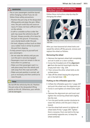 303
303 304
304 305
305 306
306 307
307 308
308 309
309 310
310 311
311 312
312 313
313 314
314 315
315 316
316 317
317 318
318 319
319 320
320 321
321 322
322 323
323 324
324 325
325 326
326 327
327 328
328 329
329 330
330 331
331 332
332 333
333 334
334 335
335 336
336 337
337 338
338 339
339 340
340 341
341