Page 217 of 256

Replacing componentsMOBILITY
215
Stowing Mobility System
1.Unscrew filler hose 2 of the sealant bottle
from the wheel.
2. Unscrew connecting hose of the
compressor 6 from the sealant bottle.
3. Connect the filler hose 2 of the sealant bot-
tle to the unoccupied connection on the
sealant bottle.
This prevents the rest of the sealant from
escaping from the bottle.
4. Wrap the empty sealant bottle in suitable
material to avoid dirtying the cargo area.
5. Stow Mobility System back in the vehicle.
Distributing the sealant
Immediate drive approx. 3.1 miles/5 km so that
the sealant evenly distributes itself.
Do not exceed speeds of 50 mph/
80 km/h.
If possible, do not drop below 10 mph/
20 km/h.<
Adjusting the tire pressure
1. After driving approx. 3.1 miles/5 km or
10 minutes, stop at a suitable location.
2. Screw the connection hose 6 of the com-
pressor directly onto the tire valve.
3. Insert the plug 5 into the power socket in
the vehicle interior.
4. Correct inflation pressu re to 26 psi/180 kPa.
With the engine running:
> To increase the inflatio n pressure: switch on
the compressor. To check the current infla-
tion pressure, switch off the compressor.
Do not run the compressor for longer
than 10 minutes; otherwise, the
device will overheat and possibly be dam-
aged. <
> To decrease the inflation pressure: press the
release button 9. If the tire cannot ma
intain the inflation
pressure, drive the vehicle again, refer to
Distributing the sealan t. Then repeat steps
1to4.
If an inflation pressure of 26 psi/180 kPa still
cannot be reached, the tire is too heavily dam-
aged. Contact the nearest MINI dealer. <
Driving on
Do not exceed the permitted maximum
speed of 50 mph/80 km/h; doing so may
result in an accident.<
Replace the defective tire as soon as possible
and have the new wheel/tire assembly bal-
anced.
Have the Mobility System refilled.
Changing wheels
Run-flat tires*
Tire change for run-flat tires:
> Prepare for tire change, page 216
> Jack up vehicle, page 216
> Tighten lug bolts, page 217
Space-saver spare tire*
Tire change with space-saver spare tire:
>Remove the space-saver spare tire,
page 215
> Prepare for tire change, page 216
> Jack up vehicle, page 216
> Mount space-saver spare tire, page 217
> Tighten lug bolts, page 217
> Drive with space-saver spare tire, page 216
Removing the space-saver spare tire
The space-saver spare tire is located under the
tire change set in the cargo area.
Page 218 of 256

MOBILITYReplacing components
216
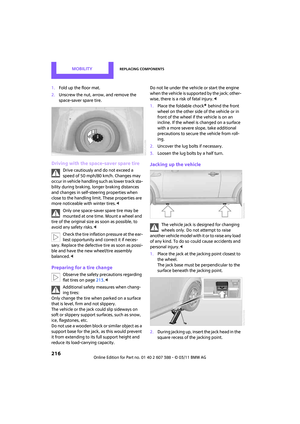
1.Fold up the floor mat.
2. Unscrew the nut, arrow, and remove the
space-saver spare tire.
Driving with the space-saver spare tire
Drive cautiously and do not exceed a
speed of 50 mph/80 km/h. Changes may
occur in vehicle handling such as lower track sta-
bility during br aking, longer braking distances
and changes in self-steering properties when
close to the handling limit. These properties are
more noticeable with winter tires. <
Only one space-saver spare tire may be
mounted at one time. Mount a wheel and
tire of the original size as soon as possible, to
avoid any safety risks. <
Check the tire inflation pressure at the ear-
liest opportunity and correct it if neces-
sary. Replace the defective tire as soon as possi-
ble and have the new wheel/tire assembly
balanced. <
Preparing for a tire change
Observe the safety precautions regarding
flat tires on page 213.<
Additional safety measures when chang-
ing tires:
Only change the tire wh en parked on a surface
that is level, firm and not slippery.
The vehicle or the jack could slip sideways on
soft or slippery support surfaces, such as snow,
ice, flagstones, etc.
Do not use a wooden block or similar object as a
support base for the jack, as this would prevent
it from extending to its full support height and
reduce its load-carrying capacity. Do not lie under the vehicle or start the engine
when the vehicle is supported by the jack; other-
wise, there is a risk of fatal injury.
<
1. Place the foldable chock
* behind the front
wheel on the other side of the vehicle or in
front of the wheel if the vehicle is on an
incline. If the wheel is changed on a surface
with a more severe sl ope, take additional
precautions to secure the vehicle from roll-
ing.
2. Uncover the lug bolts if necessary.
3. Loosen the lug bolts by a half turn.
Jacking up the vehicle
The vehicle jack is designed for changing
wheels only. Do not attempt to raise
another vehicle model with it or to raise any load
of any kind. To do so could cause accidents and
personal injury. <
1. Place the jack at the jacking point closest to
the wheel.
The jack base must be perpendicular to the
surface beneath the jacking point.
2. During jacking up, insert the jack head in the
square recess of the jacking point.
Page 219 of 256

Replacing componentsMOBILITY
217
3.Jack the vehicle up until the wheel you are
changing is raised off the ground.
Mounting the space-saver spare tire
1.Unscrew the lug bolts and remove the
wheel.
2. Remove accumulations of mud or dirt from
the mounting surfaces of the wheel and
hub. Clean the lug bolts.
3. Lift the new wheel into place.
4. Screw at least two lug bolts finger-tight into
opposite bolt holes.
5. Screw in the remaining bolts.
6. Tighten all the lug bolts firmly in a diagonal
pattern.
7. Lower the vehicle.
8. Remove the jack.
Tightening the lug bolts
Tighten the lug bolts in a diagonal pattern.
Immediately have the wheels checked
with a calibrated torque wrench to ensure
that the lug bolts are firmly seated. Otherwise,
incorrectly tightened lug bolts can present a
safety hazard. <
Tightening torque: 103.3 lb ft or 140 Nm.
Replace the defective tire as soon as possible
and have the new wheel/tire assembly bal-
anced.
Vehicle battery
Maintenance
The battery is 100 % maintenance-free, the
electrolyte will last for the life of the battery
when the vehicle is operated in a temperate cli-
mate.
Battery replacement
Only use vehicle batteries that have been
approved for your vehicle by the manu-
facturer; otherwise, the vehicle could be dam-
aged and systems or func tions may not be fully
available. <
After a battery replacement, have the battery
registered on the vehicle by your dealer to
ensure that all comfort functions are fully avail-
able.
Charging the battery
Only charge the battery in the vehicle when the
engine is off. Connection s, refer to Jump-start-
ing on page 219.
Disposal
After replacing old batteries, return the
used batteries to your MINI dealer or to a
recycling center. Maintain the battery in an
upright position for transport and storage.
Always secure the battery against tipping over
during transport. <
Power failure
After a temporary power loss, some equipment
may not be fully functional and may require ini-
tialization. Individual se ttings are also lost and
must be reprogrammed:
> Time and date
These values must be updated, page 63.
> Navigation system
Operability must be waited for, page 108.
> Glass roof
*, electric
It may only be possible to raise the roof, if
applicable. The system must be initialized.
Contact your nearest MINI dealer.
Page 220 of 256
MOBILITYReplacing components
218
Fuses
Do not attempt to repair a blown fuse or
replace it with a fuse of a different color or
Ampere rating. To do this could cause a fire in
the vehicle resulting from a circuit overload.
Have the fuse changed only by a MINI dealer or
a workshop that has specially trained personnel
working in accordance with the specifications of
the MINI manufacturer. <
A fuse allocation diagram is located on the inside
of the fuse box cover panels.
In the engine compartment
Opening the cover
Press the latch.
In the vehicle interior
On the right side of the footwell.
Opening the cover
Press out at the recess.
Page 221 of 256

Giving and receiving assistanceMOBILITY
219
Giving and receiving assistance
Roadside Assistance
Roadside Assistance is available by phone
24 hours a day in many countries. You can
receive assistance there in the event of an emer-
gency.
First aid pouch*
Some of the articles co ntained in the first aid
pouch have a limited se rvice life. Therefore,
check the expiration dates of the contents regu-
larly and replace any items in good time, if nec-
essary.
The first aid pouch is located on the rear cargo
well by the left side trim panel or under the flat
load floor.
Warning triangle*
In the cargo area under the loading sill. Open the center lock to take it out.
Jump-starting
If the car's own battery is flat, your MINI's engine
can be started by connecting two jumper cables
to another vehicle's battery. You can also use
the same method to help start another vehicle.
Only use jumper cables with fully-insulated
clamp handles.
Do not touch any electrically live parts
w hen the e ngin e is run ning, or a fatal acci-
dent may occur. Carefully adhere to the follow-
ing sequence, both to prevent damage to one or
both vehicles, and to guard against possible per-
sonal injuries. <
Preparation
1.Check whether the battery of the other vehi-
cle has a voltage of 12 volts and approxi-
mately the same capacitance in Ah. This
information can be found on the battery.
2. Switch off the engine of the support vehicle.
3. Switch off any consumers in both vehicles.
There must not be any contact between
the bodies of the two vehicles; otherwise,
there is a danger of shorting. <
Connecting jumper cables
Connect the jumper cables in the correct
o r d e r , s o t h a t n o s parks which could cause
injury occur. <
Page 222 of 256

MOBILITYGiving and receiving assistance
220
1.Open the battery cover in the engine com-
partment to access the positive terminal of
your MINI.
2. Release the tabs on the left and right sides of
the positive terminal cover
*, arrows 1, and
lift the cover to open, arrow 2.
3. Attach one terminal clamp of the plus/+
jumper cable to the positive terminal of the
battery or to a starting-aid terminal of the
vehicle providing assistance.
4. Attach the second terminal clamp of the
plus/+ jumper cable to the positive terminal
of the battery or a starting-aid terminal of
the vehicle to be started.
5. Attach one terminal clamp of the minus/–
jumper cable to the negative terminal of the
battery or to an engine or body ground of
the assisting vehicle. Body ground in MINI:
6.
Attach the second te rminal clamp of the
minus/– jumper cable to the negative termi-
nal of the battery or to the engine or body
ground of the vehicle to be started.
Starting the engine
1. Start the engine of the donor vehicle and
allow it to run for a few minutes at slightly
increased idle speed.
2. Start the engine of the other vehicle in the
usual manner.
If the first start attempt is not successful,
wait a few minutes before another attempt
in order to allow the discharged battery to
recharge.
3. Let the engines run for a few minutes.
4. Disconnect the jumper cables by reversing
the above connecting sequence.
If necessary, have the battery checked and
recharged. Never use spray fluids to start the
engine. <
Tow-starting, towing
away
Observe the applicable laws and regula-
tions for tow-starting and towing vehi-
cles. <
Do not transport any passengers other
than the driver in a vehicle that is being
towed. <
Page 223 of 256

Giving and receiving assistanceMOBILITY
221
Using a tow fitting
The screw-in tow fitting must always be carried
in the car. It can be screwed in at the front or
rear of the MINI.
It is stored in the onboard vehicle toolkit in the
cargo area underneath the cover on the right-
hand side, page 208.
Use only the tow fitting provided with the
vehicle and screw it all the way in. Use the
tow fitting for towing on paved roads only. Avoid
lateral loading of the tow fitting, e.g. do not lift
the vehicle by the tow fitting. Otherwise, the tow
fitting and the vehicle could be damaged. <
Access to screw thread
Push out the cover of the towing eye out of the
recess in the bumper.
Front
Rear
Being towed
M a k e s u r e t h a t t h e i g n i t i o n i s s w i t c h e d o n ,
refer to page46; otherwise, the low
beams, tail lamps, turn signals, and windshield
wipers may be unavailable. Do not tow the vehi- cle with just the rear ax
le raised, as this would
allow the steering to turn. <
There is no power assist while the engine is off.
Thus, braking and steering will require increased
effort.
Switch on the hazard warning flashers, depend-
ing on local regulations.
Manual transmission
Gearshift lever in neutral position.
Automatic transmission
Tow vehicles with automatic transmission
only with a tow truck or with the front
wheels lifted; otherwise, the transmission can be
damaged. <
Towing with a tow bar
The towing vehicle must not be lighter
than the towed vehicle; otherwise, it may
be impossible to maintain control. <
The tow fittings used should be on the same side
on both vehicles. Should it prove impossible to
avoid mounting the tow bar at an angle, please
observe the following:
> Clearance and maneuvering capability will
be sharply limited during cornering.
> The tow bar will generate lateral forces if it is
attached offset.
Only attach the tow bar to the tow fittings,
as attachment to ot her vehicle parts can
lead to damage. <
Towing with a tow rope
When starting off in the towing vehicle, make
sure that the tow rope is taut.
To avoid jerking and the associated
stresses on vehicle components when
towing, always use nylon ropes or nylon straps.
Attach the tow rope to the tow fittings only, as
attaching it to other parts of the vehicle could
result in damage. <
Page 224 of 256
MOBILITYGiving and receiving assistance
222
Towing with a tow truck
Have the MINI Clubman transported with a tow
truck with a so-called lift bar or on a flat bed.Do not lift the vehicle by a tow fitting or
body and chassis parts; otherwise, dam-
age may result. <
Tow-starting
Avoid tow-starting the vehicle whenever possi-
ble; instead, jump-start the engine, page 219.
Vehicles with a catalyti c converter should only
be tow-started when the engine is cold, vehicles
with an automatic transmission cannot be tow-
started at all.
1. Switch on hazard warning flashers, comply
with local regulations.
2. Switch on the ignition, page 46.
3. Shift into 3rd gear.
4. Have the vehicle tow-started with the clutch
completely depressed and then slowly
release the clutch. Afte r the engine starts,
immediately depress the clutch completely
again.
5. Stop at a suitable lo cation, remove the tow
bar or rope and switch off the hazard warn-
ing flashers.
6. Have the vehicle checked.