2011 INFINITI QX56 warning
[x] Cancel search: warningPage 3747 of 5598

MWI-4
< PRECAUTION >
PRECAUTIONS
PRECAUTION
PRECAUTIONS
Precaution for Supplemental Restraint System (SRS) "AIR BAG" and "SEAT BELT
PRE-TENSIONER"
INFOID:0000000006369687
The Supplemental Restraint System such as “A IR BAG” and “SEAT BELT PRE-TENSIONER”, used along
with a front seat belt, helps to reduce the risk or severi ty of injury to the driver and front passenger for certain
types of collision. This system includes seat belt switch inputs and dual stage front air bag modules. The SRS
system uses the seat belt switches to determine the front air bag deployment, and may only deploy one front
air bag, depending on the severity of a collision and w hether the front occupants are belted or unbelted.
Information necessary to service the system safely is included in the “SRS AIR BAG” and “SEAT BELT” of this
Service Manual.
WARNING:
• To avoid rendering the SRS inopera tive, which could increase the risk of personal injury or death in
the event of a collision that would result in air bag inflation, all maintenance must be performed by
an authorized NISS AN/INFINITI dealer.
Improper maintenance, including in correct removal and installation of the SRS, can lead to personal
injury caused by unintent ional activation of the system. For re moval of Spiral Cable and Air Bag
Module, see the “SRS AIR BAG”.
Do not use electrical test equipmen t on any circuit related to the SRS unless instructed to in this
Service Manual. SRS wiring harnesses can be identi fied by yellow and/or orange harnesses or har-
ness connectors.
PRECAUTIONS WHEN USING POWER TOOLS (AIR OR ELECTRIC) AND HAMMERS
WARNING:
When working near the Air Bag Diagnosis Sensor Unit or other Air Bag System sensors with the ignition ON or engine running, DO NOT use air or electric power tools or strike near the sensor(s)
with a hammer. Heavy vibration could activate the sensor(s) and deploy the air bag(s), possibly
causing serious injury.
When using air or electric power tools or hammers , always switch the ignition OFF, disconnect the
battery, and wait at least 3 minu tes before performing any service.
Revision: 2010 May2011 QX56
Page 3750 of 5598

MWI
COMPONENT PARTSMWI-7
< SYSTEM DESCRIPTION >
C
DE
F
G H
I
J
K L
M B A
O P
METER SYSTEM : Com ponent DescriptionINFOID:0000000006221691
CLOCK
Unit Description
Combination meter Controls the following with the signals received from each unit via CAN communication and the sig-
nals from switches and sensors.
Speedometer
Tachometer
Engine coolant temperature gauge
Fuel gauge
Engine oil pressure gauge
Voltmeter
Warning lamps
Indicator lamps
Meter illumination control
Meter effect function
Information display
Trip computer switch Transmits the following signals to the combination meter.
Enter switch signal
Select switch signal
Trip reset and illumination con-
trol switch Transmits the following signals to the combination meter.
Trip reset switch signal
Illumination control switch signal (+)
Illumination control switch signal (
−)
ECM Transmits the following signals to the combination meter via CAN communication.
Engine speed signal
Engine coolant temperature signal
Engine status signal
Fuel consumption monitor signal
ABS actuator and electric unit
(control unit) Transmits the vehicle speed signal to the combination meter via CAN communication.
IPDM E/R Transmits the oil pressure switch signal to the BCM via CAN communication.
BCM Transmits the following signals to the combination meter via CAN communication.
Oil pressure switch signal
Position light request signal
Dimmer signal
Door switch signal
Meter ring illumination request signal
Starter relay status signal
TCM Transmits the shift position signal to the combination meter via CAN communication.
A/T shift selector Transmits the following signals to the combination meter.
Manual mode signal
Non-manual mode signal
Manual mode shift up signal
Manual mode shift down signal
Fuel level sensor unit Transmits the fuel level sensor signal to the combination meter.
Oil pressure switch Transmits the oil pressure switch signal to the IPDM E/R.
Ambient sensor Transmits the ambient sensor signal to the combination meter.
A/C auto amp. Transmits the A/C auto amp. connection recognition signal to the combination meter.
Parking brake switch Transmits the parking brake switch signal to the combination meter.
Washer level switch Transmits the washer level switch signal to the combination meter.
Revision: 2010 May2011 QX56
Page 3752 of 5598

MWI
SYSTEMMWI-9
< SYSTEM DESCRIPTION >
C
DE
F
G H
I
J
K L
M B A
O P
SYSTEM
METER SYSTEM
METER SYSTEM : System DiagramINFOID:0000000006221693
METER SYSTEM : System DescriptionINFOID:0000000006221694
COMBINATION METER
The combination meter receives necessary signals from each unit, switch, and sensor to control the follow-
ing functions.
- Measuring instruments
- Warning lamps
- Indicator lamps
- Meter illumination control
- Meter effect function
- Information display
The combination meter incorporates a buzzer func tion that sounds an audible alarm with the integrated
buzzer device. Refer to WCS-5, "
Combination Meter" for further details.
The combination meter includes an on board diagnosis function.
The combination meter can be diagnosed with CONSULT-III.
METER CONTROL FUNCTION LIST
JSNIA2995GB
Revision: 2010 May2011 QX56
Page 3753 of 5598

MWI-10
< SYSTEM DESCRIPTION >
SYSTEM
System Description Reference
Measuring in-
struments Speedometer Indicates vehicle speed.
MWI-13,
"SPEEDOME-
TER : System De-
scription"
Tachometer Indicates engine speed.MWI-14, "
TA -
CHOMETER :
System Descrip-
tion"
Engine coolant temperature gauge Indicates engine coolant temperature.MWI-14, "
EN-
GINE COOLANT
TEMPERATURE
GAUGE : System
Description"
Fuel gauge Indicates fuel level.
MWI-14, "
FUEL
GAUGE : System
Description"
Engine oil pressure gauge Indicates engine oil pressure.MWI-15, "
EN-
GINE OIL PRES-
SURE GAUGE :
System Descrip-
tion"
Voltmeter Indicates voltage of ignition signal.
MWI-15, "
VOLT-
METER : System
Description"
Warning lamp/
indicator lampOil pressure warning lamp
The warning lamp turns ON or turns OFF,
according to engine hydraulic pressure.MWI-16, "
OIL
PRESSURE
WARNING LAMP
: System Descrip-
tion"
Master warning lamp
Turns ON/OFF in synchronization with a
warning indicated on the information display.MWI-16, "
MAS-
TER WARNING
LAMP : System
Description"
Meter illumi-
nation controlMeter illumination on/off control function
The meter illumination turns ON/OFF, ac-
cording to the status of ignition switch and a
cranking condition.
MWI-16, "
METER
ILLUMINATION
CONTROL : Sys-
tem Description"Meter illumination control function Switch mode between daytime mode and
night time mode, according to a light switch
position or ambient brightness.
Meter effect
function Engine-start effect function
Controls pointers of combination meter and
meter illumination at engine start to produce
illumination effects.MWI-17, "
METER
EFFECT FUNC-
TION : System
Description"Driver welcome function
Controls meter illumination to produce illu-
mination effects when getting in the vehicle.
Revision: 2010 May2011 QX56
Page 3754 of 5598

MWI
SYSTEMMWI-11
< SYSTEM DESCRIPTION >
C
DE
F
G H
I
J
K L
M B A
O P
ARRANGEMENT OF COMBINATION METER
Information
display Odo/trip meter Displays mileage.
MWI-20, "
INFOR-
MATION DIS-
PLAY : System
Description"
Shift position indicator Displays shift position.
Trip computerCurrent fuel consumption Displays current fuel consumption.
Average fuel consumption Displays average fuel consumption.
Distance to empty Displays distance to empty.
Average vehicle speed Displays average vehicle speed.
Travel time Displays travel time.
Travel distance Displays mileage.
Ambient temperature Displays ambient temperature.
Interrupt indi-
cation Warning
Door open
warning
Warns when a door is open.
Parking brake
release warning Warns if traveling when the parking brake is
under operating condition.
Low fuel warn-
ing Warns when being low on fuel.
Low washer flu-
id warning Displayed/Hidden, depending on washer
fluid level.
Alert Travel time
Causes an interrupt when exceeding ran-
domly set time.
Low ambient
temperature Causes an interrupt when ambient tempera-
ture reaches below 3
°C (37 °F).
Maintenance Tire
Causes an interrupt when exceeding ran-
domly set distance.
Oil filter Causes an interrupt when exceeding ran-
domly set distance.
Engine oil Causes an interrupt when exceeding ran-
domly set distance.
Other Causes an interrupt when exceeding ran-
domly set distance.
Meter illumination level Indicates the brightness of the meter illumi-
nation in stages.
Setting Alert
Timer
Allows the user to set a display time for
“Travel time”.
ICY Allows the ON/OFF setting of the low ambi-
ent temperature (alert) function.
Maintenance Tire
Alerts when reaching mileage set in “SET-
TING”.
Filter Alerts when reaching mileage set in “SET-
TING”.
Oil Alerts when reaching mileage set in “SET-
TING”.
Other Alerts when reaching mileage set in “SET-
TING”.
Options Language
Allows the user to set language for informa-
tion display.
Unit Allows unit settings.
Effects Allows the ON/OFF setting of the engine-
start effect function.
System Description Reference
Revision: 2010 May2011 QX56
Page 3755 of 5598

MWI-12
< SYSTEM DESCRIPTION >
SYSTEM
METER SYSTEM : Fail-Safe
INFOID:0000000006221695
FA I L - S A F E
The combination meter activates the fail-safe contro l if CAN communication with each unit is malfunctioning.
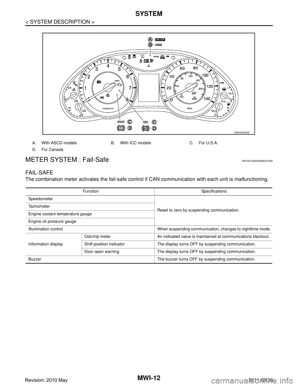
A. With ASCD models B. With ICC models C. For U.S.A.
D. For Canada
JSNIA3234ZZ
Function Specifications
Speedometer
Reset to zero by suspending communication.
Tachometer
Engine coolant temperature gauge
Engine oil pressure gauge
Illumination control When suspending communication, changes to nighttime mode.
Information display Odo/trip meter An indicated value is maintained at communications blackout.
Shift position indicator The display turns OFF by suspending communication.
Door open warning The display turns OFF by suspending communication.
Buzzer The buzzer turns OFF by suspending communication.
Revision: 2010 May2011 QX56
Page 3756 of 5598

MWI
SYSTEMMWI-13
< SYSTEM DESCRIPTION >
C
DE
F
G H
I
J
K L
M B A
O P
SPEEDOMETER
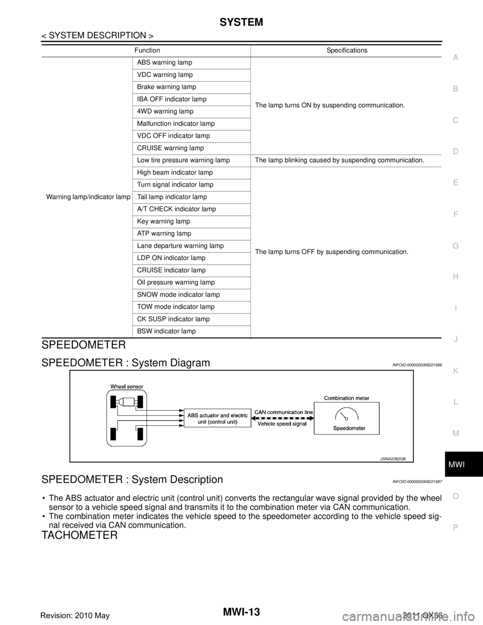
SPEEDOMETER : System DiagramINFOID:0000000006221696
SPEEDOMETER : System DescriptionINFOID:0000000006221697
The ABS actuator and electric unit (control unit) conv erts the rectangular wave signal provided by the wheel
sensor to a vehicle speed signal and transmits it to the combination meter via CAN communication.
The combination meter indicates the vehicle speed to the speedometer according to the vehicle speed sig-
nal received via CAN communication.
TACHOMETER
Warning lamp/indicator lamp ABS warning lamp
The lamp turns ON by suspending communication.
VDC warning lamp
Brake warning lamp
IBA OFF indicator lamp
4WD warning lamp
Malfunction indicator lamp
VDC OFF indicator lamp
CRUISE warning lamp
Low tire pressure warning lamp The lamp blinking caused by suspending communication.
High beam indicator lamp
The lamp turns OFF by suspending communication.
Turn signal indicator lamp
Tail lamp indicator lamp
A/T CHECK indicator lamp
Key warning lamp
AT P w a r n i n g l a m p
Lane departure warning lamp
LDP ON indicator lamp
CRUISE indicator lamp
Oil pressure warning lamp
SNOW mode indicator lamp
TOW mode indicator lamp
CK SUSP indicator lamp
BSW indicator lamp
Function Specifications
JSNIA2382GB
Revision: 2010 May2011 QX56
Page 3758 of 5598

MWI
SYSTEMMWI-15
< SYSTEM DESCRIPTION >
C
DE
F
G H
I
J
K L
M B A
O P
REFUEL CONTROL
The combination meter accelerates the fuel gauge if the all conditions listed below are met, or the ignition
switch is ON from OFF.
Ignition switch is ON position.
The vehicle is not moving.
The fuel level change by 15 (4 US gal, 3-1/4 Imp gal) or more.
ENGINE OIL PRESSURE GAUGE
ENGINE OIL PRESSURE GAUGE : System DiagramINFOID:0000000006221704
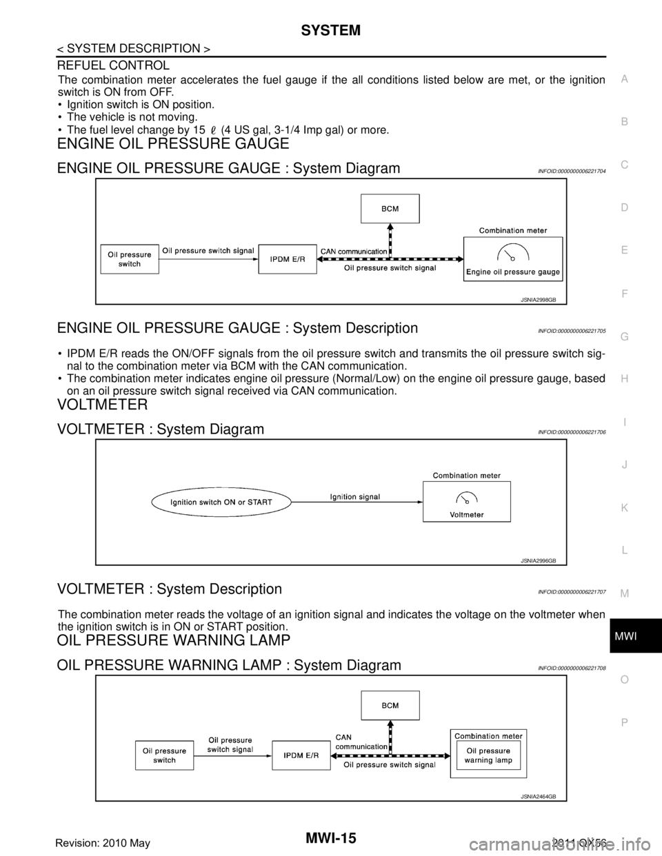
ENGINE OIL PRESSURE GAUGE : System DescriptionINFOID:0000000006221705
IPDM E/R reads the ON/OFF signals from the oil pressure switch and transmits the oil pressure switch sig-
nal to the combination meter via BCM with the CAN communication.
The combination meter indicates engine oil pressure (Normal/Low) on the engine oil pressure gauge, based
on an oil pressure switch signal received via CAN communication.
VOLTMETER
VOLTMETER : System DiagramINFOID:0000000006221706
VOLTMETER : System DescriptionINFOID:0000000006221707
The combination meter reads the voltage of an ignition signal and indicates the voltage on the voltmeter when
the ignition switch is in ON or START position.
OIL PRESSURE WARNING LAMP
OIL PRESSURE WARNING LAMP : System DiagramINFOID:0000000006221708
JSNIA2998GB
JSNIA2996GB
JSNIA2464GB
Revision: 2010 May2011 QX56