2011 INFINITI QX56 warning
[x] Cancel search: warningPage 3626 of 5598
![INFINITI QX56 2011 Factory Service Manual
LAN-206
< DTC/CIRCUIT DIAGNOSIS >[CAN SYSTEM (TYPE 4)]
A-BAG BRANCH LINE CIRCUIT
A-BAG BRANCH LINE CIRCUIT
Diagnosis ProcedureINFOID:0000000006256377
WARNING:
Before servicing, turn ignition switch INFINITI QX56 2011 Factory Service Manual
LAN-206
< DTC/CIRCUIT DIAGNOSIS >[CAN SYSTEM (TYPE 4)]
A-BAG BRANCH LINE CIRCUIT
A-BAG BRANCH LINE CIRCUIT
Diagnosis ProcedureINFOID:0000000006256377
WARNING:
Before servicing, turn ignition switch](/manual-img/42/57033/w960_57033-3625.png)
LAN-206
< DTC/CIRCUIT DIAGNOSIS >[CAN SYSTEM (TYPE 4)]
A-BAG BRANCH LINE CIRCUIT
A-BAG BRANCH LINE CIRCUIT
Diagnosis ProcedureINFOID:0000000006256377
WARNING:
Before servicing, turn ignition switch OFF, disco
nnect battery negative terminal, and wait 3 minutes
or more. (To discharge backup capacitor.)
Never use unspecified tester or other measuring device.
1.CHECK CONNECTOR
1. Turn the ignition switch OFF.
2. Disconnect the battery cable from the negative terminal.
3. Check the terminals and connectors of the air bag diagnosis sensor unit for damage, bend and loose con-
nection (unit side and connector side).
Is the inspection result normal?
YES >> GO TO 2.
NO >> Replace the main harness.
2.CHECK AIR BAG DIAGNOSIS SENSOR UNIT
Check the air bag diagnosis sensor unit. Refer to SRC-36, "
Work Flow".
Is the inspection result normal?
YES >> Replace the main harness.
NO >> Replace parts whose air bag system has a malfunction.
Revision: 2010 May2011 QX56
Page 3636 of 5598
![INFINITI QX56 2011 Factory Service Manual
LAN-216
< DTC/CIRCUIT DIAGNOSIS >[CAN SYSTEM (TYPE 4)]
TPMS BRANCH LINE CIRCUIT
TPMS BRANCH LINE CIRCUIT
Diagnosis ProcedureINFOID:0000000006256387
1.CHECK CONNECTOR
1. Turn the ignition switch OFF.
INFINITI QX56 2011 Factory Service Manual
LAN-216
< DTC/CIRCUIT DIAGNOSIS >[CAN SYSTEM (TYPE 4)]
TPMS BRANCH LINE CIRCUIT
TPMS BRANCH LINE CIRCUIT
Diagnosis ProcedureINFOID:0000000006256387
1.CHECK CONNECTOR
1. Turn the ignition switch OFF.](/manual-img/42/57033/w960_57033-3635.png)
LAN-216
< DTC/CIRCUIT DIAGNOSIS >[CAN SYSTEM (TYPE 4)]
TPMS BRANCH LINE CIRCUIT
TPMS BRANCH LINE CIRCUIT
Diagnosis ProcedureINFOID:0000000006256387
1.CHECK CONNECTOR
1. Turn the ignition switch OFF.
2. Disconnect the battery cable from the negative terminal.
3. Check the terminals and connectors of the low tire pressure warning control unit for damage, bend and loose connection (unit side and connector side).
Is the inspection result normal?
YES >> GO TO 2.
NO >> Repair the terminal and connector.
2.CHECK HARNESS FOR OPEN CIRCUIT
1. Disconnect the connector of low tire pressure warning control unit.
2. Check the resistance between the low tire pressu re warning control unit harness connector terminals.
Is the measurement value within the specification?
YES >> GO TO 3.
NO >> Repair the low tire pressure warning control unit branch line.
3.CHECK POWER SUPPLY AND GROUND CIRCUIT
Check the power supply and the ground circuit of the lo w tire pressure warning control unit. Refer to WT-51,
"Diagnosis Procedure".
Is the inspection result normal?
YES (Present error)>>Replace the low tire pressure warning control unit. Refer to WT-65, "Removal and
Installation".
YES (Past error)>>Error was detected in the low tire pressure warning control unit branch line.
NO >> Repair the power supply and the ground circuit.
Low tire pressure warning control unit harness connector Resistance (Ω)
Connector No. Terminal No.
M96 2 1 Approx. 54 – 66
Revision: 2010 May2011 QX56
Page 3660 of 5598
ENGINE OILLU-7
< PERIODIC MAINTENANCE >
C
DE
F
G H
I
J
K L
M A
LU
NP
O
PERIODIC MAINTENANCE
ENGINE OIL
InspectionINFOID:0000000006289616
OIL LEVEL
NOTE:
Before starting engine, put vehicle horizontally and check
the engine oil level. If engine is already started, stop
it and allow 10 minutes before checking.
1. Pull out oil level gauge and wipe it clean.
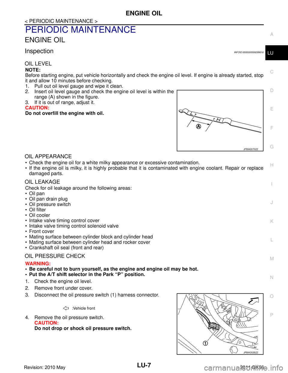
2. Insert oil level gauge and check the engine oil level is within the range (A) shown in the figure.
3. If it is out of range, adjust it.
CAUTION:
Do not overfill the engine with oil.
OIL APPEARANCE
Check the engine oil for a white milky appearance or excessive contamination.
If the engine oil is milky, it is highly probable that it is contaminated with engine coolant. Repair or replace
damaged parts.
OIL LEAKAGE
Check for oil leakage around the following areas:
Oil pan
Oil pan drain plug
Oil pressure switch
Oil filter
Oil cooler
Intake valve timing control cover
Intake valve timing control solenoid valve
Front cover
Mating surface between cylinder block and cylinder head
Mating surface between cylinder head and rocker cover
Crankshaft oil seal (front and rear)
OIL PRESSURE CHECK
WARNING:
• Be careful not to burn yourself, as th e engine and engine oil may be hot.
Put the A/T shift selector in the Park “P” position.
1. Check the engine oil level.
2. Remove front under cover.
3. Disconnect the oil pressure switch (1) harness connector.
4. Remove the oil pressure switch. CAUTION:
Do not drop or shock oil pressure switch.
JPBIA0070ZZ
:Vehicle front
JPBIA3526ZZ
Revision: 2010 May2011 QX56
Page 3661 of 5598
![INFINITI QX56 2011 Factory Service Manual
LU-8
< PERIODIC MAINTENANCE >
ENGINE OIL
5. Install the oil pressure gauge [SST: ST25051001 (J25695-1)] (A)and hose [SST: ST25052000 (J25695-2)] (B).
6. Start the engine and warm it up to normal oper INFINITI QX56 2011 Factory Service Manual
LU-8
< PERIODIC MAINTENANCE >
ENGINE OIL
5. Install the oil pressure gauge [SST: ST25051001 (J25695-1)] (A)and hose [SST: ST25052000 (J25695-2)] (B).
6. Start the engine and warm it up to normal oper](/manual-img/42/57033/w960_57033-3660.png)
LU-8
< PERIODIC MAINTENANCE >
ENGINE OIL
5. Install the oil pressure gauge [SST: ST25051001 (J25695-1)] (A)and hose [SST: ST25052000 (J25695-2)] (B).
6. Start the engine and warm it up to normal operating temperature.
7. Check the engine oil pressure with engine running under no-load. Refer to LU-17, "
EngineOilPressure".
CAUTION:
If the difference is extreme, check the oil passages and oil pump for leaks and blockages.
8. After the inspections, install oil pressure switch as follows:
a. Remove old liquid gasket adhering to oil pressure switch and engine.
b. Apply liquid gasket and tighten oil pressure switch to the specification. Use Genuine RTV Silicone Seal ant or equivalent. Refer to GI-22, "
Recommended Chemical Prod-
ucts and Sealants".
c. After warming up engine, make sure there is no leakage of engine oil with engine running.
DrainingINFOID:0000000006289617
WARNING:
Be careful not to burn yourself, as th e engine and engine oil may be hot.
Prolonged and repeated contact with used engine oil may cause skin cancer; try to avoid direct skin
contact with used oil. If skin contact is made, wash thoroughly with soap or hand cleaner as soon as
possible.
1. Warm up the engine, and check for any oil leaks.
2. Stop the engine and wait for at least 10 minutes.
3. Remove drain plug and oil filler cap to drain the old oil.
RefillingINFOID:0000000006289618
1. Install drain plug with new washer. CAUTION:
Be sure to clean drain plug and install with new washer.
2. Refill with new engine oil. Engine oil specification and viscosity:
Refer to MA-10, "
Fluids and Lubricants".
CAUTION:
The refill capacity depends on the engine oi l temperature and drain time. Use these specifica-
tions for reference only.
Always use oil level gauge to determine the proper amount of engine oil in engine.
3. Warm up the engine and check area around drain plug and oil filter for engine oil leakage.
4. Stop the engine and wait for 10 minutes.
5. Check the engine oil level. Refer to LU-7, "
Inspection".
JPBIA0074ZZ
Oil pressure switch torque : Refer to EM-57, "Exploded View".
Tightening torque : Refer to EM-54, "
Exploded View".
Engine oil capacity : Refer to LU-17, "
Periodical Maintenance Specification".
Revision: 2010 May2011 QX56
Page 3662 of 5598
OIL FILTERLU-9
< PERIODIC MAINTENANCE >
C
DE
F
G H
I
J
K L
M A
LU
NP
O
OIL FILTER
Removal and InstallationINFOID:0000000006289619
REMOVAL
1. Remove front under cover.
2. Drain engine oil. Refer to
LU-8, "
Draining".
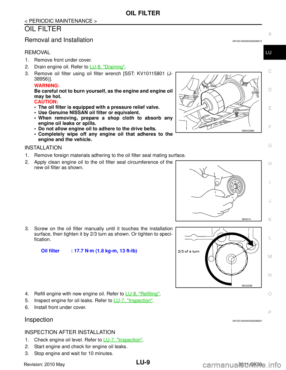
3. Remove oil filter using oil filter wrench [SST: KV10115801 (J- 38956)].
WARNING:
Be careful not to burn yourself, as the engine and engine oil
may be hot.
CAUTION:
The oil filter is equipped with a pressure relief valve.
Use Genuine NISSAN oil filter or equivalent.
When removing, prepare a s hop cloth to absorb any
engine oil leaks or spills.
Do not allow engine oil to adhere to the drive belts.
Completely wipe off any engine oil that adheres to the engine and the vehicle.
INSTALLATION
1. Remove foreign materials adhering to the oil filter seal mating surface.
2. Apply clean engine oil to the oil filter seal circumference of the
new oil filter as shown.
3. Screw on the oil filter manually until it touches the installation surface, then tighten it by 2/3 turn as shown. Or tighten to speci-
fication.
4. Refill engine with new engine oil. Refer to LU-8, "
Refilling".
5. Inspect engine for oil leaks. Refer to LU-7, "
Inspection".
6. Install front under cover.
InspectionINFOID:0000000006289620
INSPECTION AFTER INSTALLATION
1. Check engine oil level. Refer to LU-7, "Inspection".
2. Start engine and check for engine oil leaks.
3. Stop engine and wait for 10 minutes.
WBIA0388E
SMA010
Oil filter : 17.7 N·m (1.8 kg-m, 13 ft-lb)
SMA229B
Revision: 2010 May2011 QX56
Page 3664 of 5598
OIL COOLERLU-11
< REMOVAL AND INSTALLATION >
C
DE
F
G H
I
J
K L
M A
LU
NP
O
REMOVAL AND INSTALLATION
OIL COOLER
Exploded ViewINFOID:0000000006289621
Removal and InstallationINFOID:0000000006289622
WARNING:
Be careful not to burn yourself, as the en
gine oil and engine coolant may be hot.
CAUTION:
Do not spill engine coolant on the drive belt.
Do not spill engine oil on rubber parts such as drive belts and engine mounting insulator.
REMOVAL
NOTE:
When removing oil cooler only, step 1 is unnecessary.
1. Drain engine coolant from radiator and cylinder block. Refer to CO-8, "
Draining" and EM-107, "Disassem-
bly and Assembly".
NOTE:
Perform this step only when removing water pipes and hoses.
2. Remove front under cover.
3. Disconnect water hoses from oil cooler, pinching hos es near oil cooler to prevent engine coolant from
spilling.
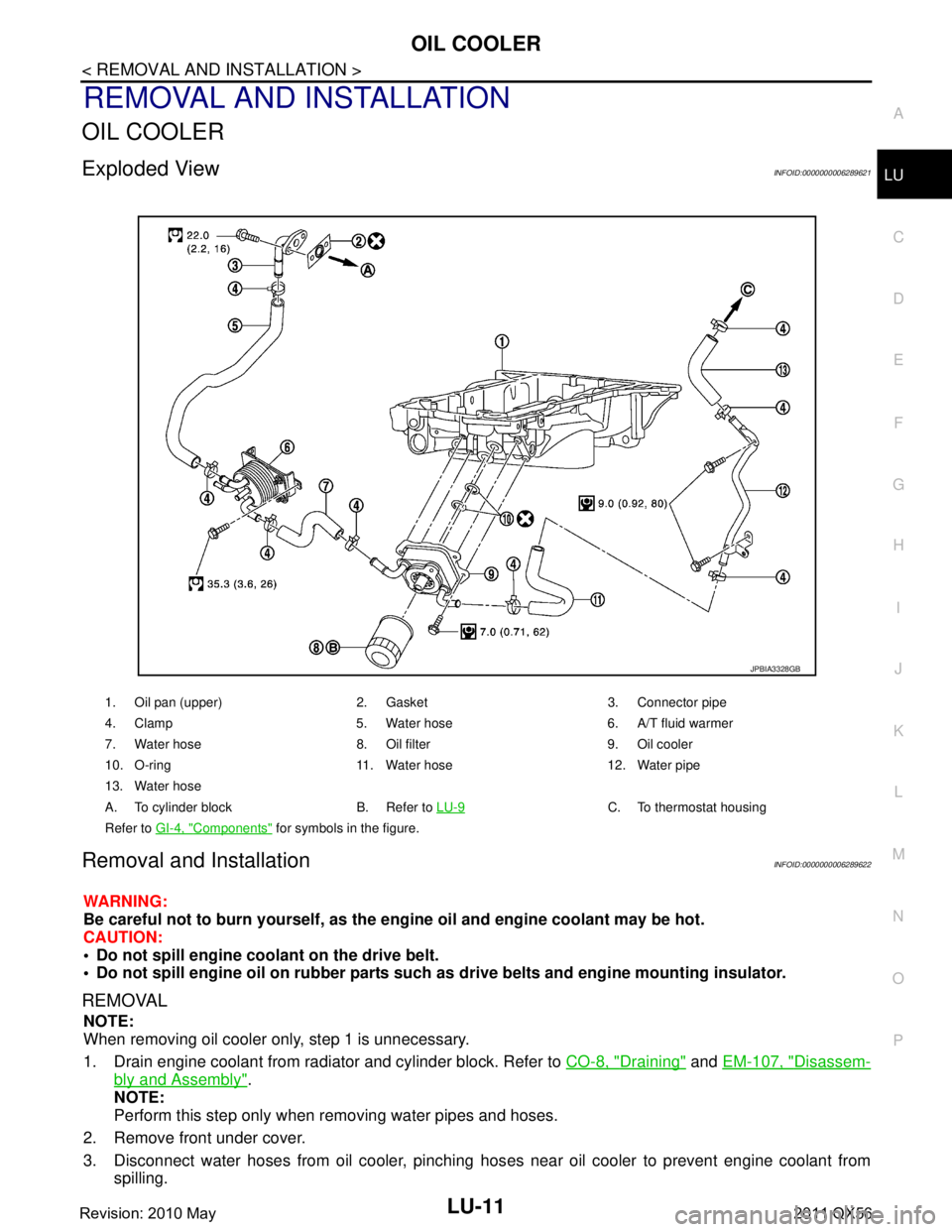
1. Oil pan (upper) 2. Gasket 3. Connector pipe
4. Clamp 5. Water hose 6. A/T fluid warmer
7. Water hose 8. Oil filter 9. Oil cooler
10. O-ring 11. Water hose 12. Water pipe
13. Water hose
A. To cylinder block B. Refer to LU-9
C. To thermostat housing
Refer to GI-4, "
Components" for symbols in the figure.
JPBIA3328GB
Revision: 2010 May2011 QX56
Page 3674 of 5598
MA-4
< PERIODIC MAINTENANCE >
GENERAL MAINTENANCE
PERIODIC MAINTENANCE
GENERAL MAINTENANCE
Explanation of General MaintenanceINFOID:0000000006287728
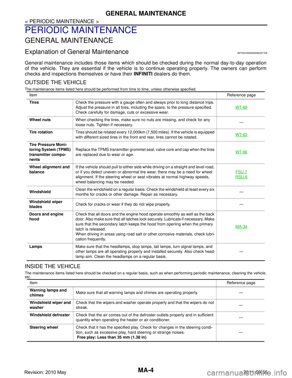
General maintenance includes those items which shoul d be checked during the normal day-to-day operation
of the vehicle. They are essential if the vehicle is to continue operating properly. The owners can perform
checks and inspections themselves or have their INFINITI dealers do them.
OUTSIDE THE VEHICLE
The maintenance items listed here should be performed fr om time to time, unless otherwise specified.
INSIDE THE VEHICLE
The maintenance items listed here should be checked on a regular basis, such as when performing periodic maintenance, cleaning the vehicle,
etc.
Item Reference page
Tires Check the pressure with a gauge often and always prior to long distance trips.
Adjust the pressure in all tires, including the spare, to the pressure specified.
Check carefully for damage, cuts or excessive wear. WT-69
Wheel nuts
When checking the tires, make sure no nuts are missing, and check for any
loose nuts. Tighten if necessary. —
Tire rotation Tires should be rotated every 12,000km (7,500 miles). If the vehicle is equipped
with different sized tires in the front and rear, tires cannot be rotated. WT-63
Tire Pressure Moni-
toring System (TPMS)
transmitter compo-
nentsReplace the TPMS transmitter grommet seal, valve core and cap when the tires
are replaced due to wear or age.
WT-66
Wheel alignment and
balanceIf the vehicle should pull to either side while driving on a straight and level road,
or if you detect uneven or abnormal tire wear, there may be a need for wheel
alignment. If the steering wheel or seat vibrates at normal highway speeds,
wheel balancing may be needed. FSU-7
RSU-6
Windshield
Clean the windshield on a regular basis. Check the windshield at least every six
months for cracks or other damage. Repair as necessary. —
Windshield wiper
blades Check for cracks or wear if they do not wipe properly. —
Doors and engine
hood Check that all doors and the engine hood operate smoothly as well as the back
door. Also make sure that all latches lock securely. Lubricate if necessary. Make
sure that the secondary latch keeps the hood from opening when the primary
latch is released.
When driving in areas using road salt or other corrosive materials, check lubri-
cation frequently. MA-34
Lamps
Make sure that the headlamps, stop lamps, tail lamps, turn signal lamps, and
other lamps are all operating properly and installed securely. Also check head-
lamp aim. Clean the headlamps on a regular basis. —
Item
Reference page
Warning lamps and
chimes Make sure that all warning lamps and chimes are operating properly. —
Windshield wiper and
washer Check that the wipers and washer operate properly and that the wipers do not
streak.
—
Windshield defroster Check that the air comes out of the defroster outlets properly and in sufficient
quantity when operating the heater or air conditioner. —
Steering wheel Check that it has the specified play. Check for changes in the steering condi-
tion, such as excessive play, hard steering or strange noises.
Free play: Less than 35 mm (1.38 in) —
Revision: 2010 May2011 QX56
Page 3682 of 5598
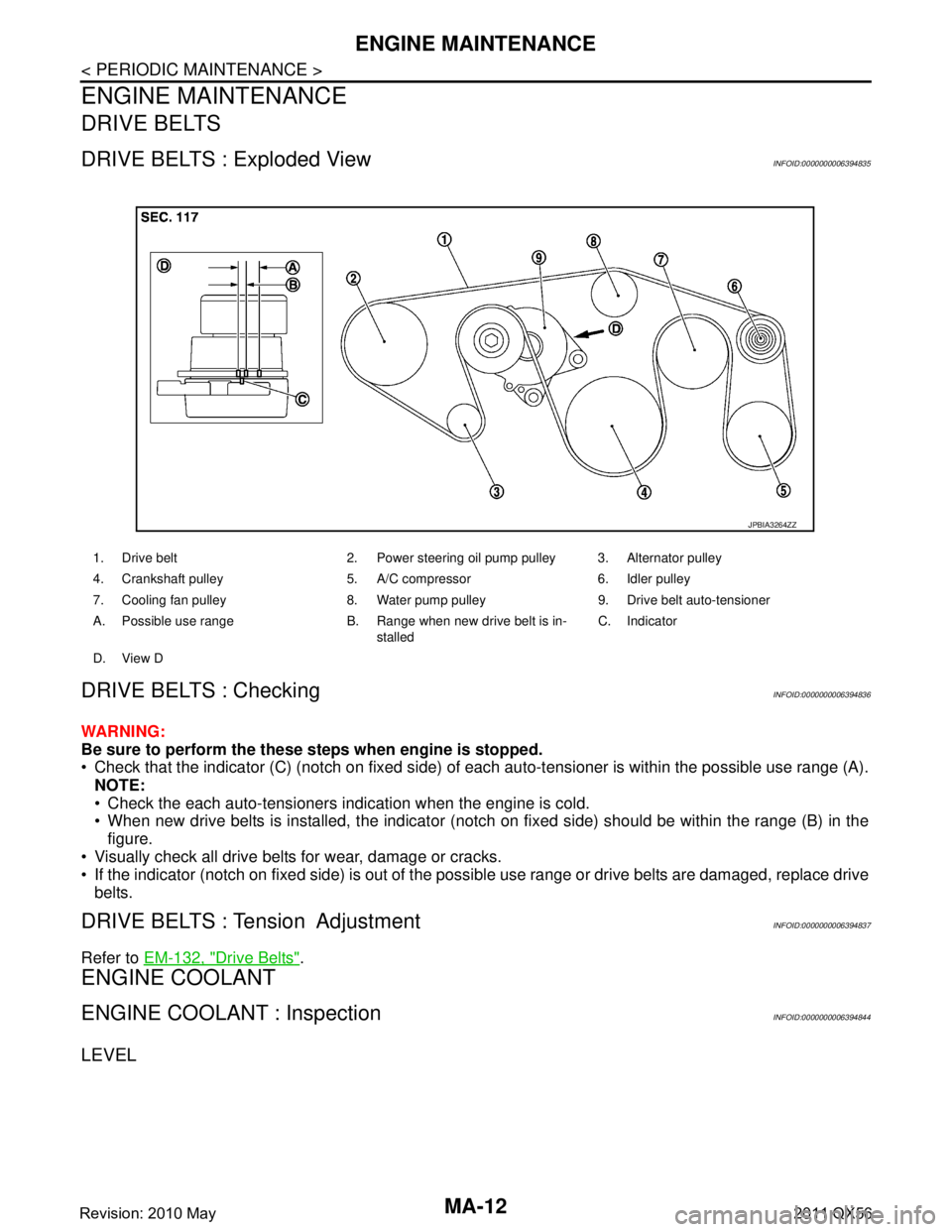
MA-12
< PERIODIC MAINTENANCE >
ENGINE MAINTENANCE
ENGINE MAINTENANCE
DRIVE BELTS
DRIVE BELTS : Exploded ViewINFOID:0000000006394835
DRIVE BELTS : CheckingINFOID:0000000006394836
WARNING:
Be sure to perform the these steps when engine is stopped.
Check that the indicator (C) (notch on fixed side) of each auto-tensioner is within the possible use range (A).
NOTE:
Check the each auto-tensioners indication when the engine is cold.
When new drive belts is installed, the indicator (notch on fixed side) should be within the range (B) in the\
figure.
Visually check all drive belts for wear, damage or cracks.
If the indicator (notch on fixed side) is out of the possible use range or drive belts are damaged, replace drive
belts.
DRIVE BELTS : Tension AdjustmentINFOID:0000000006394837
Refer to EM-132, "Drive Belts".
ENGINE COOLANT
ENGINE COOLANT : InspectionINFOID:0000000006394844
LEVEL
1. Drive belt 2. Power steering oil pump pulley 3. Alternator pulley
4. Crankshaft pulley 5. A/C compressor 6. Idler pulley
7. Cooling fan pulley 8. Water pump pulley 9. Drive belt auto-tensioner
A. Possible use range B. Range when new drive belt is in-
stalledC. Indicator
D. View D
JPBIA3264ZZ
Revision: 2010 May2011 QX56