Page 3783 of 5598
MWI-40
< ECU DIAGNOSIS INFORMATION >
COMBINATION METER
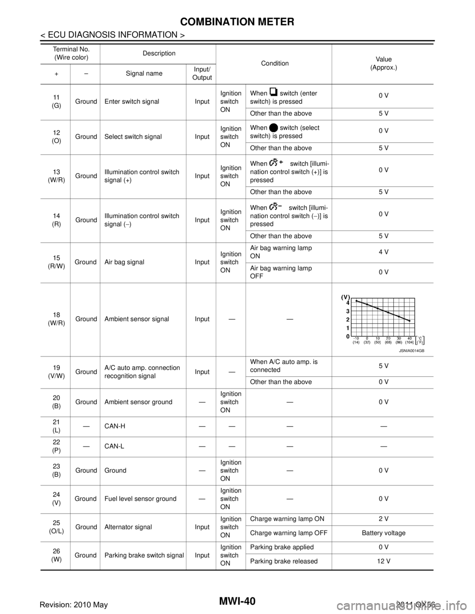
11
(G) Ground Enter switch signal Input Ignition
switch
ONWhen switch (enter
switch) is pressed
0 V
Other than the above 5 V
12
(O) Ground Select switch signal Input Ignition
switch
ONWhen switch (select
switch) is pressed
0 V
Other than the above 5 V
13
(W/R) Ground
Illumination control switch
signal (+) InputIgnition
switch
ON When switch [illumi-
nation control sw
itch (+)] is
pressed 0 V
Other than the above 5 V
14
(R) Ground Illumination control switch
signal (
−) InputIgnition
switch
ON When switch [illumi-
nation control switch (
−)] is
pressed 0 V
Other than the above 5 V
15
(R/W) Ground Air bag signal Input Ignition
switch
ONAir bag warning lamp
ON
4 V
Air bag warning lamp
OFF 0 V
18
(W/R) Ground Ambient sensor signal Input — —
19
(V/W) Ground A/C auto amp. connection
recognition signal Input —When A/C auto amp. is
connected
5 V
Other than the above 0 V
20
(B) Ground Ambient sensor ground — Ignition
switch
ON—0 V
21
(L) —CAN-H — — — —
22
(P) —CAN-L — — — —
23
(B) Ground Ground — Ignition
switch
ON
—0 V
24
(V) Ground Fuel level sensor ground — Ignition
switch
ON—0 V
25
(O/L) Ground Alternator signal Input Ignition
switch
ONCharge warning lamp ON 2 V
Charge warning lamp OFF Battery voltage
26
(W) Ground Parking brake switch signal Input Ignition
switch
ONParking brake applied 0 V
Parking brake released 12 V
Te r m i n a l N o .
(Wire color) Description
ConditionVa l u e
(Approx.)
+ – Signal name Input/
Output
JSNIA0014GB
Revision: 2010 May2011 QX56
Page 3785 of 5598

MWI-42
< ECU DIAGNOSIS INFORMATION >
COMBINATION METER
Fail-Safe
INFOID:0000000006221722
FA I L - S A F E
The combination meter activates the fail-safe contro l if CAN communication with each unit is malfunctioning.
37
(R/Y) Ground Non-manual mode signal Input Ignition
switch
ONSelector manual mode po-
sition
12 V
Other than the above 0 V
38
(L/W) Ground Manual mode shift down
signal InputIgnition
switch
ON Selector lever DOWN oper-
ation
0 V
Other than the above 12 V
39
(Y/B) Ground Manual mode shift up sig-
nal InputIgnition
switch
ON Selector lever UP operation 0 V
Other than the above 12 V
40
(G/W) Ground Manual mode signal Input Ignition
switch
ONSelector manual mode po-
sition
0 V
Other than the above 12 V
Te r m i n a l N o .
(Wire color) Description
ConditionVa l u e
(Approx.)
+ – Signal name Input/
Output
Function Specifications
Speedometer
Reset to zero by suspending communication.
Tachometer
Engine coolant temperature gauge
Engine oil pressure gauge
Illumination control When suspending communication, changes to nighttime mode.
Information display Odo/trip meter An indicated value is maintained at communications blackout.
Shift position indicator The display turns OFF by suspending communication.
Door open warning The display turns OFF by suspending communication.
Buzzer The buzzer turns OFF by suspending communication.
Revision: 2010 May2011 QX56
Page 3786 of 5598

MWI
COMBINATION METERMWI-43
< ECU DIAGNOSIS INFORMATION >
C
DE
F
G H
I
J
K L
M B A
O P
DTC IndexINFOID:0000000006221723
Warning lamp/indicator lamp ABS warning lamp
The lamp turns ON by suspending communication.
VDC warning lamp
Brake warning lamp
IBA OFF indicator lamp
4WD warning lamp
Malfunction indicator lamp
VDC OFF indicator lamp
CRUISE warning lamp
Low tire pressure warning lamp The lamp blinking caused by suspending communication.
High beam indicator lamp
The lamp turns OFF by suspending communication.
Turn signal indicator lamp
Tail lamp indicator lamp
A/T CHECK indicator lamp
Key warning lamp
AT P w a r n i n g l a m p
Lane departure warning lamp
LDP ON indicator lamp
CRUISE indicator lamp
Oil pressure warning lamp
SNOW mode indicator lamp
TOW mode indicator lamp
CK SUSP indicator lamp
BSW indicator lamp
Function Specifications
Display contents of CONSULT-III Diagnostic item is detected when... Refer to
CAN COMM CIRCUIT
[U1000] When combination meter is not transmitting or receiving CAN communication signal
for 2 seconds or more. MWI-59,
"Diagnosis
Procedure"
CONTROL UNIT (CAN)
[U1010]
When detecting error during the initial diagnosis of the CAN controller of combina-
tion meter. MWI-60, "Diagnosis
Procedure"
VEHICLE SPEED
[B2205]
The abnormal vehicle speed signal is input from the ABS actuator and electric unit
(control unit) for
2 seconds or more. MWI-61, "Diagnosis
Procedure"
ENGINE SPEED
[B2267]
If ECM continuously transmits abnormal engine speed signals for 2 seconds or
more. MWI-62, "Diagnosis
Procedure"
WATER TEMP
[B2268]
If ECM continuously transmits abnormal engine coolant temperature signals for 60
seconds or more. MWI-63, "Diagnosis
Procedure"
Revision: 2010 May2011 QX56
Page 3821 of 5598
MWI-78
< SYMPTOM DIAGNOSIS >
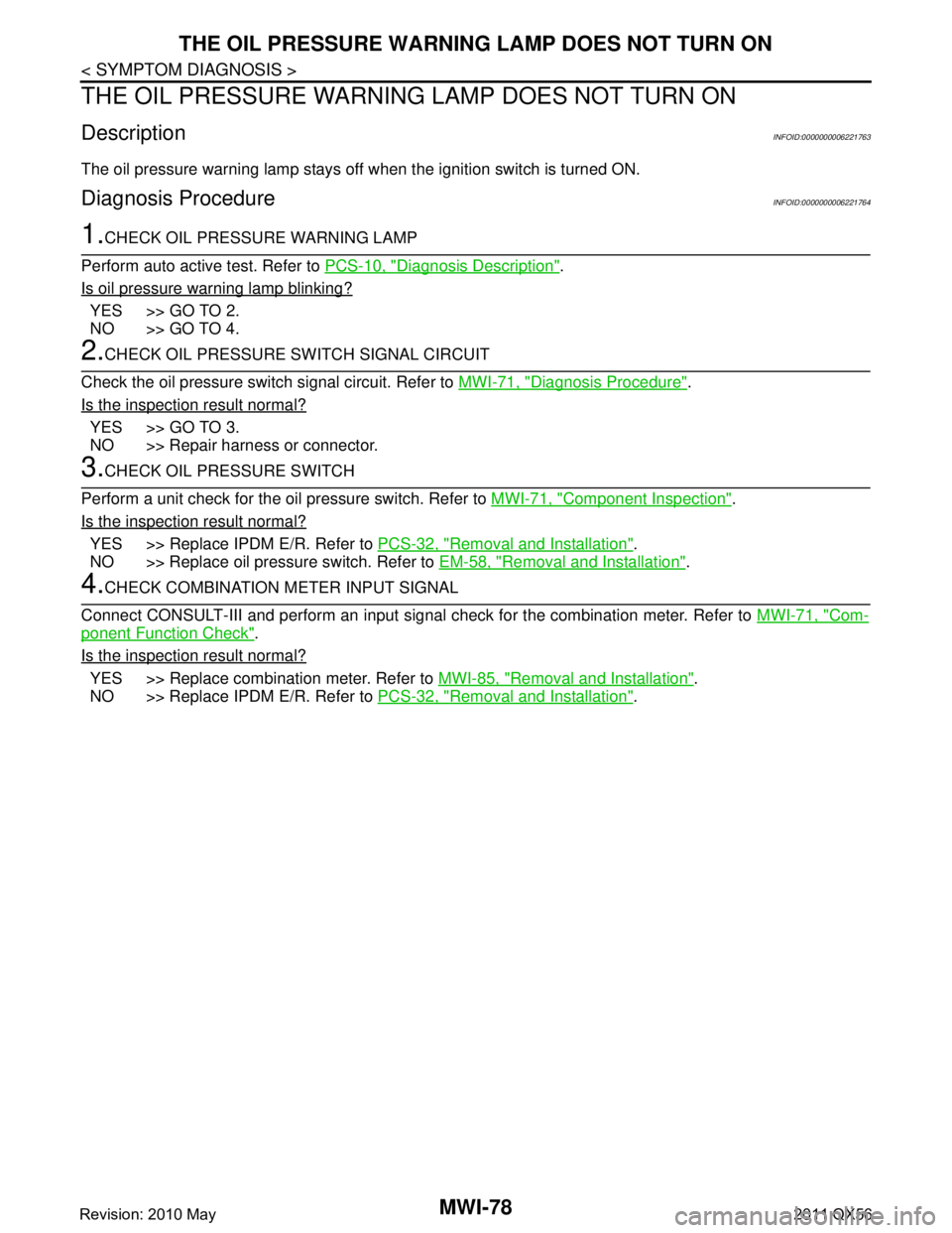
THE OIL PRESSURE WARNING LAMP DOES NOT TURN ON
THE OIL PRESSURE WARNING LAMP DOES NOT TURN ON
DescriptionINFOID:0000000006221763
The oil pressure warning lamp stays off when the ignition switch is turned ON.
Diagnosis ProcedureINFOID:0000000006221764
1.CHECK OIL PRESSURE WARNING LAMP
Perform auto active test. Refer to PCS-10, "
Diagnosis Description".
Is oil pressure warning lamp blinking?
YES >> GO TO 2.
NO >> GO TO 4.
2.CHECK OIL PRESSURE SWITCH SIGNAL CIRCUIT
Check the oil pressure switch signal circuit. Refer to MWI-71, "
Diagnosis Procedure".
Is the inspection result normal?
YES >> GO TO 3.
NO >> Repair harness or connector.
3.CHECK OIL PRESSURE SWITCH
Perform a unit check for the oil pressure switch. Refer to MWI-71, "
Component Inspection".
Is the inspection result normal?
YES >> Replace IPDM E/R. Refer to PCS-32, "Removal and Installation".
NO >> Replace oil pressure switch. Refer to EM-58, "
Removal and Installation".
4.CHECK COMBINATION METER INPUT SIGNAL
Connect CONSULT-III and perform an input signal check for the combination meter. Refer to MWI-71, "
Com-
ponent Function Check".
Is the inspection result normal?
YES >> Replace combination meter. Refer to MWI-85, "Removal and Installation".
NO >> Replace IPDM E/R. Refer to PCS-32, "
Removal and Installation".
Revision: 2010 May2011 QX56
Page 3822 of 5598
MWI
THE OIL PRESSURE WARNING LAMP DOES NOT TURN OFFMWI-79
< SYMPTOM DIAGNOSIS >
C
DE
F
G H
I
J
K L
M B A
O P
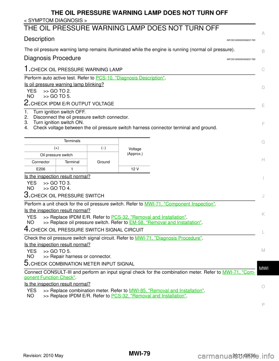
THE OIL PRESSURE WARNING LAMP DOES NOT TURN OFF
DescriptionINFOID:0000000006221765
The oil pressure warning lamp remains illuminated while the engine is running (normal oil pressure).
Diagnosis ProcedureINFOID:0000000006221766
1.CHECK OIL PRESSURE WARNING LAMP
Perform auto active test. Refer to PCS-10, "
Diagnosis Description".
Is oil pressure warning lamp blinking?
YES >> GO TO 2.
NO >> GO TO 5.
2.CHECK IPDM E/R OUTPUT VOLTAGE
1. Turn ignition switch OFF.
2. Disconnect the oil pressure switch connector.
3. Turn ignition switch ON.
4. Check voltage between the oil pressure switch harness connector terminal and ground.
Is the inspection result normal?
YES >> GO TO 3.
NO >> GO TO 4.
3.CHECK OIL PRESSURE SWITCH
Perform a unit check for the oil pressure switch. Refer to MWI-71, "
Component Inspection".
Is the inspection result normal?
YES >> Replace IPDM E/R. Refer to PCS-32, "Removal and Installation".
NO >> Replace oil pressure switch. Refer to EM-58, "
Removal and Installation".
4.CHECK OIL PRESSURE SWITCH SIGNAL CIRCUIT
Check the oil pressure switch signal circuit. Refer to MWI-71, "
Diagnosis Procedure".
Is the inspection result normal?
YES >> GO TO 5.
NO >> Repair harness or connector.
5.CHECK COMBINATION METER INPUT SIGNAL
Connect CONSULT-III and perform an input signal check for the combination meter. Refer to MWI-71, "
Com-
ponent Function Check".
Is the inspection result normal?
YES >> Replace combination meter. Refer to MWI-85, "Removal and Installation".
NO >> Replace IPDM E/R. Refer to PCS-32, "
Removal and Installation".
Te r m i n a l s
Voltag e
(Approx.)
(+) (
−)
Oil pressure switch Ground
Connector Terminal
E206 1 12 V
Revision: 2010 May2011 QX56
Page 3823 of 5598
MWI-80
< SYMPTOM DIAGNOSIS >
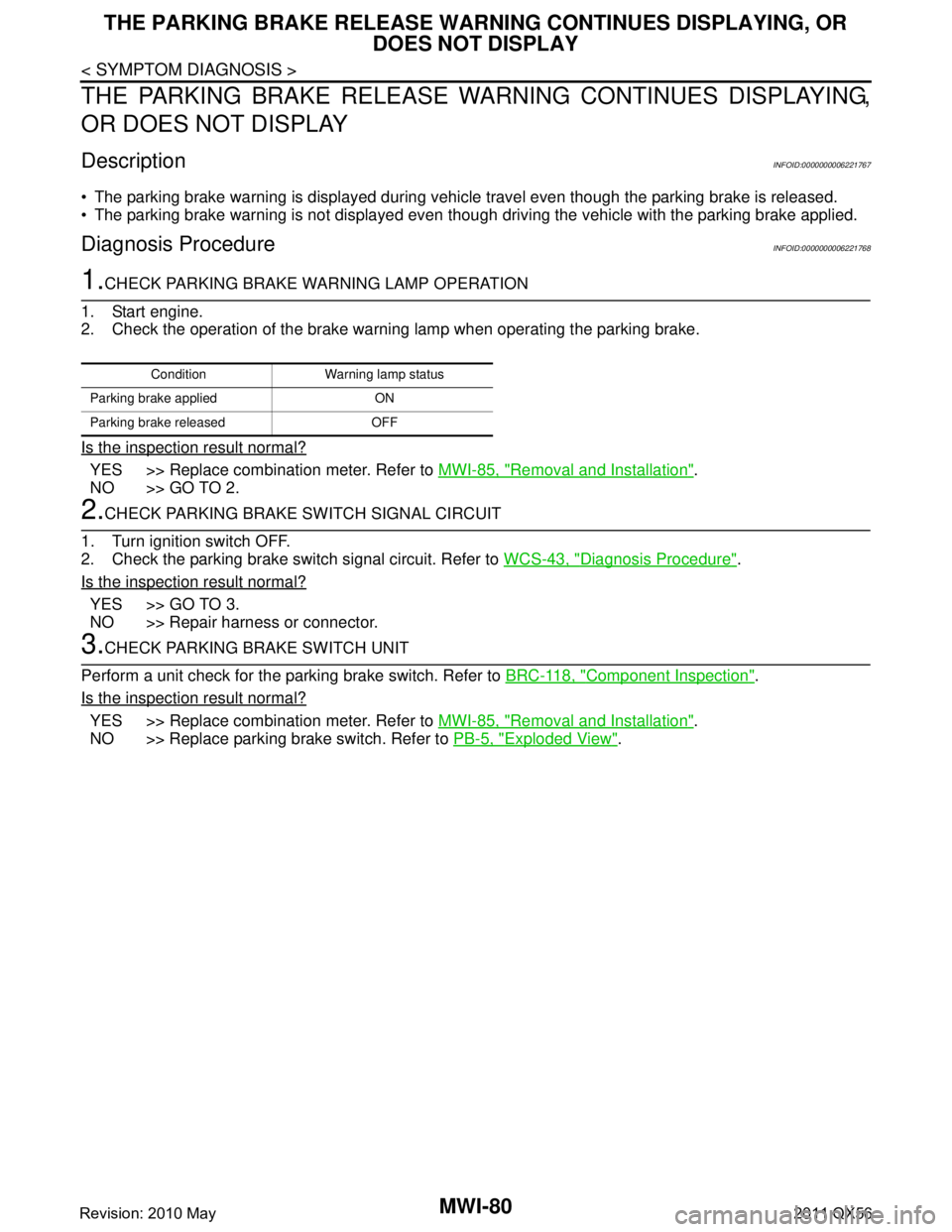
THE PARKING BRAKE RELEASE WARNING CONTINUES DISPLAYING, OR
DOES NOT DISPLAY
THE PARKING BRAKE RELEASE WA RNING CONTINUES DISPLAYING,
OR DOES NOT DISPLAY
DescriptionINFOID:0000000006221767
The parking brake warning is displayed during vehi cle travel even though the parking brake is released.
The parking brake warning is not displayed even though driving the vehicle with the parking brake applied.
Diagnosis ProcedureINFOID:0000000006221768
1.CHECK PARKING BRAKE WARNING LAMP OPERATION
1. Start engine.
2. Check the operation of the brake warni ng lamp when operating the parking brake.
Is the inspection result normal?
YES >> Replace combination meter. Refer to MWI-85, "Removal and Installation".
NO >> GO TO 2.
2.CHECK PARKING BRAKE SWITCH SIGNAL CIRCUIT
1. Turn ignition switch OFF.
2. Check the parking brake switch signal circuit. Refer to WCS-43, "
Diagnosis Procedure".
Is the inspection result normal?
YES >> GO TO 3.
NO >> Repair harness or connector.
3.CHECK PARKING BRAKE SWITCH UNIT
Perform a unit check for the parking brake switch. Refer to BRC-118, "
Component Inspection".
Is the inspection result normal?
YES >> Replace combination meter. Refer to MWI-85, "Removal and Installation".
NO >> Replace parking brake switch. Refer to PB-5, "
Exploded View".
Condition Warning lamp status
Parking brake applied ON
Parking brake released OFF
Revision: 2010 May2011 QX56
Page 3824 of 5598
MWI
THE LOW WASHER FLUID WARNING CONTINUES DISPLAYING, OR DOES
NOT DISPLAY
MWI-81
< SYMPTOM DIAGNOSIS >
C
DE
F
G H
I
J
K L
M B A
O P
THE LOW WASHER FLUID WARNING CONTINUES DISPLAYING, OR
DOES NOT DISPLAY
DescriptionINFOID:0000000006221769
The warning is still displayed even after washer fluid is added.
The warning is not displayed even though the washer tank is empty.
Diagnosis ProcedureINFOID:0000000006221770
1.CHECK WASHER LEVEL SWITCH SIGNAL CIRCUIT
Check the washer level switch signal circuit. Refer to MWI-73, "
Diagnosis Procedure".
Is the inspection result normal?
YES >> GO TO 2.
NO >> Repair harness or connector.
2.CHECK WASHER LEVEL SWITCH UNIT
Perform a unit check for the washer level switch. Refer to MWI-73, "
Component Inspection".
Is the inspection result normal?
YES >> Replace combination meter. Refer to MWI-85, "Removal and Installation".
NO >> Replace washer level switch. Refer to WW-62, "
Removal and Installation".
Revision: 2010 May2011 QX56
Page 3825 of 5598
MWI-82
< SYMPTOM DIAGNOSIS >
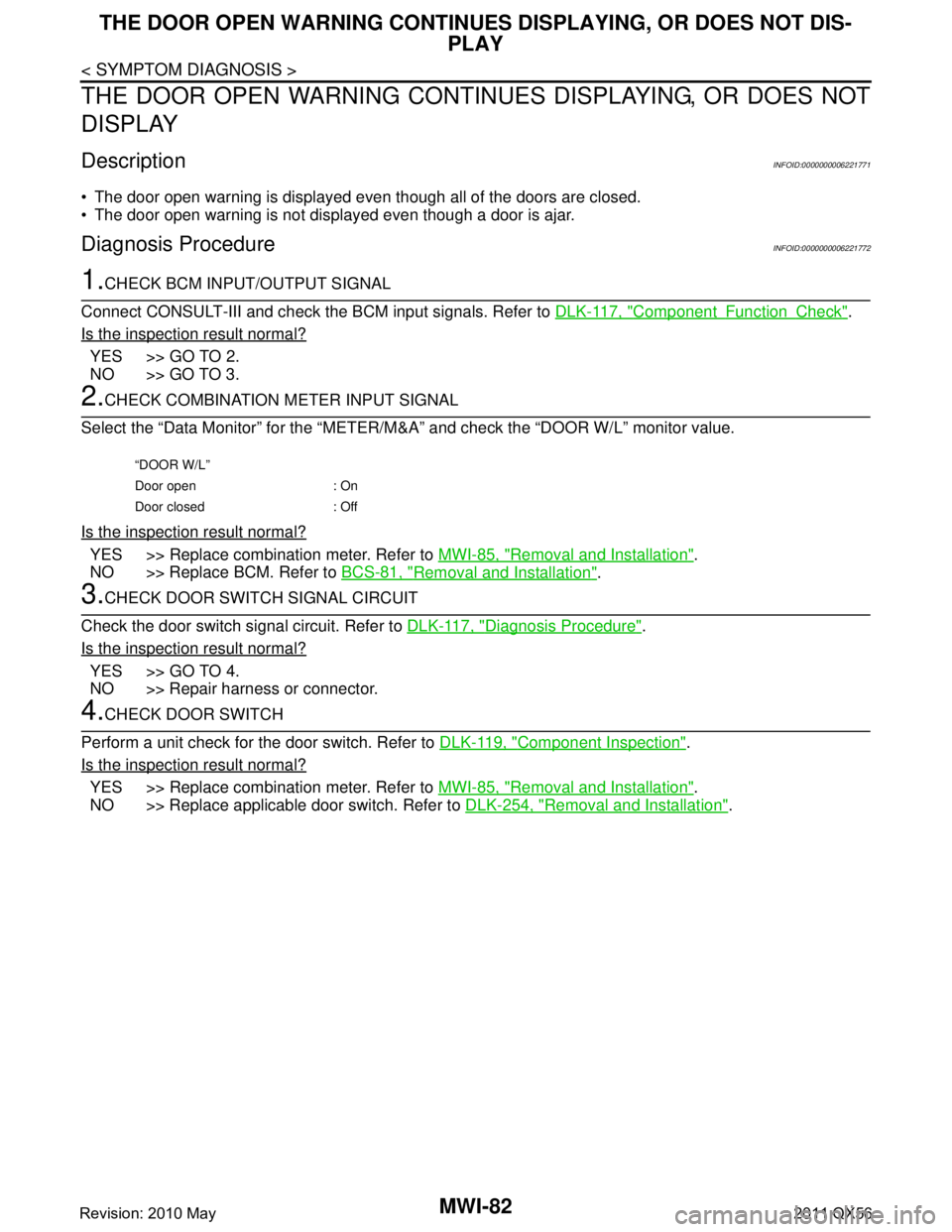
THE DOOR OPEN WARNING CONTINUES DISPLAYING, OR DOES NOT DIS-
PLAY
THE DOOR OPEN WARNING CONTIN UES DISPLAYING, OR DOES NOT
DISPLAY
DescriptionINFOID:0000000006221771
The door open warning is displayed even though all of the doors are closed.
The door open warning is not displayed even though a door is ajar.
Diagnosis ProcedureINFOID:0000000006221772
1.CHECK BCM INPUT/OUTPUT SIGNAL
Connect CONSULT-III and check the BCM input signals. Refer to DLK-117, "
ComponentFunctionCheck".
Is the inspection result normal?
YES >> GO TO 2.
NO >> GO TO 3.
2.CHECK COMBINATION METER INPUT SIGNAL
Select the “Data Monitor” for the “METER/M&A” and check the “DOOR W/L” monitor value.
Is the inspection result normal?
YES >> Replace combination meter. Refer to MWI-85, "Removal and Installation".
NO >> Replace BCM. Refer to BCS-81, "
Removal and Installation".
3.CHECK DOOR SWITCH SIGNAL CIRCUIT
Check the door switch signal circuit. Refer to DLK-117, "
Diagnosis Procedure".
Is the inspection result normal?
YES >> GO TO 4.
NO >> Repair harness or connector.
4.CHECK DOOR SWITCH
Perform a unit check for the door switch. Refer to DLK-119, "
Component Inspection".
Is the inspection result normal?
YES >> Replace combination meter. Refer to MWI-85, "Removal and Installation".
NO >> Replace applicable door switch. Refer to DLK-254, "
Removal and Installation".
“DOOR W/L”
Door open : On
Door closed : Off
Revision: 2010 May2011 QX56