Page 3234 of 5598
![INFINITI QX56 2011 Factory Service Manual
HAC-128
< DTC/CIRCUIT DIAGNOSIS >[AUTOMATIC AIR CONDITIONING]
REAR A/C SOLENOID VALVE
REAR A/C SOLENOID VALVE
Diagnosis ProcedureINFOID:0000000006275976
1.CHECK FUSE
1. Turn ignition switch OFF.
2. C INFINITI QX56 2011 Factory Service Manual
HAC-128
< DTC/CIRCUIT DIAGNOSIS >[AUTOMATIC AIR CONDITIONING]
REAR A/C SOLENOID VALVE
REAR A/C SOLENOID VALVE
Diagnosis ProcedureINFOID:0000000006275976
1.CHECK FUSE
1. Turn ignition switch OFF.
2. C](/manual-img/42/57033/w960_57033-3233.png)
HAC-128
< DTC/CIRCUIT DIAGNOSIS >[AUTOMATIC AIR CONDITIONING]
REAR A/C SOLENOID VALVE
REAR A/C SOLENOID VALVE
Diagnosis ProcedureINFOID:0000000006275976
1.CHECK FUSE
1. Turn ignition switch OFF.
2. Check 10A fuse [No.4, located in fuse block (J/B)]. NOTE:
Refer to PG-140, "
Fuse, Connector and Terminal Arrangement".
Is the inspection result normal?
YES >> GO TO 2.
NO >> Replace the blown fuse after repairing the affected circuit if a fuse is blown.
2.CHECK REAR A/C SOLENOID VALVE POWER SUPPLY
1. Disconnect rear A/C solenoid valve connector.
2. Turn ignition switch ON and front air conditioning system ON.
3. Check voltage between rear A/C solenoid valve harness connector and ground when rear blower motor is operated.
Is the inspection result normal?
YES >> GO TO 3.
NO >> GO TO 4.
3.CHECK REAR A/C SOLENOID VALVE GROUND CIRCUIT
1. Turn ignition switch OFF.
2. Check continuity between rear A/C solenoid valve harness connector and ground.
Is the inspection result normal?
YES >> Replace rear expansion valve assembly. Refer to HA-49, "EXPANSION VALVE : Removal and
Installation".
NO >> Repair harness or connector.
4.CHECK REAR A/C RELAY POWER SUPPLY
1. Turn ignition switch OFF.
2. Disconnect rear A/C relay connector.
3. Turn ignition switch ON.
4. Check voltage between rear A/C relay harness connector and ground.
Is the inspection result normal?
YES >> GO TO 5.
+
−Condition Vo l ta g e
(Approx.)
Rear A/C solenoid valve
Connector Terminal
B207 1 Ground Rear blower motor ON Battery voltage
OFF 0 V
Rear A/C sole noid valve
—Continuity
Connector Terminal
B207 2 Ground Existed
+ −Vol tag e
(Approx.)
Rear A/C relay
Connector Terminal
E87 1
Ground Battery voltage
3
Revision: 2010 May2011 QX56
Page 3235 of 5598
![INFINITI QX56 2011 Factory Service Manual
REAR A/C SOLENOID VALVEHAC-129
< DTC/CIRCUIT DIAGNOSIS > [AUTOMATIC AIR CONDITIONING]
C
D
E
F
G H
J
K L
M A
B
HAC
N
O P
NO >> Repair harness or connector between rear A/C relay and fuse block (J/B).
INFINITI QX56 2011 Factory Service Manual
REAR A/C SOLENOID VALVEHAC-129
< DTC/CIRCUIT DIAGNOSIS > [AUTOMATIC AIR CONDITIONING]
C
D
E
F
G H
J
K L
M A
B
HAC
N
O P
NO >> Repair harness or connector between rear A/C relay and fuse block (J/B).](/manual-img/42/57033/w960_57033-3234.png)
REAR A/C SOLENOID VALVEHAC-129
< DTC/CIRCUIT DIAGNOSIS > [AUTOMATIC AIR CONDITIONING]
C
D
E
F
G H
J
K L
M A
B
HAC
N
O P
NO >> Repair harness or connector between rear A/C relay and fuse block (J/B).
5.CHECK REAR A/C RERAY CONTROL CIRCUIT FOR OPEN
1. Turn ignition switch OFF.
2. Disconnect A/C auto amp. connector.
3. Check continuity between rear A/C relay har ness connector and A/C auto amp. harness connector.
Is the inspection result normal?
YES >> GO TO 6.
NO >> Repair harness or connector.
6.CHECK REAR A/C RELAY CONTROL CIRCUIT FOR SHORT
Check continuity between rear A/C relay harness connector and ground.
Is the inspection result normal?
YES >> GO TO 7.
NO >> Repair harness or connector.
7.CHECK REAR A/C SOLENOID VALVE POWER SUPPLY CIRCUIT
Check continuity between rear A/C relay harness c onnector and rear A/C solenoid valve harness connector.
Is the inspection result normal?
YES >> GO TO 8.
NO >> Repair harness or connector.
8.CHECK REAR A/C RELAY
Check rear A/C relay. Refer to HAC-129, "
Component Inspection".
Is the inspection result normal?
YES >> Replace A/C auto amp.. Refer to HAC-146, "Removal and Installation".
NO >> Replace rear A/C relay.
Component InspectionINFOID:0000000006275977
1.CHECK REAR A/C RELAY
1. Remove rear A/C relay.
Rear A/C relay A/C auto amp. Continuity
Connector Terminal Connector Terminal
E87 2 M50 38 Existed
Rear A/C relay —Continuity
Connector Terminal
E87 2 Ground Not existed
Rear A/C relay Rear A/C solenoid valve Continuity
Connector Terminal Connector Terminal
E87 5 B207 1 Existed
Revision: 2010 May2011 QX56
Page 3237 of 5598
![INFINITI QX56 2011 Factory Service Manual
REAR BLOWER MOTORHAC-131
< DTC/CIRCUIT DIAGNOSIS > [AUTOMATIC AIR CONDITIONING]
C
D
E
F
G H
J
K L
M A
B
HAC
N
O P
REAR BLOWER MOTOR
Diagnosis ProcedureINFOID:0000000006275978
1.CHECK FUSE
1. Turn ign INFINITI QX56 2011 Factory Service Manual
REAR BLOWER MOTORHAC-131
< DTC/CIRCUIT DIAGNOSIS > [AUTOMATIC AIR CONDITIONING]
C
D
E
F
G H
J
K L
M A
B
HAC
N
O P
REAR BLOWER MOTOR
Diagnosis ProcedureINFOID:0000000006275978
1.CHECK FUSE
1. Turn ign](/manual-img/42/57033/w960_57033-3236.png)
REAR BLOWER MOTORHAC-131
< DTC/CIRCUIT DIAGNOSIS > [AUTOMATIC AIR CONDITIONING]
C
D
E
F
G H
J
K L
M A
B
HAC
N
O P
REAR BLOWER MOTOR
Diagnosis ProcedureINFOID:0000000006275978
1.CHECK FUSE
1. Turn ignition switch OFF.
2. Check 20A fuse [No. 16, located in fuse block (J/B)]. NOTE:
Refer to PG-140, "
Fuse, Connector and Terminal Arrangement".
Is the inspection result normal?
YES >> GO TO 2.
NO >> Replace the blown fuse after repairing the affected circuit if a fuse is blown.
2.CHECK REAR BLOWER MOTOR POWER SUPPLY
1. Turn ignition switch OFF.
2. Disconnect rear blower motor connector.
3. Turn ignition switch ON.
4. Check voltage between rear blower motor harness connector and ground.
Is the inspection result normal?
YES >> GO TO 3.
NO >> Repair harness or connector between rear blower motor and fuse block (J/B).
3.CHECK REAR BLOWER MOTOR GROUND CIRCUIT
1. Turn ignition switch OFF.
2. Check continuity between rear blower motor harness connector and ground.
Is the inspection result normal?
YES >> GO TO 4.
NO >> Repair harness or connector.
4.CHECK REAR BLOWER MOTOR CONTROL SIGNAL CIRCUIT
1. Disconnect A/C auto amp. connector.
2. Check continuity between rear blower motor harness connector and A/C auto amp. harness connector.
Is the inspection result normal?
YES >> GO TO 5.
NO >> Repair harness or connector.
5.CHECK REAR BLOWER MOTOR CONTROL SIGNAL
1. Reconnect rear blower motor connector and A/C auto amp. connector.
2. Turn ignition switch ON.
3. Operate MODE switch to set air outlet to VENT.
+
−Vol tag e
Rear blower motor
Connector Terminal M302 1 Ground Battery voltage
Rear blower motor —Continuity
Connector Terminal
M302 3 Ground Existed
Rear blower motor A/C auto amp. Continuity
Connector Terminal Connector Terminal
M302 2 M50 34 Existed
Revision: 2010 May2011 QX56
Page 3335 of 5598
INL-68
< REMOVAL AND INSTALLATION >
MAP LAMP
REMOVAL AND INSTALLATION
MAP LAMP
Exploded ViewINFOID:0000000006288640
Removal and InstallationINFOID:0000000006288641
Refer to INT-29, "Removal and Installation" for the map lamp assembly removal and installation.
ReplacementINFOID:0000000006288642
CAUTION:
Disconnect the battery cable from negative terminal or remove the fuse.
Never touch the glass of bulb directly by hand. Keep grease and other oily substaces away from it.
Never touch bulb by hand while it is lit or right after it is off.
Never leave bulb out of lamp reflector for a long ti me because dust, moisture smoke, etc. may affect
the performance of lamp. When replacing bu lb, be sure to replace it with a new one.
MAP LAMP BULB
1. Insert any appropriate tool into the gap between the lens, and then remove the lens.
2. Remove the bulb.
1. Map lamp assembly 2. Bulb 3. Lens
: Pawl
JMLIA0539ZZ
Revision: 2010 May2011 QX56
Page 3336 of 5598
VANITY MIRROR LAMPINL-69
< REMOVAL AND INSTALLATION >
C
DE
F
G H
I
J
K
M A
B
INL
N
O P
VANITY MIRROR LAMP
Exploded ViewINFOID:0000000006288643
ReplacementINFOID:0000000006288644
CAUTION:
Disconnect the battery cable from negative terminal or remove the fuse.
Never touch the glass of bulb directly by hand. Keep grease and other oily substaces away from it.
Never touch bulb by hand while it is lit or right after it is off.
Never leave bulb out of lamp reflector for a long time because dust, moisture smoke, etc. may affect
the performance of lamp. When replacing bu lb, be sure to replace it with a new one.
VANITY MIRROR LAMP BULB
1. Insert any appropriate tool into the gap between the lens, and then remove the lens.
2. Remove the bulb.
1. Lens 2. Bulb
: Pawl
JMLIA1048ZZ
Revision: 2010 May2011 QX56
Page 3337 of 5598
INL-70
< REMOVAL AND INSTALLATION >
GLOVE BOX LAMP
GLOVE BOX LAMP
Exploded ViewINFOID:0000000006288647
ReplacementINFOID:0000000006288648
CAUTION:
Disconnect the battery cable from negative terminal or remove the fuse.
Never touch the glass of bulb directly by hand. Keep grease and other oily substaces away from it.
Never touch bulb by hand while it is lit or right after it is off.
Never leave bulb out of lamp reflector for a long ti me because dust, moisture smoke, etc. may affect
the performance of lamp. When replacing bu lb, be sure to replace it with a new one.
GLOVE BOX LAMP BULB
1. Remove glove box assembly. Refer to IP-14, "Removal and Installation".
2. Rotate the bulb socket counterclockwise and unlock it.
3. Remove the bulb.
1. Glove box assembly 2. Bulb socket 3. Bulb
4. Lamp housing
JMLIA1050ZZ
Revision: 2010 May2011 QX56
Page 3338 of 5598

FOOT LAMPINL-71
< REMOVAL AND INSTALLATION >
C
DE
F
G H
I
J
K
M A
B
INL
N
O P
FOOT LAMP
DRIVER SIDE
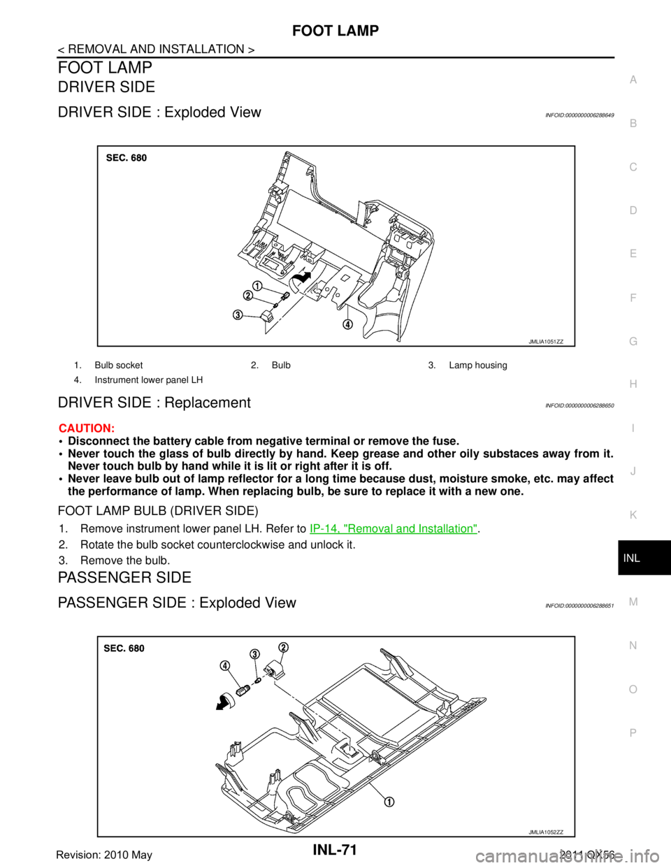
DRIVER SIDE : Exploded ViewINFOID:0000000006288649
DRIVER SIDE : ReplacementINFOID:0000000006288650
CAUTION:
Disconnect the battery cable from negative terminal or remove the fuse.
Never touch the glass of bulb directly by hand. Keep grease and other oily substaces away from it.
Never touch bulb by hand while it is lit or right after it is off.
Never leave bulb out of lamp reflector for a long time because dust, moisture smoke, etc. may affect
the performance of lamp. When replacing bu lb, be sure to replace it with a new one.
FOOT LAMP BULB (DRIVER SIDE)
1. Remove instrument lower panel LH. Refer to IP-14, "Removal and Installation".
2. Rotate the bulb socket counterclockwise and unlock it.
3. Remove the bulb.
PASSENGER SIDE
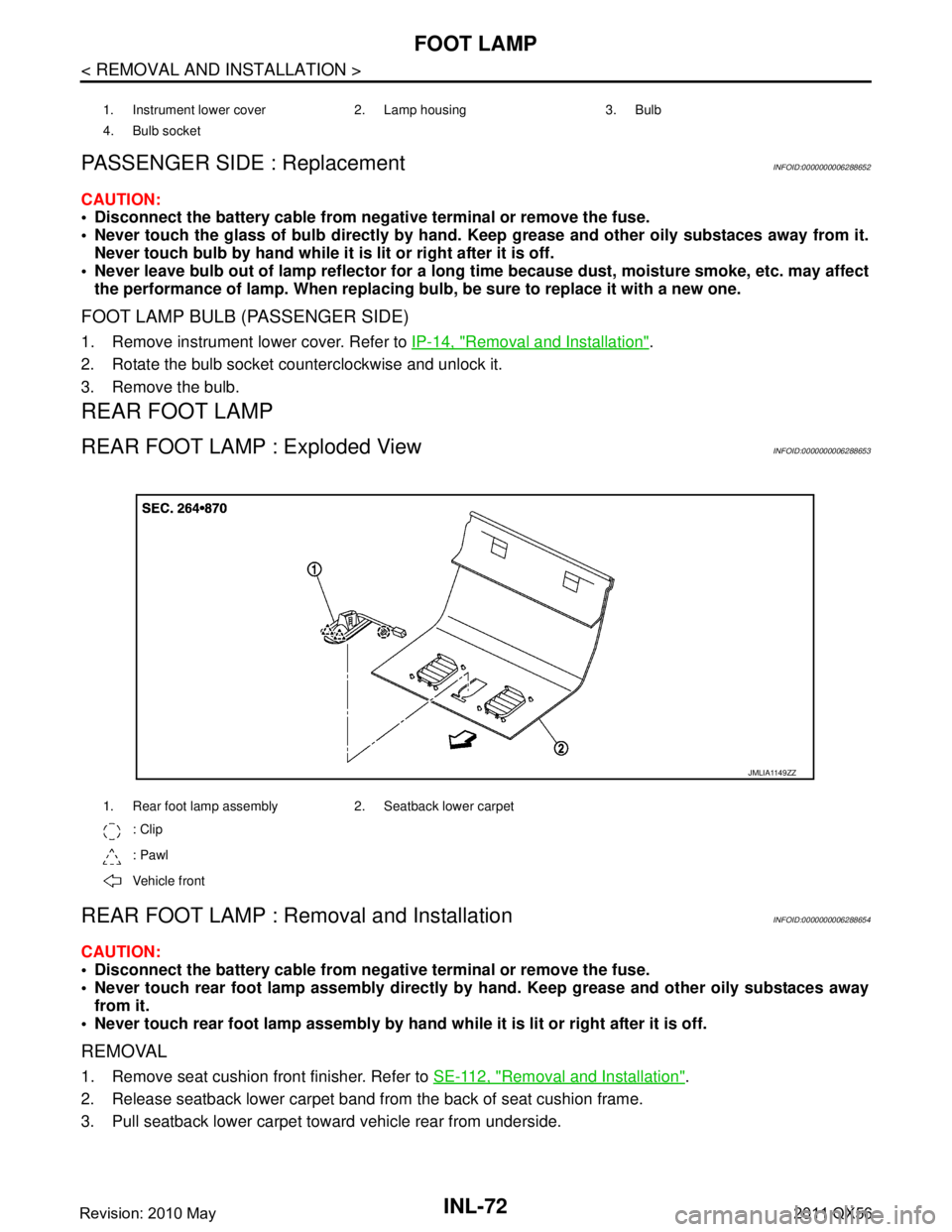
PASSENGER SIDE : Exploded ViewINFOID:0000000006288651
1. Bulb socket 2. Bulb 3. Lamp housing
4. Instrument lower panel LH
JMLIA1051ZZ
JMLIA1052ZZ
Revision: 2010 May2011 QX56
Page 3339 of 5598

INL-72
< REMOVAL AND INSTALLATION >
FOOT LAMP
PASSENGER SIDE : Replacement
INFOID:0000000006288652
CAUTION:
Disconnect the battery cable from negative terminal or remove the fuse.
Never touch the glass of bulb directly by hand. Keep grease and other oily substaces away from it.
Never touch bulb by hand while it is lit or right after it is off.
Never leave bulb out of lamp reflector for a long ti me because dust, moisture smoke, etc. may affect
the performance of lamp. When replacing bu lb, be sure to replace it with a new one.
FOOT LAMP BULB (PASSENGER SIDE)
1. Remove instrument lower cover. Refer to IP-14, "Removal and Installation".
2. Rotate the bulb socket counterclockwise and unlock it.
3. Remove the bulb.
REAR FOOT LAMP
REAR FOOT LAMP : Exploded ViewINFOID:0000000006288653
REAR FOOT LAMP : Re moval and InstallationINFOID:0000000006288654
CAUTION:
Disconnect the battery cable from negative terminal or remove the fuse.
Never touch rear foot lamp assembly directly by hand. Keep grease and other oily substaces away
from it.
Never touch rear foot lamp assembly by hand while it is lit or right after it is off.
REMOVAL
1. Remove seat cushion front finisher. Refer to SE-112, "Removal and Installation".
2. Release seatback lower carpet band fr om the back of seat cushion frame.
3. Pull seatback lower carpet toward vehicle rear from underside.
1. Instrument lower cover 2. Lamp housing 3. Bulb
4. Bulb socket
1. Rear foot lamp assembly 2. Seatback lower carpet
: Clip
: Pawl
Vehicle front
JMLIA1149ZZ
Revision: 2010 May2011 QX56