2011 FORD KUGA front
[x] Cancel search: frontPage 1859 of 2057
E127360
1
2
3
4
5
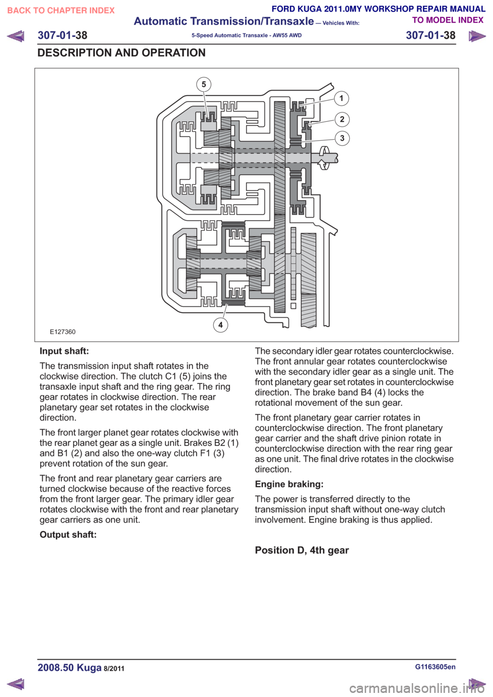
Input shaft:
The transmission input shaft rotates in the
clockwise direction. The clutch C1 (5) joins the
transaxle input shaft and the ring gear. The ring
gear rotates in clockwise direction. The rear
planetary gear set rotates in the clockwise
direction.
The front larger planet gear rotates clockwise with
the rear planet gear as a single unit. Brakes B2 (1)
and B1 (2) and also the one-way clutch F1 (3)
prevent rotation of the sun gear.
The front and rear planetary gear carriers are
turned clockwise because of the reactive forces
from the front larger gear. The primary idler gear
rotates clockwise with the front and rear planetary
gear carriers as one unit.
Output shaft:The secondary idler gear rotates counterclockwise.
The front annular gear rotates counterclockwise
with the secondary idler gear as a single unit. The
front planetary gear set rotates in counterclockwise
direction. The brake band B4 (4) locks the
rotational movement of the sun gear.
The front planetary gear carrier rotates in
counterclockwise direction. The front planetary
gear carrier and the shaft drive pinion rotate in
counterclockwise direction with the rear ring gear
as one unit. The final drive rotates in the clockwise
direction.
Engine braking:
The power is transferred directly to the
transmission input shaft without one-way clutch
involvement. Engine braking is thus applied.
Position D, 4th gear
G1163605en2008.50 Kuga8/2011
307-01-
38
Automatic Transmission/Transaxle
— Vehicles With:
5-Speed Automatic Transaxle - AW55 AWD
307-01- 38
DESCRIPTION AND OPERATION
TO MODEL INDEX
BACK TO CHAPTER INDEX
FORD KUGA 2011.0MY WORKSHOP REPAIR MANUAL
Page 1860 of 2057
E127361
1
2
3
4
5
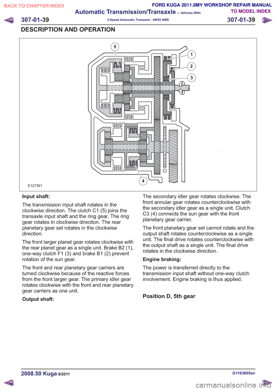
Input shaft:
The transmission input shaft rotates in the
clockwise direction. The clutch C1 (5) joins the
transaxle input shaft and the ring gear. The ring
gear rotates in clockwise direction. The rear
planetary gear set rotates in the clockwise
direction.
The front larger planet gear rotates clockwise with
the rear planet gear as a single unit. Brake B2 (1),
one-way clutch F1 (3) and brake B1 (2) prevent
rotation of the sun gear.
The front and rear planetary gear carriers are
turned clockwise because of the reactive forces
from the front larger gear. The primary idler gear
rotates clockwise with the front and rear planetary
gear carriers as one unit.
Output shaft:The secondary idler gear rotates clockwise. The
front annular gear rotates counterclockwise with
the secondary idler gear as a single unit. Clutch
C3 (4) connects the sun gear with the front
planetary gear carrier.
The front planetary gear set cannot rotate and the
output shaft rotates counterclockwise as a single
unit. The final drive rotates counterclockwise with
the output shaft as a single unit. The final drive
rotates in the clockwise direction.
Engine braking:
The power is transferred directly to the
transmission input shaft without one-way clutch
involvement. Engine braking is thus applied.
Position D, 5th gear
G1163605en2008.50 Kuga8/2011
307-01-
39
Automatic Transmission/Transaxle
— Vehicles With:
5-Speed Automatic Transaxle - AW55 AWD
307-01- 39
DESCRIPTION AND OPERATION
TO MODEL INDEX
BACK TO CHAPTER INDEX
FORD KUGA 2011.0MY WORKSHOP REPAIR MANUAL
Page 1861 of 2057
E125594
12
4
3
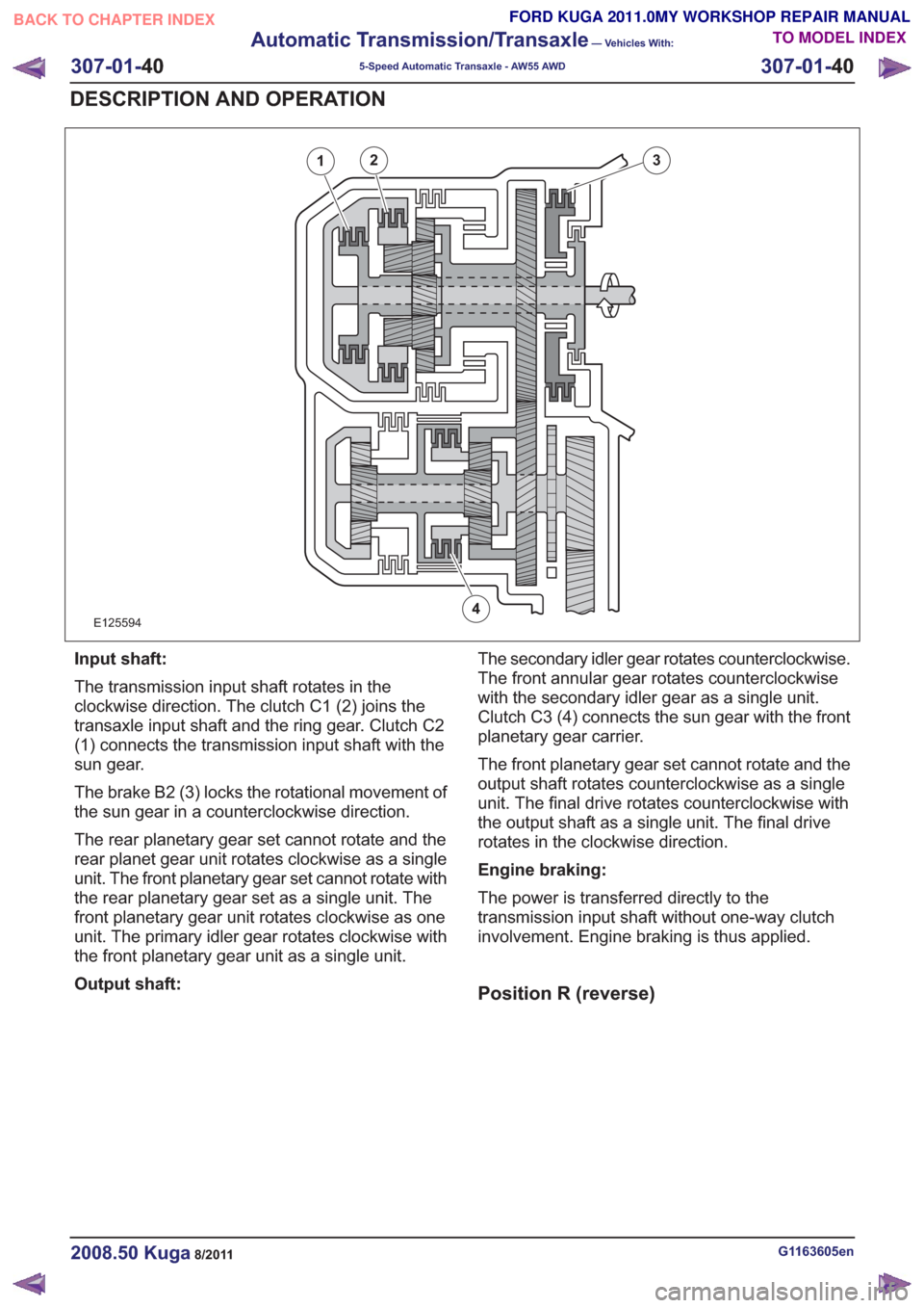
Input shaft:
The transmission input shaft rotates in the
clockwise direction. The clutch C1 (2) joins the
transaxle input shaft and the ring gear. Clutch C2
(1) connects the transmission input shaft with the
sun gear.
The brake B2 (3) locks the rotational movement of
the sun gear in a counterclockwise direction.
The rear planetary gear set cannot rotate and the
rear planet gear unit rotates clockwise as a single
unit. The front planetary gear set cannot rotate with
the rear planetary gear set as a single unit. The
front planetary gear unit rotates clockwise as one
unit. The primary idler gear rotates clockwise with
the front planetary gear unit as a single unit.
Output shaft:The secondary idler gear rotates counterclockwise.
The front annular gear rotates counterclockwise
with the secondary idler gear as a single unit.
Clutch C3 (4) connects the sun gear with the front
planetary gear carrier.
The front planetary gear set cannot rotate and the
output shaft rotates counterclockwise as a single
unit. The final drive rotates counterclockwise with
the output shaft as a single unit. The final drive
rotates in the clockwise direction.
Engine braking:
The power is transferred directly to the
transmission input shaft without one-way clutch
involvement. Engine braking is thus applied.
Position R (reverse)
G1163605en2008.50 Kuga8/2011
307-01-
40
Automatic Transmission/Transaxle
— Vehicles With:
5-Speed Automatic Transaxle - AW55 AWD
307-01- 40
DESCRIPTION AND OPERATION
TO MODEL INDEX
BACK TO CHAPTER INDEX
FORD KUGA 2011.0MY WORKSHOP REPAIR MANUAL
Page 1862 of 2057
E127362
12
3
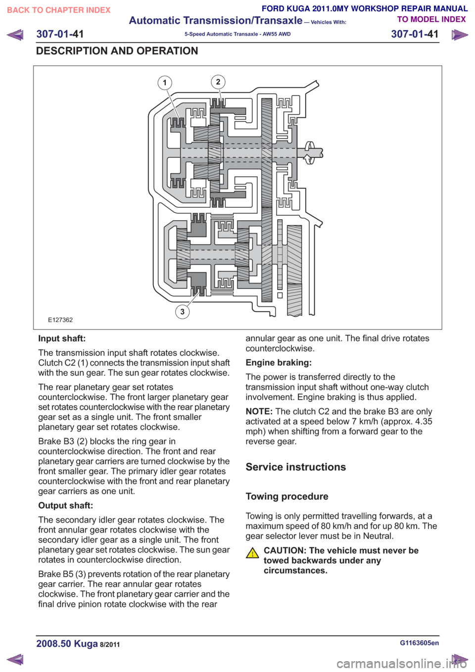
Input shaft:
The transmission input shaft rotates clockwise.
Clutch C2 (1) connects the transmission input shaft
with the sun gear. The sun gear rotates clockwise.
The rear planetary gear set rotates
counterclockwise. The front larger planetary gear
set rotates counterclockwise with the rear planetary
gear set as a single unit. The front smaller
planetary gear set rotates clockwise.
Brake B3 (2) blocks the ring gear in
counterclockwise direction. The front and rear
planetary gear carriers are turned clockwise by the
front smaller gear. The primary idler gear rotates
counterclockwise with the front and rear planetary
gear carriers as one unit.
Output shaft:
The secondary idler gear rotates clockwise. The
front annular gear rotates clockwise with the
secondary idler gear as a single unit. The front
planetary gear set rotates clockwise. The sun gear
rotates in counterclockwise direction.
Brake B5 (3) prevents rotation of the rear planetary
gear carrier. The rear annular gear rotates
clockwise. The front planetary gear carrier and the
final drive pinion rotate clockwise with the rearannular gear as one unit. The final drive rotates
counterclockwise.
Engine braking:
The power is transferred directly to the
transmission input shaft without one-way clutch
involvement. Engine braking is thus applied.
NOTE:
The clutch C2 and the brake B3 are only
activated at a speed below 7 km/h (approx. 4.35
mph) when shifting from a forward gear to the
reverse gear.
Service instructions
Towing procedure
Towing is only permitted travelling forwards, at a
maximum speed of 80 km/h and for up 80 km. The
gear selector lever must be in Neutral.
CAUTION: The vehicle must never be
towed backwards under any
circumstances.
G1163605en2008.50 Kuga8/2011
307-01- 41
Automatic Transmission/Transaxle
— Vehicles With:
5-Speed Automatic Transaxle - AW55 AWD
307-01- 41
DESCRIPTION AND OPERATION
TO MODEL INDEX
BACK TO CHAPTER INDEX
FORD KUGA 2011.0MY WORKSHOP REPAIR MANUAL
Page 1868 of 2057
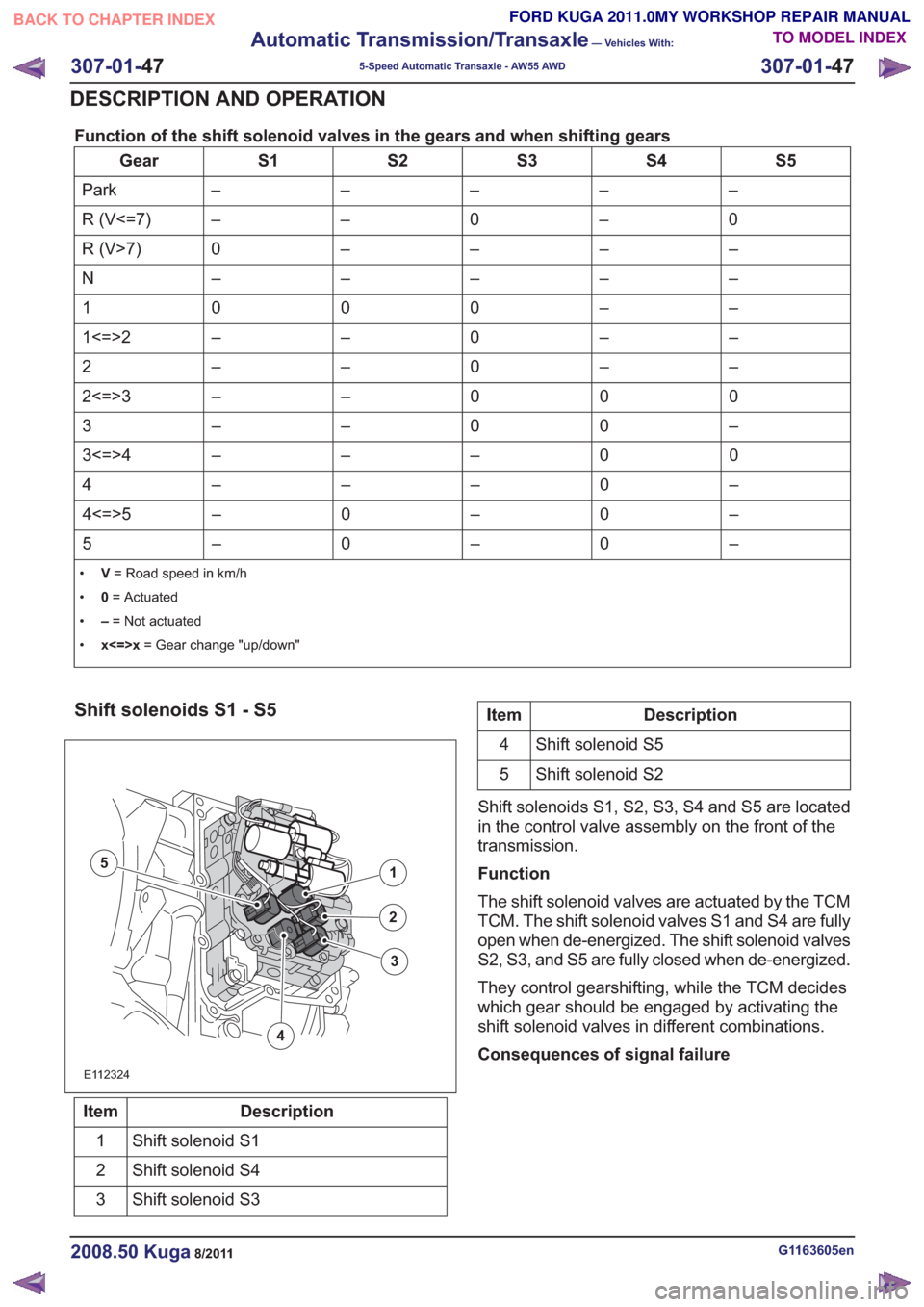
Function of the shift solenoid valves in the gears and when shifting gears
S5
S4
S3
S2
S1
Gear
–
–
–
–
–
Park
0
–
0
–
–
R (V<=7)
–
–
–
–
0
R (V>7)
–
–
–
–
–
N
–
–
0
0
0
1
–
–
0
–
–
1<=>2
–
–
0
–
–
2
0
0
0
–
–
2<=>3
–
0
0
–
–
3
0
0
–
–
–
3<=>4
–
0
–
–
–
4
–
0
–
0
–
4<=>5
–
0
–
0
–
5
• V= Road speed in km/h
• 0= Actuated
• –= Not actuated
• x<=>x = Gear change "up/down"
Shift solenoids S1 - S5
E112324
1
2
4
5
3
Description
Item
Shift solenoid S1
1
Shift solenoid S4
2
Shift solenoid S3
3
Description
Item
Shift solenoid S5
4
Shift solenoid S2
5
Shift solenoids S1, S2, S3, S4 and S5 are located
in the control valve assembly on the front of the
transmission.
Function
The shift solenoid valves are actuated by the TCM
TCM. The shift solenoid valves S1 and S4 are fully
open when de-energized. The shift solenoid valves
S2, S3, and S5 are fully closed when de-energized.
They control gearshifting, while the TCM decides
which gear should be engaged by activating the
shift solenoid valves in different combinations.
Consequences of signal failure
G1163605en2008.50 Kuga8/2011
307-01- 47
Automatic Transmission/Transaxle
— Vehicles With:
5-Speed Automatic Transaxle - AW55 AWD
307-01- 47
DESCRIPTION AND OPERATION
TO MODEL INDEX
BACK TO CHAPTER INDEX
FORD KUGA 2011.0MY WORKSHOP REPAIR MANUAL
Page 1870 of 2057
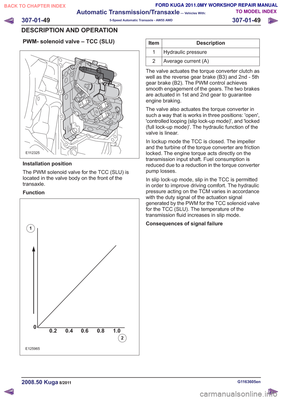
PWM- solenoid valve – TCC (SLU)
E112325
Installation position
The PWM solenoid valve for the TCC (SLU) is
located in the valve body on the front of the
transaxle.
Function
00.2 1.0 0.80.60.4
0
0.2 1.0
0.80.60.4
0
0.2 1.0
0.80.60.40
0.2 1.0 0.80.60.4
E125965
1
2
Description
Item
Hydraulic pressure
1
Average current (A)
2
The valve actuates the torque converter clutch as
well as the reverse gear brake (B3) and 2nd - 5th
gear brake (B2). The PWM control achieves
smooth engagement of the gears. The two brakes
are actuated in 1st and 2nd gear to guarantee
engine braking.
The valve also actuates the torque converter in
such a way that is works in three positions: 'open',
'controlled looping (slip lock-up mode)', and 'locked
(full lock-up mode)'. The hydraulic function of the
valve is linear.
In lockup mode the TCC is closed. The impeller
and the turbine of the torque converter are friction
locked. The engine torque acts directly on the
transmission input shaft. Fuel consumption is
reduced due to a reduction in the torque converter
pump losses.
In slip lock-up mode, slip in the TCC is permitted
in order to improve driving comfort. The hydraulic
pressure acting on the TCM varies in accordance
with the duty signal of the actuation signal
generated by the PWM for the TCC solenoid valve
for the TCC (SLU). The temperature of the
transmission fluid increases in slip mode.
Consequences of signal failure
G1163605en2008.50 Kuga8/2011
307-01- 49
Automatic Transmission/Transaxle
— Vehicles With:
5-Speed Automatic Transaxle - AW55 AWD
307-01- 49
DESCRIPTION AND OPERATION
TO MODEL INDEX
BACK TO CHAPTER INDEX
FORD KUGA 2011.0MY WORKSHOP REPAIR MANUAL
Page 1871 of 2057
E125966
97
2
1
Description
Item
PWM- solenoid valve – TCC (SLU)
1
TCM connector 'C'
2
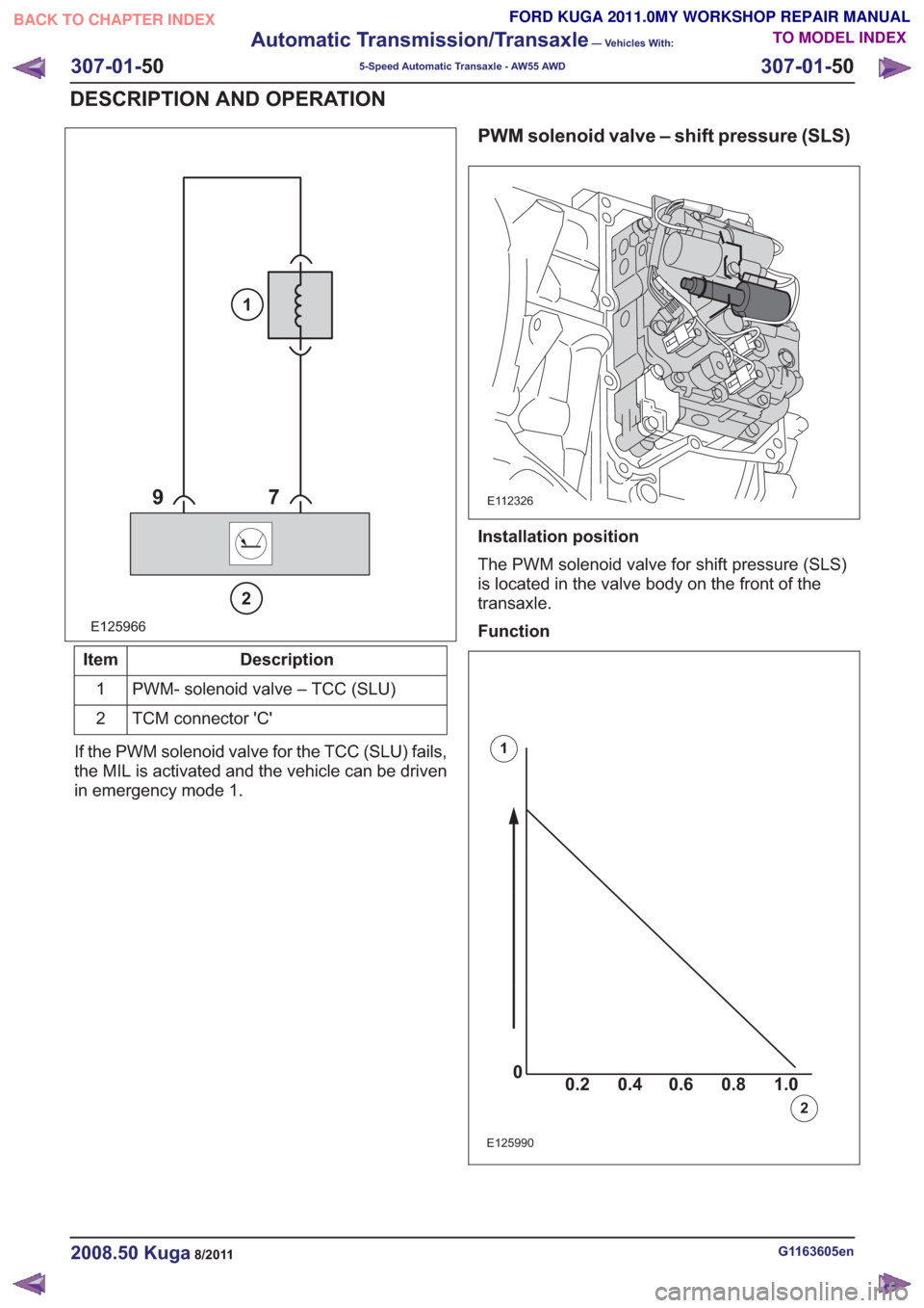
If the PWM solenoid valve for the TCC (SLU) fails,
the MIL is activated and the vehicle can be driven
in emergency mode 1.
PWM solenoid valve – shift pressure (SLS)
E112326
Installation position
The PWM solenoid valve for shift pressure (SLS)
is located in the valve body on the front of the
transaxle.
Function
0 0.2 1.00.80.60.4
0
0.2 1.00.80.60.4
0
0.2 1.00.80.60.40
0.2 1.00.80.60.4
E125990
1
2
G1163605en2008.50 Kuga8/2011
307-01- 50
Automatic Transmission/Transaxle
— Vehicles With:
5-Speed Automatic Transaxle - AW55 AWD
307-01- 50
DESCRIPTION AND OPERATION
TO MODEL INDEX
BACK TO CHAPTER INDEX
FORD KUGA 2011.0MY WORKSHOP REPAIR MANUAL
Page 1872 of 2057
Description
Item
Hydraulic pressure
1
Average current (A)
2
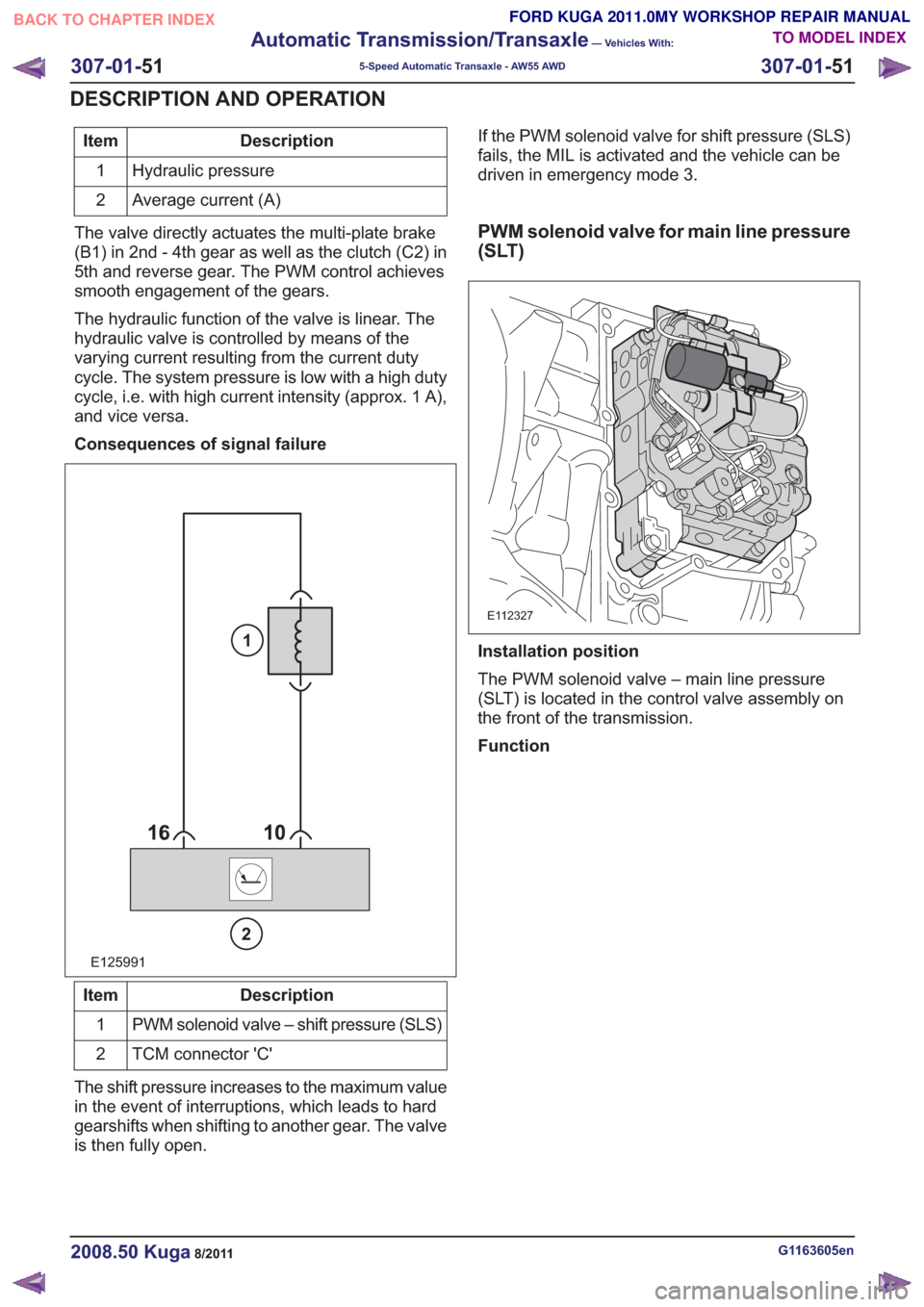
The valve directly actuates the multi-plate brake
(B1) in 2nd - 4th gear as well as the clutch (C2) in
5th and reverse gear. The PWM control achieves
smooth engagement of the gears.
The hydraulic function of the valve is linear. The
hydraulic valve is controlled by means of the
varying current resulting from the current duty
cycle. The system pressure is low with a high duty
cycle, i.e. with high current intensity (approx. 1 A),
and vice versa.
Consequences of signal failure
E125991
2
1
Description
Item
PWM solenoid valve – shift pressure (SLS)
1
TCM connector 'C'
2
The shift pressure increases to the maximum value
in the event of interruptions, which leads to hard
gearshifts when shifting to another gear. The valve
is then fully open. If the PWM solenoid valve for shift pressure (SLS)
fails, the MIL is activated and the vehicle can be
driven in emergency mode 3.
PWM solenoid valve for main line pressure
(SLT)
E112327
Installation position
The PWM solenoid valve – main line pressure
(SLT) is located in the control valve assembly on
the front of the transmission.
Function
G1163605en2008.50 Kuga8/2011
307-01-
51
Automatic Transmission/Transaxle
— Vehicles With:
5-Speed Automatic Transaxle - AW55 AWD
307-01- 51
DESCRIPTION AND OPERATION
TO MODEL INDEX
BACK TO CHAPTER INDEX
FORD KUGA 2011.0MY WORKSHOP REPAIR MANUAL