2011 FORD KUGA Locks
[x] Cancel search: LocksPage 60 of 2057

Standard Workshop Practices
Vehicle in Workshop
When working on a vehicle in the workshop always
make sure that:
– the parking brake is applied or the wheels aresecurely chocked to prevent the vehicle moving
forwards or backwards.
– the key is removed from key operated hood locks before any work is carried out around the
front of the vehicle.
– if the engine is to be run, there is adequate ventilation, or an extraction hose to remove
exhaust fumes.
– there is adequate room to raise the vehicle and remove the wheels, if necessary.
– fender covers are always fitted if any work is to be carried out in the engine compartment.
– the battery is disconnected if working on the engine, underneath the vehicle, or if the vehicle
is raised.
CAUTION: When electric arc welding on a
vehicle, always disconnect the generator
wiring to prevent the possibility of a surge
of current causing damage to the internal
components of the generator.
– if using welding equipment on the vehicle, a suitable fire extinguisher is readily available.
Towing the Vehicle
WARNING: When the vehicle is being
towed, the ignition switch must be in
position II (steering lock released and
warning lamps illuminated). Only then will
the steering, turn signal lamps, horn and
stop lamps be operational. Failure to follow
these instructions may result in personal
injury.
NOTE: The removable towing eye (if equipped),
has a left-hand thread and must be fully tightened
before towing can commence.
When towing is necessary, the vehicle towing eyes
should be used. The rope must be securely
fastened to the towing eyes and must also be
attached to the other vehicle such that the rope will
not foul the bodywork.
When a vehicle with automatic transmission is
towed, the gear selector must be in position N (Neutral). Never tow a vehicle with automatic
transmission at a speed greater than 30 mph (50
km/h) or for a distance greater than 30 miles (50
km). If it is necessary to tow the vehicle a greater
distance, the drive wheels must be lifted clear off
the ground.
Alternatively the vehicle can be transported on a
low loader or a trailer.
Connecting a Slave Battery Using
Jumper Cables
WARNING: If the slave battery has recently
been charged and is gassing, cover the
vent plugs or covers with a damp cloth to
reduce the risk of explosion should arcing
occur when connecting the jumper cables.
Failure to follow these instructions may
result in personal injury.
CAUTIONS:
A discharged battery condition may have
been caused by an electrical short circuit.
If this condition exists there will be an
apparently live circuit on the vehicle even
when all normal circuits are switched off.
This can cause arcing when the jumper
cables are connected.
While it is not recommended that the
vehicle is jump started, it is recognized
that this may occasionally be the only
practical way to mobilize a vehicle. In such
an instance, the discharged battery must
be recharged immediately after jump
starting to avoid permanent damage.
– Always make sure that the jumper cables are adequate for the task. Heavy duty cables must
be used.
– Always make sure that the slave battery is of the same voltage as the vehicle battery. The
batteries must be connected in parallel.
– Always make sure that switched electric circuits are switched off before connecting jumper
cables. This reduces the risk of arcing occurring
when the final connection is made.
G17373en2008.50 Kuga8/2011
100-00- 54
General Information
100-00- 54
DESCRIPTION AND OPERATION
TO MODEL INDEX
BACK TO CHAPTER INDEX
FORD KUGA 2011.0MY WORKSHOP REPAIR MANUAL
Page 87 of 2057

Action
Possible Sources
Symptom
CHECK the installation and
potential damage of the floor
seal.
Floor seal.
NOTE:
Engine speed at idle
turning the steering wheel slowly
lock to lock.
Power steering system hiss noise
– a high frequency, continuous
rush or swish noise like escaping
air from a balloon. Hiss occurs
while turning between the
steering lock stops, all steering
angles. Noise does not change
with engine rpm and is worse at
high operating temperatures. Certain amount of noise level
acceptable, not a safety critical
item.
Power steering gear valve
design.
Certain amount of noise level
acceptable, not a safety critical
item.
Power steering system hydraulic
design.
Certain amount of noise level
acceptable, not a safety critical
item.
Power steering pump pressure
relief valve.
NOTE:
Engine speed at idle
holding the steering wheel
against a steering lock for three
seconds. Do not hold for more
than five seconds.
Power steering system hiss noise
– a continuous noise like
escaping air occurs while holding
the steering against a steering
lock stop.
Power Steering Lock Stop Impact Knock
Noise
Test Condition
Listen for steering knock noise with the engine
speed at idle in the following test conditions (noise
also apparent with engine off). 1. Turn the steering wheel to the left-hand and
right-hand steering locks and listen for the
impact noise.
Action
Possible Sources
Symptom
Certain amount of noise level
acceptable, not a safety critical
item.
Power steering gear mechanical
noise, metal to metal at end of
steering travel.
Power steering system knock
noise – a heavy loud sound like
a knock on a door that occurs in
parking condition when hitting the
lock stop.
Power Steering Mechanical Knock Noise
(PAS off)
Test Condition
Listen for steering knock noise with the engine off
in the following test conditions (no power assist). 1. Turn the steering wheel 90 degrees to the right,
hold and then quickly release.
2. Turn the steering wheel 90 degrees to the left, hold and then quickly release.
G37349en2008.50 Kuga8/2011
100-04- 9
Noise, Vibration and Harshness
100-04- 9
DIAGNOSIS AND TESTING
TO MODEL INDEX
BACK TO CHAPTER INDEX
FORD KUGA 2011.0MY WORKSHOP REPAIR MANUAL
Page 91 of 2057

Action
Possible Sources
Symptom
Certain amount of noise level
acceptable, not a safety critical
item.
Steering wheel to shroud interfer-
ence.
Power steering system grinding
noise – an abrasive noise (like
sand paper rubbing against
wood) occurs between moving
components such as steering
wheel and the steering column
shroud. Certain amount of noise level
acceptable, not a safety critical
item.
Steering column bearing.
CHECK if floor covering is
obstructing the steering gear
pinion.
Foreign material in contact with
the steering column shaft.
CHECK the installation of the
floor seal.
CHECK the clockspring and
secure if necessary.
REFER to:Clockspring (501-20
Supplemental Restraint
System, Removal and Installa-
tion).
Clockspring.
Power Steering Zip Noise
Action
Possible Sources
Symptom
Certain amount of noise level
acceptable, not a safety critical
item.
High viscosity of power steering
fluid at low temperature.
Power steering system zip noise
– occurs when hydraulic fluid
does not flow freely through the
power steering pump supply hose
from steering fluid reservoir to
power steering pump causing
cavitation at the pump. Zip is
primarily a cold weather start-up
phenomenon (below -10°C). BLEED the power steering
system.
REFER to:
Power Steering
System Vacuum Bleeding (211-
00 Steering System - General
Information, General Proced-
ures).
Aeration of the power steering
fluid.
Driveline Noise and Vibration
Action
Possible Sources
Symptom
GO toPinpoint Test A.
• Wheel end vibration.
• Engine/transmission.
Shake and vibration while driving
GO toPinpoint Test B.
• Air cleaner.
• Power assisted steering.
• Powertrain.
• Powertrain/drivetrain mounts.
• Exhaust system.
Tip-in moan
G37349en2008.50 Kuga8/2011
100-04-
13
Noise, Vibration and Harshness
100-04- 13
DIAGNOSIS AND TESTING
TO MODEL INDEX
BACK TO CHAPTER INDEX
FORD KUGA 2011.0MY WORKSHOP REPAIR MANUAL
Page 195 of 2057

Horn
Principles of Operation
The horn system consists of a relay, a steering
wheel switch and either one or two horns. The
horn(s) receives voltage from the switched side of
the relay, and the relay switch is controlled on its
ground side by the steering wheel switch.
The horn relay, is located in the Battery junction
box (BJB) and is supplied with a permanent voltage
from the battery.
The steering wheel horn switch shares the steering
wheel clockspring circuit with the air-bag circuit.
Each of these systems work completely
independent of each other.
Inspection and Verification
1. Verify the customer concern.
2.
Visually inspect for obvious signs of mechanical
or electrical damage.
Visual Inspection Chart Electrical
• Fuse(s)
• Wiring harness
• Electrical connector(s)
• Horn switch
• Horn
• Clockspring
• Horn relay
• BJB
3. If an obvious cause for an observed or reported concern is found, correct the cause (if possible)
before proceeding to the next step.
4. If the cause is not visually evident, verify the symptom and refer to the diagnostic tab within
the Ford approved diagnostic tool. G1055042en
2008.50 Kuga 8/2011 413-06-2
Horn
413-06-2
DIAGNOSIS AND TESTINGTO MODEL INDEX
BACK TO CHAPTER INDEX
FORD KUGA 2011.0MY WORKSHOP REPAIR MANUAL
Page 383 of 2057

Description
Item
Medium speed CAN (controller area
network) bus (MS-CAN)
A
High speed CAN bus (HS-CAN)
B
LIN (local interconnect network) bus
C
Terminating resistors
Drive
DLC (data link connector)
E
GEMRefer to Component Description: ABS
(page ?)
1
Fuel fired booster heater /programmable
fuel fired booster heater
2
The EATC control module
3
Reversing camera module (RVC)
4
Parking aid module (PAM)
5
DDM6
Front driver's side switch unit
7
Driver's side RDM
8
PDM (Passenger Door Module)
9
Passenger side RDM
10
Audio unit/navigation unit
11
CD changer
12 Description
Item
Navigation system module - vehicles
equipped with DVD navigation system with
touch screen (not communicating with the
diagnostic unit)
13
Navigation system display - vehicles
equipped with DVD navigation system with
touch screen (not communicating with the
diagnostic unit)
14
Control module for electronic auxiliary
equipment (BVC)
15
RCM16
Keyless vehicle module (KVM)
17
Instrument Cluster
18
PCM19
Fuel additive system module.
20
ABS module or electronic stability program
module
21
Yaw rate sensor/lateral acceleration
sensor
22
Headlamp Leveling Module
23
All-wheel drive control unit
24
Electrohydraulic power steering module
25
System Operation
General
In a communications network (data bus system),
various modules of different systems are connected
to one another via one or several lines.
The data bus system is used exclusively for
transmitting data between the connected modules,
as well as between the connected modules and
the Ford diagnostic unit.
In a data bus system, complete data blocks are
transmitted instead of single on/off pulses. In
addition to the actual information, these data blocks
also contain data regarding the address of the
module to be addressed, the size of the data block
and information for monitoring the content of each
individual data block.
Data bus systems offer various advantages: • Simplified data transmission between the
modules due to a standardized protocol
• Fewer sensors and connectors
• Improved diagnostic options
• Lower costs
The DLC is connected to the various data bus
systems and to the power supply via the standard
16-pin GEM. The signal for the module
programming is also transferred via the DLC.
In a data bus system, if there is a break in one or
both lines or there is a short to ground or to voltage,
then communication between the modules and
with the Ford diagnostic unit is disturbed or is no
longer possible at all.
In order to be able to establish communication with
one another, the modules of the individual systems G1030779en
2008.50 Kuga 8/2011 418-00-6
Module Communications Network
418-00-6
DESCRIPTION AND OPERATIONTO MODEL INDEX
BACK TO CHAPTER INDEX
FORD KUGA 2011.0MY WORKSHOP REPAIR MANUAL
Page 438 of 2057

Description
Item
High speed CAN (controller area network)
bus (HS-CAN)
1
DLC (data link connector)
2
Medium speed CAN bus (MS-CAN)
3
Instrument cluster (gateway)
4
GEM5
Hood contact switch
6
Folding rear window contact switch
7
Liftgate contact switch
8
Door ajar switch in all four doors
9
Switch for deactivation of interior scanning
sensors (right-hand drive vehicles)
10
Interior scanning sensorsRefer to Component Description: (page
?)
11 Description
Item
Driver's door set/reset switch
12
Driver's door door module
13
Keyless vehicle module (KVM)
14
RF receiver
15
Radio remote control
16
Anti-theft alarm system signal horn
(left-hand drive vehicles)
17
Anti-theft alarm system horn with
integrated battery (right-hand drive
vehicles)Refer to Component Description:
Anti-theft alarm horn with integral battery
(page ?)
18
Hazard warning lights
19
System Operation
Anti-theft warning system
Three anti-theft alarm systems are available,
depending on the market and model version:
• The system with perimeter monitoring detects whenever the doors, the hood, the folding rear
window and the liftgate are opened.
• The system with perimeter and interior monitoring in addition detects unauthorised
access, for example, through a broken window.
• A Thatcham category I anti-theft alarm system (mainly for the British market) is fitted with a
horn that has its own battery power supply; it
also uses slightly different detection strategies.
The anti-theft alarm system outputs an acoustic
and visual signal if unauthorised persons attempt
to gain access to the vehicle.
As a visual warning, the system switches on the
hazard warning lights, whilst the acoustic warning
is done with the anti-theft alarm system horn or the
horn with its own battery power supply.
When the ignition is switched off, the anti-theft
alarm system is activated 20 seconds after any
latch is activated, i.e. the hood, all doors, the
folding rear window and the liftgate are alarmed,
provided that they are fully closed. If the hood, one of the doors, the folding rear
window or the liftgate is not completely closed, it
can be opened without the alarm being triggered
since the system was not activated.
The anti-theft alarm system can be switched off by
unlocking the vehicle either via the remote controls
or the door lock.
NOTE:
To switch off the alarm on a Thatcham
category I anti-theft alarm system, the ignition must
be switched on within 12 seconds of the door being
unlocked with the key.
If the folding rear window or the liftgate is opened
via the remote control, the anti-theft alarm system
blocks the trigger for the alarm system or the
interior monitoring (if fitted) for 20 seconds after
closing.
NOTE: If a window is not fully closed, there is a
risk that a false alarm will be triggered. G1065780en
2008.50 Kuga 8/2011 419-01A-6
Anti-Theft - Active
419-01A-6
DESCRIPTION AND OPERATIONTO MODEL INDEX
BACK TO CHAPTER INDEX
FORD KUGA 2011.0MY WORKSHOP REPAIR MANUAL
Page 1424 of 2057

Vehicles with ESP are equipped with an
opto-electronic steering wheel rotation sensor as
an integral part of the clockspring.
The following must be taken into account when
removing/installing or replacing the opto-electronic
steering wheel rotation sensor:
• If installing a new clockspring, remove theclockspring locking screw.
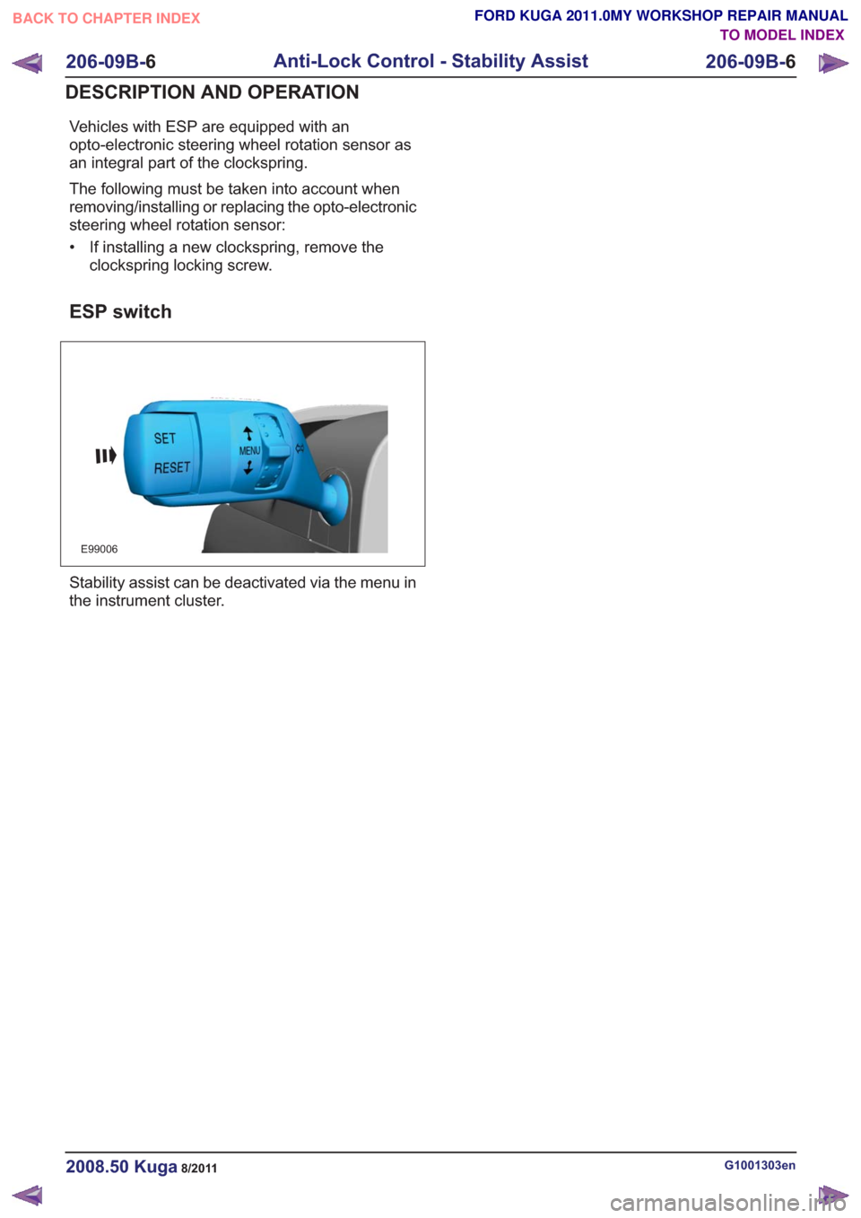
ESP switch
E99006
Stability assist can be deactivated via the menu in
the instrument cluster.
G1001303en2008.50 Kuga8/2011
206-09B- 6
Anti-Lock Control - Stability Assist
206-09B- 6
DESCRIPTION AND OPERATION
TO MODEL INDEX
BACK TO CHAPTER INDEX
FORD KUGA 2011.0MY WORKSHOP REPAIR MANUAL
Page 1504 of 2057

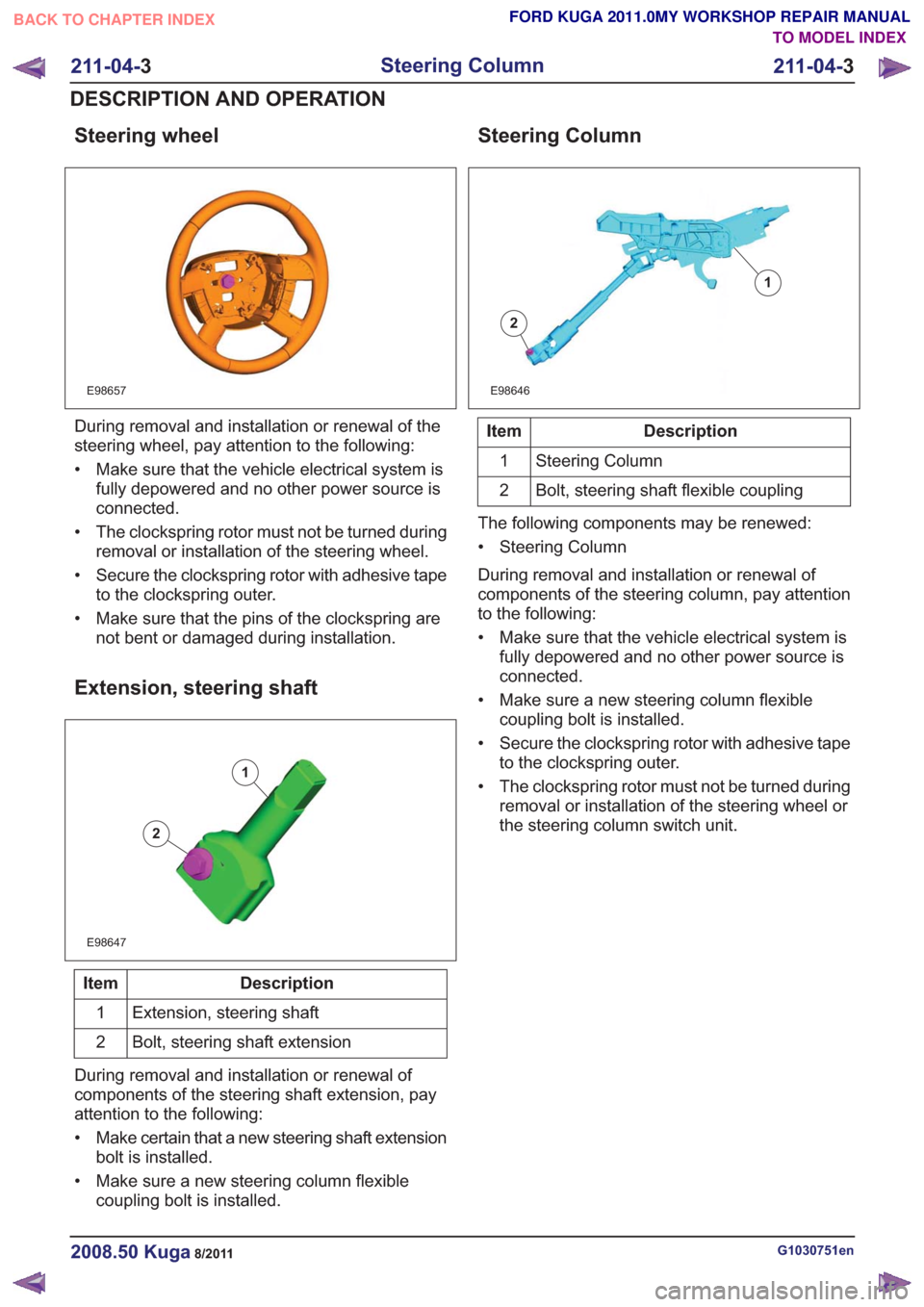
Steering wheel
E98657
During removal and installation or renewal of the
steering wheel, pay attention to the following:
• Make sure that the vehicle electrical system isfully depowered and no other power source is
connected.
• The clockspring rotor must not be turned during removal or installation of the steering wheel.
• Secure the clockspring rotor with adhesive tape to the clockspring outer.
• Make sure that the pins of the clockspring are not bent or damaged during installation.
Extension, steering shaft
E98647
1
2
Description
Item
Extension, steering shaft
1
Bolt, steering shaft extension
2
During removal and installation or renewal of
components of the steering shaft extension, pay
attention to the following:
• Make certain that a new steering shaft extension bolt is installed.
• Make sure a new steering column flexible coupling bolt is installed.
Steering Column
E98646
1
2
Description
Item
Steering Column
1
Bolt, steering shaft flexible coupling
2
The following components may be renewed:
• Steering Column
During removal and installation or renewal of
components of the steering column, pay attention
to the following:
• Make sure that the vehicle electrical system is fully depowered and no other power source is
connected.
• Make sure a new steering column flexible coupling bolt is installed.
• Secure the clockspring rotor with adhesive tape to the clockspring outer.
• The clockspring rotor must not be turned during removal or installation of the steering wheel or
the steering column switch unit.
G1030751en2008.50 Kuga8/2011
211-04- 3
Steering Column
211-04- 3
DESCRIPTION AND OPERATION
TO MODEL INDEX
BACK TO CHAPTER INDEX
FORD KUGA 2011.0MY WORKSHOP REPAIR MANUAL