2011 FORD KUGA front
[x] Cancel search: frontPage 1528 of 2057
TIE44583
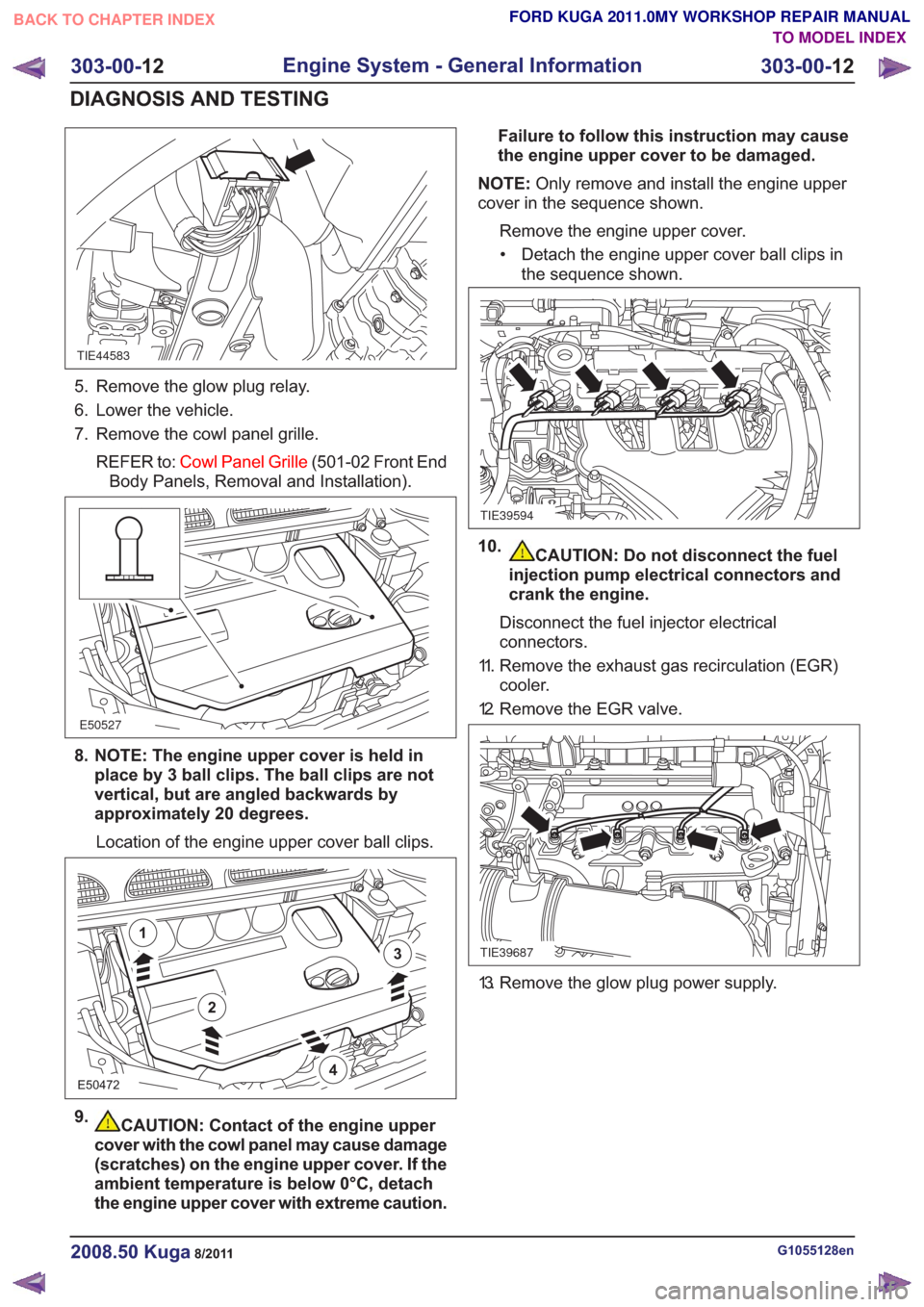
5. Remove the glow plug relay.
6. Lower the vehicle.
7. Remove the cowl panel grille.REFER to: Cowl Panel Grille (501-02 Front End
Body Panels, Removal and Installation).
E50527
8. NOTE: The engine upper cover is held in place by 3 ball clips. The ball clips are not
vertical, but are angled backwards by
approximately 20 degrees.
Location of the engine upper cover ball clips.
E50472
2
1
3
4
9.CAUTION: Contact of the engine upper
cover with the cowl panel may cause damage
(scratches) on the engine upper cover. If the
ambient temperature is below 0°C, detach
the engine upper cover with extreme caution. Failure to follow this instruction may cause
the engine upper cover to be damaged.
NOTE: Only remove and install the engine upper
cover in the sequence shown.
Remove the engine upper cover.• Detach the engine upper cover ball clips in the sequence shown.
TIE39594
10.CAUTION: Do not disconnect the fuel
injection pump electrical connectors and
crank the engine.
Disconnect the fuel injector electrical
connectors.
11. Remove the exhaust gas recirculation (EGR) cooler.
12. Remove the EGR valve.
TIE39687
13. Remove the glow plug power supply.
G1055128en2008.50 Kuga8/2011
303-00- 12
Engine System - General Information
303-00- 12
DIAGNOSIS AND TESTING
TO MODEL INDEX
BACK TO CHAPTER INDEX
FORD KUGA 2011.0MY WORKSHOP REPAIR MANUAL
Page 1530 of 2057
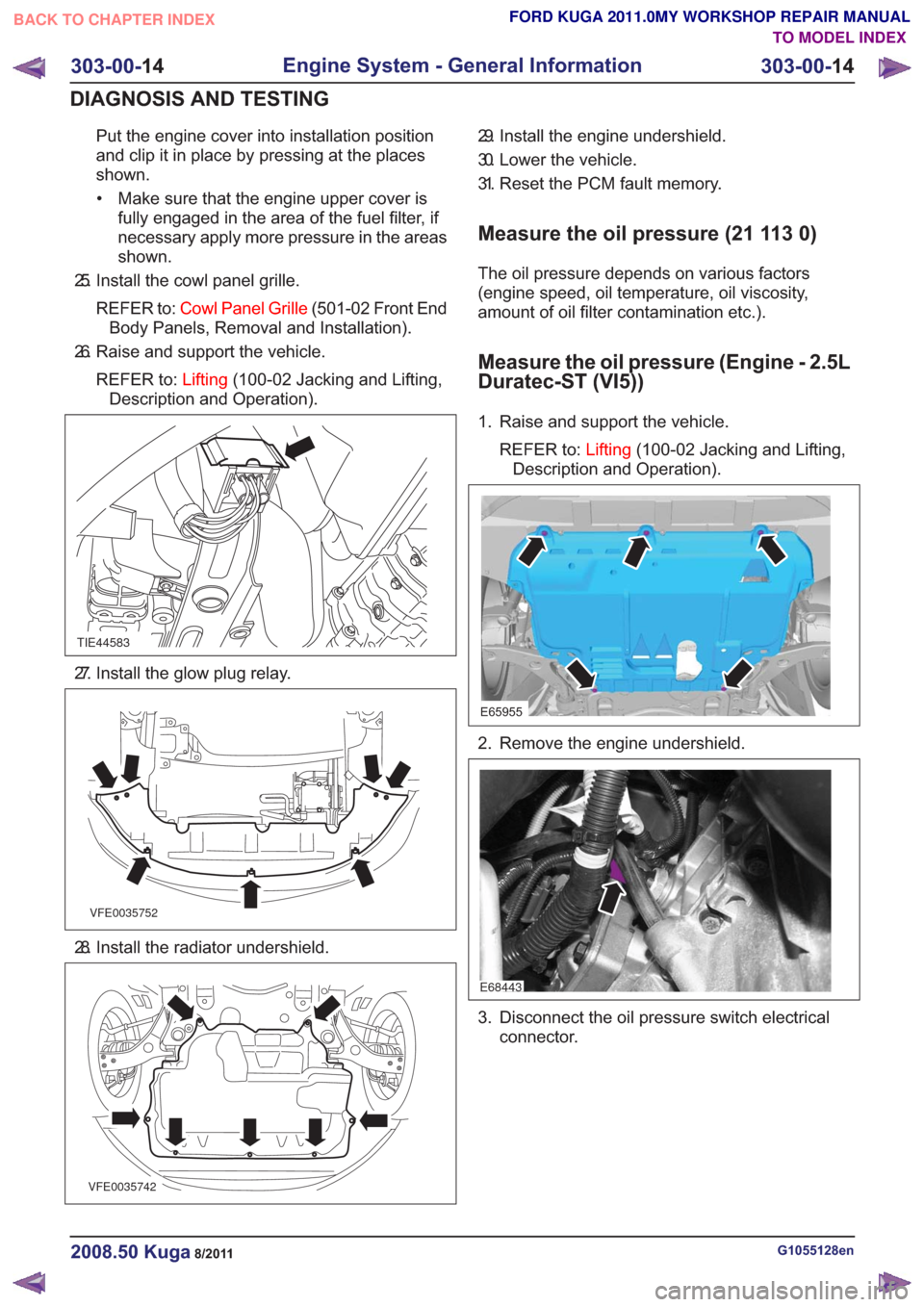
Put the engine cover into installation position
and clip it in place by pressing at the places
shown.• Make sure that the engine upper cover is fully engaged in the area of the fuel filter, if
necessary apply more pressure in the areas
shown.
25. Install the cowl panel grille.
REFER to: Cowl Panel Grille (501-02 Front End
Body Panels, Removal and Installation).
26. Raise and support the vehicle.
REFER to: Lifting(100-02 Jacking and Lifting,
Description and Operation).
TIE44583
27. Install the glow plug relay.
VFE0035752
28. Install the radiator undershield.
VFE0035742
29. Install the engine undershield.
30. Lower the vehicle.
31. Reset the PCM fault memory.
Measure the oil pressure (21 113 0)
The oil pressure depends on various factors
(engine speed, oil temperature, oil viscosity,
amount of oil filter contamination etc.).
Measure the oil pressure (Engine - 2.5L
Duratec-ST (VI5))
1. Raise and support the vehicle.
REFER to: Lifting(100-02 Jacking and Lifting,
Description and Operation).
E65955
2. Remove the engine undershield.
E68443
3. Disconnect the oil pressure switch electrical connector.
G1055128en2008.50 Kuga8/2011
303-00- 14
Engine System - General Information
303-00- 14
DIAGNOSIS AND TESTING
TO MODEL INDEX
BACK TO CHAPTER INDEX
FORD KUGA 2011.0MY WORKSHOP REPAIR MANUAL
Page 1534 of 2057
SECTION 303-01 Engine— 2.5L Duratec (147kW/200PS) - VI5
VEHICLE APPLICATION:2008.50 Kuga
PA G E
CONTENTS
SPECIFICATIONS
303-01-3
Specifications ........................................................................\
..............................................
303-01-3
Engine Data ........................................................................\
............................................
303-01-3
Engine Oil ........................................................................\
...............................................
303-01-3
Engine Oil Capacity ........................................................................\
................................
303-01-3
Oil Pressure ........................................................................\
............................................
303-01-4
Valve Clearance ........................................................................\
......................................
303-01-4
Crankshaft Main Bearing Selection ........................................................................\
........
DESCRIPTION AND OPERATION 303-01-6
Engine (Component Location) ........................................................................\
....................
303-01-9
Engine (Overview) ........................................................................\
......................................
303-01-9
General ........................................................................\
.......................................................
303-01-10
Cylinder head ........................................................................\
.............................................
303-01-14
Cylinder block ........................................................................\
.............................................
303-01-16
Engine (System Operation and Component Description) ...................................................
303-01-16
System Operation ........................................................................\
.......................................
303-01-17
Variable camshaft timing ........................................................................\
.........................
GENERAL PROCEDURES 303-01-19
Valve Clearance Adjustment ........................................................................\
.......................
REMOVAL AND INSTALLATION 303-01-20
(21 183 0)
Intake Manifold ........................................................................\
.......................
303-01-22
(21 467 0)
Crankshaft Front Seal ........................................................................\
.............
303-01-23
(21 238 0)
Valve Stem Seals ........................................................................\
...................
303-01-25
(21 304 0)
Timing Belt ........................................................................\
..............................
303-01-31
(21 284 0)
Camshafts ........................................................................\
..............................
303-01-36
(21 288 0)
Camshaft Seal ........................................................................\
........................
303-01-45
(21 154 0)
Oil Pan ........................................................................\
....................................
303-01-48
(21 714 0)
Oil Pump ........................................................................\
.................................
303-01-49
(21 187 0)
Exhaust Manifold ........................................................................\
....................
303-01-50
(21 163 0)
Cylinder Head ........................................................................\
.........................
303-01-56
(21 468 4)
Crankshaft Rear Seal ........................................................................\
.............
303-01-58
(21 764 0)
Oil Cooler ........................................................................\
................................
REMOVAL
303-01-59
(21
132 0;
21 132 6;
21 132 7)
Engine — Vehicles With: 5-Speed Automatic Transaxle (AW55)
...................
303-01-78
(21 139 4)
Engine Accessories ........................................................................\
................
303-01-1
Engine— 2.5L Duratec (147kW/200PS) - VI5303-01-
1
.
TO MODEL INDEX
BACK TO CHAPTER INDEX
PAGE 1 OF 2 FORD KUGA 2011.0MY WORKSHOP REPAIR MANUAL
Page 1539 of 2057
Engine – Component Location
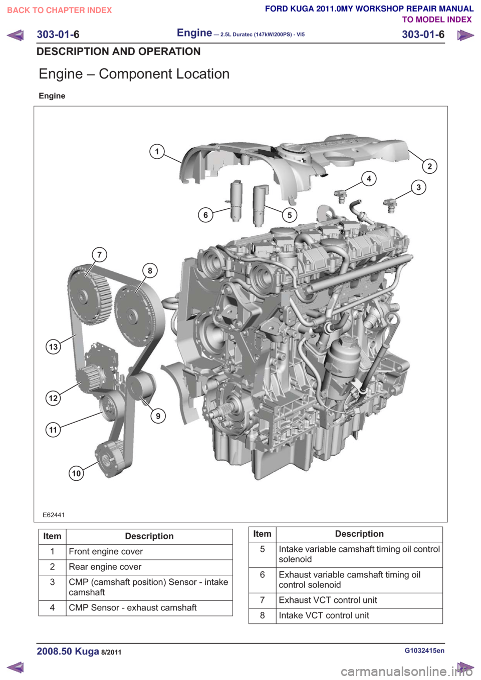
Engine
E62441
1
65
4
3
2
9
10
13
12
11
8
7
Description
Item
Front engine cover
1
Rear engine cover
2
CMP (camshaft position) Sensor - intake
camshaft
3
CMP Sensor - exhaust camshaft
4Description
Item
Intake variable camshaft timing oil control
solenoid
5
Exhaust variable camshaft timing oil
control solenoid
6
Exhaust VCT control unit
7
Intake VCT control unit
8
G1032415en2008.50 Kuga8/2011
303-01- 6
Engine— 2.5L Duratec (147kW/200PS) - VI5303-01-
6
DESCRIPTION AND OPERATION
TO MODEL INDEX
BACK TO CHAPTER INDEX
FORD KUGA 2011.0MY WORKSHOP REPAIR MANUAL
Page 1547 of 2057
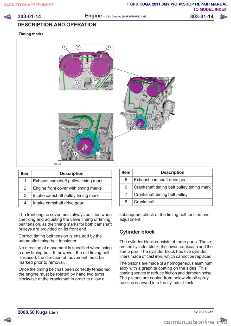
Timing marks
132
45
6
78
E62440
Description
Item
Exhaust camshaft pulley timing mark
1
Engine front cover with timing marks
2
Intake camshaft pulley timing mark
3
Intake camshaft drive gear
4Description
Item
Exhaust camshaft drive gear
5
Crankshaft timing belt pulley timing mark
6
Crankshaft timing belt pulley
7
Crankshaft
8
The front engine cover must always be fitted when
checking and adjusting the valve timing or timing
belt tension, as the timing marks for both camshaft
pulleys are provided on its front end.
Correct timing belt tension is ensured by the
automatic timing belt tensioner.
No direction of movement is specified when using
a new timing belt. If, however, the old timing belt
is reused, the direction of movement must be
marked prior to removal.
Once the timing belt has been correctly tensioned,
the engine must be rotated by hand two turns
clockwise at the crankshaft in order to allow a subsequent check of the timing belt tension and
adjustment.
Cylinder block
The cylinder block consists of three parts. These
are the cylinder block, the lower crankcase and the
sump pan. The cylinder block has five cylinder
liners made of cast iron, which cannot be replaced.
The pistons are made of a homogeneous aluminum
alloy with a graphite coating on the sides. This
coating serves to reduce friction and dampen noise.
The pistons are cooled from below via oil-spray
nozzles screwed into the cylinder block.
G1092773en2008.50 Kuga8/2011
303-01-
14
Engine— 2.5L Duratec (147kW/200PS) - VI5303-01-
14
DESCRIPTION AND OPERATION
TO MODEL INDEX
BACK TO CHAPTER INDEX
FORD KUGA 2011.0MY WORKSHOP REPAIR MANUAL
Page 1555 of 2057
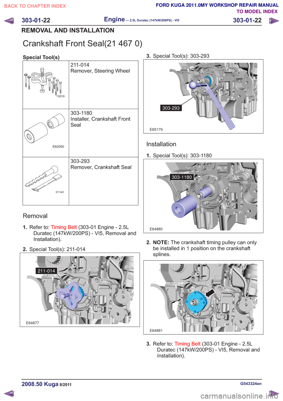
Crankshaft Front Seal(21 467 0)
Special Tool(s)211-014
Remover, Steering Wheel
13019
303-1180
Installer, Crankshaft Front
Seal
E62050
303-293
Remover, Crankshaft Seal
21143
Removal
1.Refer to: Timing Belt (303-01 Engine - 2.5L
Duratec (147kW/200PS) - VI5, Removal and
Installation).
2. Special Tool(s): 211-014
E64877
211-014
3.Special Tool(s): 303-293
E65179
303-293
Installation
1.Special Tool(s): 303-1180
E64880
303-1180
2. NOTE: The crankshaft timing pulley can only
be installed in 1 position on the crankshaft
splines.
E64881
3. Refer to: Timing Belt (303-01 Engine - 2.5L
Duratec (147kW/200PS) - VI5, Removal and
Installation).
G543324en2008.50 Kuga8/2011
303-01- 22
Engine— 2.5L Duratec (147kW/200PS) - VI5303-01-
22
REMOVAL AND INSTALLATION
TO MODEL INDEX
BACK TO CHAPTER INDEX
FORD KUGA 2011.0MY WORKSHOP REPAIR MANUAL
Page 1569 of 2057
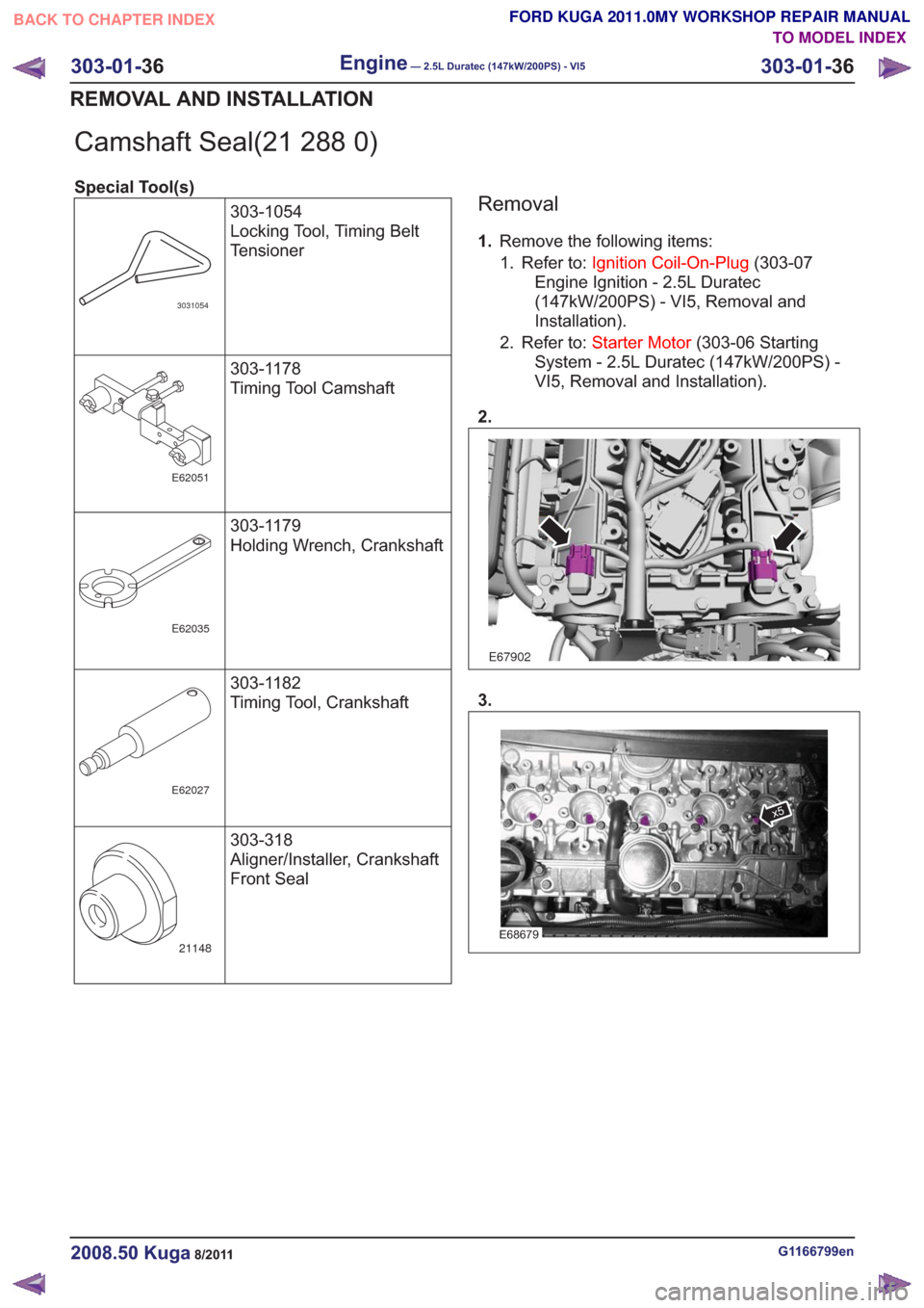
Camshaft Seal(21 288 0)
Special Tool(s)303-1054
Locking Tool, Timing Belt
Tensioner
3031054
303-1178
Timing Tool Camshaft
E62051
303-1179
Holding Wrench, Crankshaft
E62035
303-1182
Timing Tool, Crankshaft
E62027
303-318
Aligner/Installer, Crankshaft
Front Seal
21148
Removal
1.Remove the following items:
1. Refer to: Ignition Coil-On-Plug (303-07
Engine Ignition - 2.5L Duratec
(147kW/200PS) - VI5, Removal and
Installation).
2. Refer to: Starter Motor (303-06 Starting
System - 2.5L Duratec (147kW/200PS) -
VI5, Removal and Installation).
2.
E67902
3.
E68679
x5
G1166799en2008.50 Kuga8/2011
303-01- 36
Engine— 2.5L Duratec (147kW/200PS) - VI5303-01-
36
REMOVAL AND INSTALLATION
TO MODEL INDEX
BACK TO CHAPTER INDEX
FORD KUGA 2011.0MY WORKSHOP REPAIR MANUAL
Page 1581 of 2057
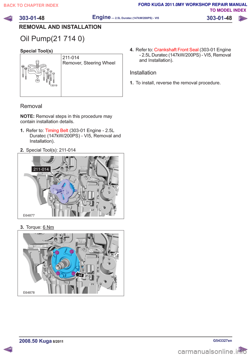
Oil Pump(21 714 0)
Special Tool(s)211-014
Remover, Steering Wheel
13019
Removal
NOTE:Removal steps in this procedure may
contain installation details.
1. Refer to: Timing Belt (303-01 Engine - 2.5L
Duratec (147kW/200PS) - VI5, Removal and
Installation).
2. Special Tool(s): 211-014
E64877
211-014
3.Torque: 6Nm
E64878
4.Refer to: Crankshaft Front Seal (303-01 Engine
- 2.5L Duratec (147kW/200PS) - VI5, Removal
and Installation).
Installation
1. To install, reverse the removal procedure.
G543327en2008.50 Kuga8/2011
303-01- 48
Engine— 2.5L Duratec (147kW/200PS) - VI5303-01-
48
REMOVAL AND INSTALLATION
TO MODEL INDEX
BACK TO CHAPTER INDEX
FORD KUGA 2011.0MY WORKSHOP REPAIR MANUAL