Page 1357 of 2057

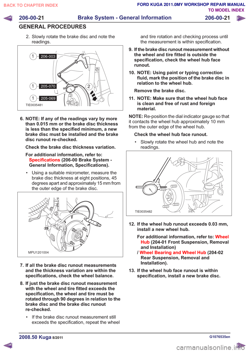
2. Slowly rotate the brake disc and note thereadings.
TIE0035481
2
206-0031
205-0701
205-0691
6. NOTE: If any of the readings vary by morethan 0.015 mm or the brake disc thickness
is less than the specified minimum, a new
brake disc must be installed and the brake
disc runout re-checked.
Check the brake disc thickness variation.
For additional information, refer to:Specifications (206-00 Brake System -
General Information, Specifications).
• Using a suitable micrometer, measure the brake disc thickness at eight positions, 45
degrees apart and approximately 15 mm from
the outer edge of the brake disc.
MPU1201004
7. If all the brake disc runout measurementsand the thickness variation are within the
specifications, check the wheel balance.
8. If just the brake disc runout measurement with the wheel and tire fitted exceeds the
specification, the wheel and tire must be
rotated through 90 degrees in relation to the
brake disc and the brake disc runout
re-checked.
• If the brake disc runout measurement still exceeds the specification, repeat the wheel and tire rotation and checking process until
the measurement is within specification.
9. If the brake disc runout measurement without the wheel and tire fitted is outside the
specification, check the wheel hub face
runout.
10. NOTE: Using paint or typing correction fluid, mark the position of the brake disc in
relation to the wheel hub.
Remove the brake disc.
11. NOTE: Make sure that the wheel hub face is clean and free of rust and foreign
material.
NOTE: Re-position the dial indicator gauge so that
it contacts the wheel hub approximately 10 mm
from the outer edge of the wheel hub.
Check the wheel hub face runout.• Slowly rotate the wheel hub and note the readings.
TIE0035482
12. If the wheel hub runout exceeds 0.03 mm, install a new wheel hub.
For additional information, refer to: Wheel
Hub (204-01 Front Suspension, Removal
and Installation)
/ Wheel Bearing and Wheel Hub (204-02
Rear Suspension, Removal and
Installation).
13. If the wheel hub face runout is within specification, install a new brake disc.
G1076535en2008.50 Kuga8/2011
206-00- 21
Brake System - General Information
206-00- 21
GENERAL PROCEDURES
TO MODEL INDEX
BACK TO CHAPTER INDEX
FORD KUGA 2011.0MY WORKSHOP REPAIR MANUAL
Page 1373 of 2057
SECTION 206-03 Front Disc Brake
VEHICLE APPLICATION:2008.50 Kuga
PA G E
CONTENTS
REMOVAL AND INSTALLATION
206-03-2
(12 234 0)
Brake Pads ........................................................................\
.............................
206-03-4
(12 243 0)
Brake Caliper ........................................................................\
..........................
206-03-5
Front Brake Flexible Hose ........................................................................\
..........................
206-03-1
Front Disc Brake
206-03- 1
.
TO MODEL INDEX
BACK TO CHAPTER INDEX
FORD KUGA 2011.0MY WORKSHOP REPAIR MANUAL
Page 1374 of 2057
Brake Pads(12 234 0)
Special Tool(s)206-005
Retractor, Brake Caliper
Piston
12014
Materials
Specification
Name
WSS-M6C57-A2
Brake Fluid - Super
DOT4
WSS-M12A4-A2 / 1C1J-
19584-BA
Lubricating Paste
Removal
NOTE:
Removal steps in this procedure may
contain installation details.
1. Refer to: Brake System Health and Safety
Precautions (100-00 General Information,
Description and Operation).
2. Refer to: Wheel and Tire (204-04 Wheels and
Tires, Removal and Installation).
3.
E100314
4. WARNING: The brake caliper housing Torx bolts must not be removed.
CAUTION: Make sure that no load is
placed on the brake hose.
Torque: 28
Nm
E94825
12
3
5.
E100312
6.
E100313
G1001203en2008.50 Kuga8/2011
206-03- 2
Front Disc Brake
206-03- 2
REMOVAL AND INSTALLATION
TO MODEL INDEX
BACK TO CHAPTER INDEX
FORD KUGA 2011.0MY WORKSHOP REPAIR MANUAL
Page 1375 of 2057
7.Special Tool(s): 206-005
E94902
206-005
Installation
1. NOTE:
Material: Lubricating Paste (WSS-M12A4-A2 /1C1J-19584-BA) grease
E117895
12
2. Material: Lubricating Paste (WSS-M12A4-A2 /
1C1J-19584-BA) grease
E117451
3. To install, reverse the removal procedure. 4.Depress the brake pedal, check the brake fluid
level in the brake fluid reservoir and top up as
necessary with brake fluid.
Material: Brake Fluid - Super DOT4
(WSS-M6C57-A2) brake fluid
G1001203en2008.50 Kuga8/2011
206-03- 3
Front Disc Brake
206-03- 3
REMOVAL AND INSTALLATION
TO MODEL INDEX
BACK TO CHAPTER INDEX
FORD KUGA 2011.0MY WORKSHOP REPAIR MANUAL
Page 1376 of 2057

Brake Caliper(12 243 0)
General EquipmentHose Clamp(s)
Removal
NOTE: Removal steps in this procedure may
contain installation details.
1. Refer to: Brake System Health and Safety
Precautions (100-00 General Information,
Description and Operation).
2. Refer to: Wheel and Tire (204-04 Wheels and
Tires, Removal and Installation).
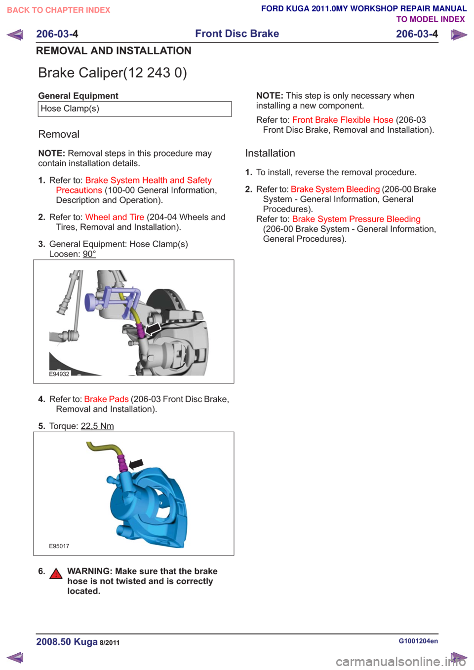
3. General Equipment: Hose Clamp(s)
Loosen: 90°
E94932
4.Refer to: Brake Pads (206-03 Front Disc Brake,
Removal and Installation).
5. Torque: 22,5
Nm
E95017
6. WARNING: Make sure that the brake
hose is not twisted and is correctly
located.
NOTE: This step is only necessary when
installing a new component.
Refer to: Front Brake Flexible Hose (206-03
Front Disc Brake, Removal and Installation).
Installation
1. To install, reverse the removal procedure.
2. Refer to: Brake System Bleeding (206-00 Brake
System - General Information, General
Procedures).
Refer to: Brake System Pressure Bleeding
(206-00 Brake System - General Information,
General Procedures).
G1001204en2008.50 Kuga8/2011
206-03- 4
Front Disc Brake
206-03- 4
REMOVAL AND INSTALLATION
TO MODEL INDEX
BACK TO CHAPTER INDEX
FORD KUGA 2011.0MY WORKSHOP REPAIR MANUAL
Page 1377 of 2057
Front Brake Flexible Hose
Removal
CAUTION:
Refer to:Brake System Health and Safety
Precautions (100-00 General Information,
Description and Operation).
NOTE: Removal steps in this procedure may
contain installation details. 1.
Refer to: Wheel and Tire (204-04 Wheels and
Tires, Removal and Installation).
2. WARNINGS:
Make sure that no load is placed on the
brake hose.
Be prepared to collect escaping fluid.
CAUTION: Make sure that all openings
are sealed.
1. Torque: 15
Nm
4. Torque: 23Nm
E99419
1
2
3
4
Installation
1. To install, reverse the removal procedure.
2. Refer to: Component Bleeding (206-00 Brake
System - General Information, General
Procedures).
G1001206en2008.50 Kuga8/2011
206-03- 5
Front Disc Brake
206-03- 5
REMOVAL AND INSTALLATION
TO MODEL INDEX
BACK TO CHAPTER INDEX
FORD KUGA 2011.0MY WORKSHOP REPAIR MANUAL
Page 1390 of 2057
DETAILS/RESULTS/ACTIONS
TEST CONDITIONS
B2: CHECK PARKING BRAKE CABLES
1 Loosen the parking brake cable tension.
– Rotate the rear wheels by hand.
• Did the rear wheels turn freely?
zYe s INSTALL a new parking brake control.
REFER to: Parking Brake Control (206-05
Parking Brake and Actuation, Removal and
Installation).
TEST the system for normal operation.
zNo
GO to B3.
B3: CHECK FRONT PARKING BRAKE CABLE
1 Disconnect the parking brake front cable and
conduit from the rear brake cable and conduit
at the equalizer.
– Rotate the rear wheels by hand.
• Did the rear wheels turn freely?
zYe s INSTALL a new front parking brake cable and
conduit.
REFER to: Parking Brake Rear Cables (206-
05 Parking Brake and Actuation, Removal
and Installation).
TEST the system for normal operation.
zNo
GO to B4.
G1063696en2008.50 Kuga8/2011
206-05- 7
Parking Brake and Actuation
206-05- 7
DIAGNOSIS AND TESTING
TO MODEL INDEX
BACK TO CHAPTER INDEX
FORD KUGA 2011.0MY WORKSHOP REPAIR MANUAL
Page 1419 of 2057

SECTION 206-09B Anti-Lock Control - Stability Assist
VEHICLE APPLICATION:2008.50 Kuga
PA G E
CONTENTS
DESCRIPTION AND OPERATION
206-09B-2
Anti-Lock Control - Stability Assist (Component Location) .................................................
206-09B-3
Anti-Lock Control - Stability Assist (Overview) ...................................................................
206-09B-3
Overview ........................................................................\
.....................................................
206-09B-4
Testing the brakes on a roller dynamometer - 4X4 vehicles only ...................................
206-09B-4
ABS/ESP module or hydraulic control unit (HCU) ..............................................................
206-09B-4
Combined yaw rate sensor and lateral acceleration sensor / longitudinal acceleration
sensor ........................................................................\
.......................................................
206-09B-5
Front wheel sensor ........................................................................\
.....................................
206-09B-5
Rear wheel sensor ........................................................................\
......................................
206-09B-5
Opto-electronic steering wheel rotation sensor ..................................................................
206-09B-6
ESP switch ........................................................................\
.................................................
206-09B-7
Anti-Lock Control - Stability Assist (System Operation and Component Description) ........
206-09B-7
System Diagram ........................................................................\
.........................................
206-09B-8
System Operation ........................................................................\
.......................................
206-09B-9
PRINCIPLES OF OPERATION ........................................................................\
...............
206-09B-11
Component Description ........................................................................\
..............................
206-09B-?
Opto-electronic steering wheel rotation sensor ..............................................................
206-09B-?
ABS/ESP module or hydraulic control unit (HCU) ..........................................................
206-09B-?
ESP switch ........................................................................\
..............................................
206-09B-?
Combined yaw rate sensor and lateral acceleration sensor / longitudinal acceleration
sensor........................................................................\
................................................... 206-09B-?
Front wheel sensor ........................................................................\
.................................
206-09B-?
Rear wheel sensor ........................................................................\
..................................
REMOVAL AND INSTALLATION 206-09B-16
Hydraulic Control Unit (HCU) ........................................................................\
.....................
206-09B-19
Stability Assist Module ........................................................................\
................................
206-09B-21
Front Wheel Speed Sensor ........................................................................\
........................
206-09B-22
Rear Wheel Speed Sensor ........................................................................\
.........................
206-09B-23
Yaw Rate Sensor ........................................................................\
........................................
206-09B-1
Anti-Lock Control - Stability Assist
206-09B- 1
.
TO MODEL INDEX
BACK TO CHAPTER INDEX
FORD KUGA 2011.0MY WORKSHOP REPAIR MANUAL