Page 17 of 207
 Columbus Navigation System Manual Instruments and warning lights
16
Instruments and warning lightsOverview of the instrument cluster
Engine revolutions counter page 16
Coolant temperature gauge page 16
Fuel gauge page 17
S")
Instruments and warning lights
16
Instruments and warning lightsOverview of the instrument cluster
Engine revolutions counter page 16
Coolant temperature gauge page 16
Fuel gauge page 17
Speedometer page 17
Digital clock, Multi-functional indicator* page 19
Information display* page 22
Clock-set button page 19
Reset button page 17
Odometer and trip counter, service interval display page 18
When the lights are switched on, the instrument cluster is illuminated.
Engine revolutions counterThe start of the red zone in the revolutions counter fig. 18 indicates the
maximum permissible engine speed for all ge ars for an engine which has been run in and operating at a normal temperature. Before
reaching this zone shift up into the next
higher gear.
One should shift to a lower gear at the late st when the engine is no longer running
“smoothly”.
Avoid high engine speeds wh en running-in the vehicle page 128.
For the sake of the environment
Shifting up early helps you save fuel and reduce the operating noise of your vehicle.Coolant temperature gaugeThe coolant temperature gauge fig. 18 operates only when the ignition is
switched on.
In order to avoid any damage to the engine, please pay attention to the following notes
regarding the temperature ranges:
Fig. 18 Instrument cluster
A1A2A3A4A5A6A7A8A9
A1
A2
s2rc.book Page 16 Thursd ay, April 22, 2010 10:58 AM
Page 18 of 207
 Columbus Navigation System Manual Instruments and warning lights17
Using the system
Safety
Driving Tips
General Maintenance
Breakdown assistance
Technical Data
Cold range
If the pointer is in the left-hand area of the scale it means t")
Instruments and warning lights17
Using the system
Safety
Driving Tips
General Maintenance
Breakdown assistance
Technical Data
Cold range
If the pointer is in the left-hand area of the scale it means that the engine has not yet
reached its operating temperature. Avoid running at high engine speeds, at full throttle
and at severe engine loads.
The operating range
The engine has reached its operating temper
ature as soon as the pointer moves into
the mid-range of the scale. The pointer may also move further to the right at high
engine loads and high outside temperatures. This is not critical provided the warning
symbol
in the instrument cluster does not flash.
If the symbol in the instrument cluster flashes it means that either the coolant
temperature is too high or the coolant level is too low. Observe the guidelines
page 28, “Coolant temperature/coolant level ”.
WARNING
Pay attention to the warning notes page 148, “Working in the engine
compartment” before opening the bonnet and inspecting the coolant level.
Caution
Additional headlights and other attached co mponents in front of the fresh air inlet
impair the cooling efficiency of the coolant. There is then a risk of the engine over-
heating at high outside temper atures and high engine loads!Fuel gaugeThe fuel gauge page 16, fig. 18 only operates when the ignition is switched on.
The fuel tank has a capacity of about 55 litres. The warning symbol
in the instrument
cluster lights up when the pointer reaches the reserve marking. There are now about 7
litres of fuel remaining in the tank. This symbol is a reminder for you, that you must
refuel .
The following will be displayed in the information display*: PLEASE REFUEL
A peep sounds as an additional warning signal.
Caution
Never run the fuel tank completely empty! An irregular fuel supply can result in poor
ignition or misfiring. Unburnt fuel may get into the exhaust system and damage the
catalytic converter.SpeedometerWarning against excessive speeds*
An acoustic warning signal will sound when the vehicle speed exceeds 120 kilometres
per hour. The acoustic warning signal will switch off again when the vehicle speed goes
below this speed limit.
Note
This function is only valid for some countries.Counter for distance drivenThe distance which you have driven with your vehicle is shown in kilometres (km). On
certain model versions, the readout is shown in “miles”.
A3
Fig. 19 Instrument cluster:
Counter for distance driven
s2rc.book Page 17 Thursd ay, April 22, 2010 10:58 AM
Page 19 of 207
 Columbus Navigation System Manual Instruments and warning lights
18
Bottom (trip) counter for distance driven
The bottom counter indicates the distance which you have driven since it was last reset
- in steps of 100 m or 1/10 of a mi")
Instruments and warning lights
18
Bottom (trip) counter for distance driven
The bottom counter indicates the distance which you have driven since it was last reset
- in steps of 100 m or 1/10 of a mile. The bo ttom counter can be reset by pressing the
reset button of the trip counter page 17, fig. 19 .
Top counter for distance driven
The top counter indicates the total distance driven in kilometres or miles which the
vehicle has been driven.
Fa u l t d i s p l a y
dEF appears permanently in the trip counter display for distance driven if there is a
fault in the instrument cluster. Have the fault rectified as soon as possible by a
specialist workshop.
WARNING
Never seek to adjust the trip counter for distance driven while driving for safety
reasons!Service Interval DisplayDepending on the equipment installed in the vehicle, the text can differ slightly on the
display. Service Interval Display
If the due date for the service is reached, it is displayed
1):
in the display of the trip counter: Service 1 500 km
in the information display: SERVICE in 1500 km
The kilometre readout decreases in steps of 100°km.
If the due date for the service is reached, the following text appears as a flashing
display:
in the display of the trip counter:
Service
in the information display: SERVICE NOW
The display disappears within 20 seconds af ter switching on the ignition. The trip
counter is also displayed after pressing the reset button for the trip counter (for more
than 0.5 second).
Resetting Service Interval Display
It is only possible to reset the Service Interval Display, if a service message or at least a
pre-warning is shown on the disp lay of the instrument cluster.
We recommend having this resetting performed by a specialist garage.
The specialist garage:
resets the memory of the display after the appropriate inspection;
makes an entry in the Service schedule;
affix the sticker with the entry of the following service interval to the side of the
dash panel on the driver's side.
The service interval display can also be reset with the reset button as follows
page 16, fig. 18 :
Fig. 20 Service Interval Display:
Note
1)On some vehicles, the service interval display service OIL or service INSP is shown.
A8
s2rc.book Page 18 Thursd ay, April 22, 2010 10:58 AM
Page 20 of 207
 Columbus Navigation System Manual Instruments and warning lights19
Using the system
Safety
Driving Tips
General Maintenance
Breakdown assistance
Technical Data
Press the reset button with the ignition switched off and and hold it")
Instruments and warning lights19
Using the system
Safety
Driving Tips
General Maintenance
Breakdown assistance
Technical Data
Press the reset button with the ignition switched off and and hold it down.
Switch the ignition on, release the reset button. The text Service or SERVICE NOW
appears in the display.
Turn the button for setting the clock to the right - as a result of this the display is
reset.Caution
We recommend that you do not reset the Se rvice Interval Display yourself otherwise
this can result in the service interval display being incorrectly set, which may also result
in problems with operation of your vehicle.
Note
Never reset the display between service intervals otherwise this may result in
incorrect readouts.
information is retained in the Service Interval Display also after the battery of the
vehicle is disconnected.
It is necessary to re-code the Service Interval Display if a new instrument cluster is
installed during repair work. This work is carried out by a specialist garage.
The data displayed is the same after resetting the display with flexible service inter-
vals (QG1) using the reset button as that for a vehicle with fixed service intervals (QG2).
We therefore recommend having the Service In terval Display reset only by a specialist
garage which is familiar with the procedure for resetting the display with a vehicle
system tester.
Please refer to the brochure Service schedule for extensive information about the
service intervals.
Digital clockA clock-set button is installed on the bottom left beside the speedometer for
adjusting the clock page 16, fig. 18.Set hours– Turn the reset button to the left.
Setting minutes– Turn the reset button to the right.
WARNING
The clock should not be adjusted while driving for safety reasons but only when
the vehicle is stationary!Multi-functional indica tor (onboard computer)*IntroductionThe multi-functional indicator appears in th e display of the revolutions counter or in
the information display depending on th e equipment fitted to your vehicle page 22,
fig. 22 .
The multi-functional indicator offers you a range of useful information.
Note
In certain national versions the displays a ppear in the Imperial system of measures.MemoryThe multi-functional indicator is equipped with two automatic memories.
A7
The outside temperature
page 20
Current fuel consumption
page 21
Average fuel consumption
page 21
Range
page 21
Distance driven
page 21
Average speed
page 21
Driving time
page 21
Time
s2rc.book Page 19 Thursd ay, April 22, 2010 10:58 AM
Page 21 of 207
 Columbus Navigation System Manual Instruments and warning lights
20
The data of the single-trip memory (memory 1) is shown if a 1 appears in the display.
A 2 shown in the display means that data relates to the total distance memory")
Instruments and warning lights
20
The data of the single-trip memory (memory 1) is shown if a 1 appears in the display.
A 2 shown in the display means that data relates to the total distance memory
(memory 2).
Switching over the memory takes place with the button fig. 21 .
Single-trip memory (memory 1)
The single-trip memory collates the driving information from the moment the ignition
is switched on until it is switched off. New data will also flow into the calculation of the
current driving information if the trip is continued within 2 hours after switching off
the ignition. The memory will be is automatically erased, on the other hand, if the trip
is interrupted for more than 2 hours .
Total-trip memory (memory 2)
The total distance driven memory gathers data from any number of individual jour-
neys up to a total of 99 hours and 59 minut es driving or 9.999 kilometres driven. The
memory is deleted when either of these li mits is reached and the calculation starts
from anew.
The total-trip memory will not, contrary to the single-trip memory, be deleted after a
period of interr uption of driving of 2 hours.
Note
All information in the memory is erased if the battery of the vehicle is disconnected.Using the system
The rocker switch and the button are located on the windshield wiper lever
fig. 21 .Selecting the memory– Repeated short-term pressing of the button allows to select the desired
memory.Selecting the functions– Press the rocker switch up or down. Th is will cause the individual functions of
the multi-functional indicator to appear in the display one after the other.Setting function to zero– Select the memory you want.
– Press button for more than 1 second.
The following readouts of the selected me mory will be set to zero by button :
average fuel consumption,
distance driven,
average speed,
Driving time.
You can only operate the multi-functional in dicator when the ignition is switched on.
After the ignition is switched on, the function displayed is the one which you last
selected before switch ing off the ignition.
If the outside temperature drops below +4 °C, the outside temperature indicator with
a snow flake symbol appears. The symbol warns the driver of the possible danger of
ice on the road. After the rocker switch is pressed, the function displays the one
which you last selected before switching off the ignition.
Outside temperatureThe outside temperature appears in the display when the ignition is switched on.
The correct outside temperature will be indicated with a delay of 5 minutes. If the
vehicle is stationary (or driven at a very low speed) the temperature indicated may be
ABFig. 21 Multi-functional indi-
cator: Control elements
AA
AB
AB
AA
AB
AB
AA
s2rc.book Page 20 Thursd ay, April 22, 2010 10:58 AM
Page 22 of 207
 Columbus Navigation System Manual Instruments and warning lights21
Using the system
Safety
Driving Tips
General Maintenance
Breakdown assistance
Technical Data
slightly higher than the actual outside te
mperature because of heat radia")
Instruments and warning lights21
Using the system
Safety
Driving Tips
General Maintenance
Breakdown assistance
Technical Data
slightly higher than the actual outside te
mperature because of heat radiated by the
engine.
If the outside temperature drops below +4°C, a snow flake symbol (warning signal for
ice on the road) appears behind the temperature indicator and a warning signal
sounds.
WARNING
Do not only rely upon the information given on the outside temperature
display that there is no ice on the road. Please note that black ice may also be
present on the road surface even at temperatures around +4°C - warning, drive
with care!Current consumptionThe current fuel consumption level is shown in the display in litres/100 km. This infor-
mation can help you to adapt your style of driving to the fuel consumption you wish to
achieve.
The display appears in litres/hour if the vehicle is stationary or driving at a low speed.Average fuel consumptionThe average fuel consumption since the memory was last erased is shown in the
display in litres/100 km page 19. This information can he lp you to adapt your style
of driving to the fuel consumption you wish to achieve.
If you wish to determine the average fuel consumption over a cert ain period of time
you must first erase the memory at the start of the new measurement using the button
page 20, fig. 21 . A zero appears in the display for the first 300 m you drive after
erasing the memory.
The indicated value will be updated every 5 seconds while you are driving.
Note
The amount of fuel consum ed will not be indicated.
RangeThe estimated range in kilometres is shown on the display. It indicates the distance you
can still drive with your vehicle based on th e present level of fuel in the tank for the
same style of driving. The readout is shown in steps of 10 km.
The fuel consumption for the last 50 km is ta ken as a basis for calculating the range. If
you drive in a more economical manner from this moment on, the range will be
increased accordingly.
You first drive 50 km if the readout is reset (after disconnecting the battery) before a
new readout for the range is displayed.Distance drivenThe distance driven since the memory was last erased appears in the display
page 19. If you wish to calcul ate the distance driven from a particular time of day
you must first erase the memory at this moment in time by pressing the button
page 20, fig. 21 .
The maximum distance indicated in both memories is 9 999 km. The indicator is set
back to null if this period is exceeded.Average speedThe average speed since the memory was last erased is shown in the display in
km/hour page 19. If you wish to determine the average speed over a certain period
of time you must first erase the memory at the start of the new measurement using the
button page 20, fig. 21 .
A zero appears in the display for the first 300 m you drive after erasing the memory.
The indicated value will be updated every 5 seconds while you are driving.Driving timeThe driving time which has elapsed since the memory was last erased, appears in the
display page 19. If you wish to calculate the dr iving time from a particular time of
day you must first erase the memory at this moment in time by pressing the button
page 20, fig. 21 .
AB
AB
AB
AB
s2rc.book Page 21 Thursd ay, April 22, 2010 10:58 AM
Page 23 of 207
 Columbus Navigation System Manual Instruments and warning lights
22
The maximum distance indicated in both memories is 99 hours and 59 minutes. The
indicator is set back to null if this period is exceeded.Warning against excessive")
Instruments and warning lights
22
The maximum distance indicated in both memories is 99 hours and 59 minutes. The
indicator is set back to null if this period is exceeded.Warning against excessive speeds*An acoustic warning signal will sound when the vehicle speed exceeds 120 kilometres
per hour. The acoustic warning signal will switch off again when the vehicle speed goes
below this speed limit.
This function is only valid for some export countries.Information display*Introduction
The information display provides you with information in a convenient way
concerning the current operating state of your vehicle . The information system also
provides you with data (depending on the equipment installed in the vehicle) relating
to the radio and multi-functional indicator.
Certain functions and operatin g conditions are always being checked on the vehicle
when the ignition is switched on and also while driving.
Functional faults, if required repair work and other information are indicated by red
symbols and yellow symbols.
Lighting up of these symbols is combined with an acoustic warning signal.
Information and text s giving warnings are also shown in the display page 25.
The display of text is possible in the following languages: Czech, English, German, French, Italian, Spanish, Portuguese.
The desired language can be set by a specialist garage.
The following information can be shown in the display (depending on the equipment
installed on the vehicle):
Fig. 22 Instrument cluster: large
information display
Menu
page 23
Door and boot lid warning
page 23
Displays of the multi-functional indicator
page 16
Fig. 23 Instrument cluster: small
information display
s2rc.book Page 22 Thursd ay, April 22, 2010 10:58 AM
Page 24 of 207
 Columbus Navigation System Manual Instruments and warning lights23
Using the system
Safety
Driving Tips
General Maintenance
Breakdown assistance
Technical Data
Menu– You can activate the menu by pressing the rocker switch fig.")
Instruments and warning lights23
Using the system
Safety
Driving Tips
General Maintenance
Breakdown assistance
Technical Data
Menu– You can activate the menu by pressing the rocker switch fig. 25 for more
than 1 second.
– You can select individual menu points by means of the rocker switch . The selected information is displayed after pr essing the button for a short time or
after releasing the rocker swit ch (after about 4 seconds). You can select the following information (d
epending on the equipment installed on
the vehicle):
After selecting the menu point DISPLAY OFF the display is switched off. Press the
rocker switch for more than 1 seco nd to switch the display on again.
The Information CAR STATUSflashes in the menu if there is something which is not in
proper order on the vehicle (e.g. warning of a low fuel level). The first warning will be
displayed after switching over to CAR STATUS. You can then display other operating
conditions afterwards using the switch-o ver function (such as water level low).
Door and boot lid warningThe door and boot lid warning lights up if at least one door or the boot lid is not closed.
The symbol displays the respective opened door and boot lid.
The symbol goes out as soon as the doors and the boot lid are completely closed.
As an additional warning signal, a 3 time peep sounds if the car is driven at a speed of
more than 6km/hour and if the door is open.Auto Check ControlCar stateThe Auto Check Control carries out a chec k of certain functions and vehicle compo-
nents. The check is performed constantly when the ignition is switched on, both when
the vehicle is stationary, as well as when driving.
Operational faults, urgent repairs, service work or other information appear in the
display of the instrument cluster. The disp lays are shown with a red or yellow light
symbol depending on the priority of the message.
Warning symbols or warning lights
page 25
Displays of the Service Interval Display
page 18
Displays of the radio
Fig. 24 Information display:
MenuFig. 25 Information display:
Control elements
AA
AA
AB
AA
TRIP COMPUTER (AUTO COMPUTER)
page 19
CAR STATUS
page 23
DISPLAY OFF
AA
s2rc.book Page 23 Thursd ay, April 22, 2010 10:58 AM
 1
1 2
2 3
3 4
4 5
5 6
6 7
7 8
8 9
9 10
10 11
11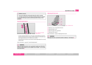 12
12 13
13 14
14 15
15 16
16 17
17 18
18 19
19 20
20 21
21 22
22 23
23 24
24 25
25 26
26 27
27 28
28 29
29 30
30 31
31 32
32 33
33 34
34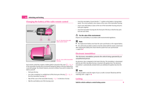 35
35 36
36 37
37 38
38 39
39 40
40 41
41 42
42 43
43 44
44 45
45 46
46 47
47 48
48 49
49 50
50 51
51 52
52 53
53 54
54 55
55 56
56 57
57 58
58 59
59 60
60 61
61 62
62 63
63 64
64 65
65 66
66 67
67 68
68 69
69 70
70 71
71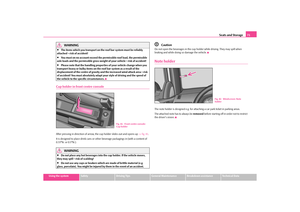 72
72 73
73 74
74 75
75 76
76 77
77 78
78 79
79 80
80 81
81 82
82 83
83 84
84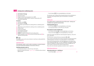 85
85 86
86 87
87 88
88 89
89 90
90 91
91 92
92 93
93 94
94 95
95 96
96 97
97 98
98 99
99 100
100 101
101 102
102 103
103 104
104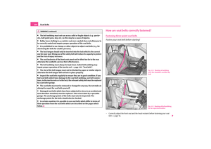 105
105 106
106 107
107 108
108 109
109 110
110 111
111 112
112 113
113 114
114 115
115 116
116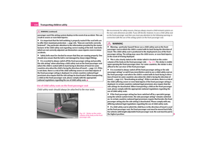 117
117 118
118 119
119 120
120 121
121 122
122 123
123 124
124 125
125 126
126 127
127 128
128 129
129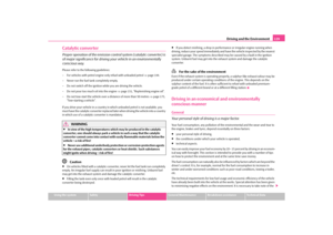 130
130 131
131 132
132 133
133 134
134 135
135 136
136 137
137 138
138 139
139 140
140 141
141 142
142 143
143 144
144 145
145 146
146 147
147 148
148 149
149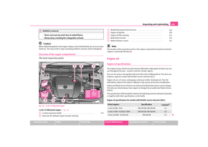 150
150 151
151 152
152 153
153 154
154 155
155 156
156 157
157 158
158 159
159 160
160 161
161 162
162 163
163 164
164 165
165 166
166 167
167 168
168 169
169 170
170 171
171 172
172 173
173 174
174 175
175 176
176 177
177 178
178 179
179 180
180 181
181 182
182 183
183 184
184 185
185 186
186 187
187 188
188 189
189 190
190 191
191 192
192 193
193 194
194 195
195 196
196 197
197 198
198 199
199 200
200 201
201 202
202 203
203 204
204 205
205 206
206