2010 SKODA OCTAVIA TOUR Columbus Navigation System Manual
-
 1
1 -
 2
2 -
 3
3 -
 4
4 -
 5
5 -
 6
6 -
 7
7 -
 8
8 -
 9
9 -
 10
10 -
 11
11 -
 12
12 -
 13
13 -
 14
14 -
 15
15 -
 16
16 -
 17
17 -
 18
18 -
 19
19 -
 20
20 -
 21
21 -
 22
22 -
 23
23 -
 24
24 -
 25
25 -
 26
26 -
 27
27 -
 28
28 -
 29
29 -
 30
30 -
 31
31 -
 32
32 -
 33
33 -
 34
34 -
 35
35 -
 36
36 -
 37
37 -
 38
38 -
 39
39 -
 40
40 -
 41
41 -
 42
42 -
 43
43 -
 44
44 -
 45
45 -
 46
46 -
 47
47 -
 48
48 -
 49
49 -
 50
50 -
 51
51 -
 52
52 -
 53
53 -
 54
54 -
 55
55 -
 56
56 -
 57
57 -
 58
58 -
 59
59 -
 60
60 -
 61
61 -
 62
62 -
 63
63 -
 64
64 -
 65
65 -
 66
66 -
 67
67 -
 68
68 -
 69
69 -
 70
70 -
 71
71 -
 72
72 -
 73
73 -
 74
74 -
 75
75 -
 76
76 -
 77
77 -
 78
78 -
 79
79 -
 80
80 -
 81
81 -
 82
82 -
 83
83 -
 84
84 -
 85
85 -
 86
86 -
 87
87 -
 88
88 -
 89
89 -
 90
90 -
 91
91 -
 92
92 -
 93
93 -
 94
94 -
 95
95 -
 96
96 -
 97
97 -
 98
98 -
 99
99 -
 100
100 -
 101
101 -
 102
102 -
 103
103 -
 104
104 -
 105
105 -
 106
106 -
 107
107 -
 108
108 -
 109
109 -
 110
110 -
 111
111 -
 112
112 -
 113
113 -
 114
114 -
 115
115 -
 116
116 -
 117
117 -
 118
118 -
 119
119 -
 120
120 -
 121
121 -
 122
122 -
 123
123 -
 124
124 -
 125
125 -
 126
126 -
 127
127 -
 128
128 -
 129
129 -
 130
130 -
 131
131 -
 132
132 -
 133
133 -
 134
134 -
 135
135 -
 136
136 -
 137
137 -
 138
138 -
 139
139 -
 140
140 -
 141
141 -
 142
142 -
 143
143 -
 144
144 -
 145
145 -
 146
146 -
 147
147 -
 148
148 -
 149
149 -
 150
150 -
 151
151 -
 152
152 -
 153
153 -
 154
154 -
 155
155 -
 156
156 -
 157
157 -
 158
158 -
 159
159 -
 160
160 -
 161
161 -
 162
162 -
 163
163 -
 164
164 -
 165
165 -
 166
166 -
 167
167 -
 168
168 -
 169
169 -
 170
170 -
 171
171 -
 172
172 -
 173
173 -
 174
174 -
 175
175 -
 176
176 -
 177
177 -
 178
178 -
 179
179 -
 180
180 -
 181
181 -
 182
182 -
 183
183 -
 184
184 -
 185
185 -
 186
186 -
 187
187 -
 188
188 -
 189
189 -
 190
190 -
 191
191 -
 192
192 -
 193
193 -
 194
194 -
 195
195 -
 196
196 -
 197
197 -
 198
198 -
 199
199 -
 200
200 -
 201
201 -
 202
202 -
 203
203 -
 204
204 -
 205
205 -
 206
206
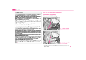
 Columbus Navigation System Manual Cockpit
8Fig. 1 Certain items of equipment shown in the illustration are only fitted to partic ular model versions or are optional items of equipment.s2rc.book Page 8 Thursday, April 22, 2010 10:5")
 Columbus Navigation System Manual Cockpit9
Using the system
Safety
Driving Tips
General Maintenance
Breakdown assistance
Technical Data
CockpitOverviewThis overview will help you to quic kly familiarise yourself with the
displays and")
 Columbus Navigation System Manual Quick Reference Guide
10
Quick Reference GuideBasic functions and im portant informationIntroduction
The chapter of the brief instruction is only used as a quick reference of
the most important oper")
 Columbus Navigation System Manual Quick Reference Guide11
Using the system
Safety
Driving Tips
General Maintenance
Breakdown assistance
Technical Data
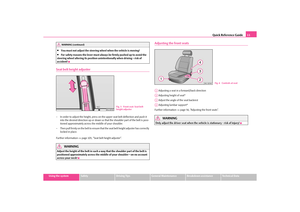
You must not adjust the steering wheel when the vehicle is moving!
For safe")
 Columbus Navigation System Manual Quick Reference Guide
12
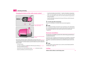
Electric exterior mirror adjustment*Further information page 54, “Exterior mirror”.
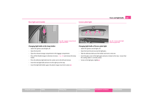
Switching lights on and offFurther information page 46, “Switching lights on")
 Columbus Navigation System Manual Quick Reference Guide13
Using the system
Safety
Driving Tips
General Maintenance
Breakdown assistance
Technical Data
Turn signal light right
Turn signal light left
Switching over between low beam a")
 Columbus Navigation System Manual Quick Reference Guide
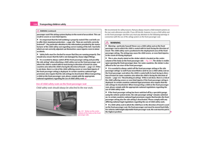
14
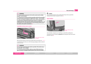
Opening the fuel filler cap
– Open the fuel filler flap with the hand.
– Unlock the fuel filler cap on the fuel fill er tube to the left using the vehicle key.
– Unscrew")
 Columbus Navigation System Manual Quick Reference Guide15
Using the system
Safety
Driving Tips
General Maintenance
Breakdown assistance
Technical Data
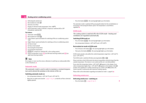
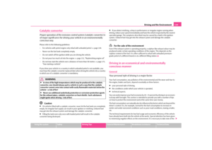
– Grip with the hand under the radiat
or grille and lift up the bonnet.
– Press")