Page 185 of 244

Accessories, changes and replacement of parts
184
Accessories, changes and replacement of partsAccessories and re
placement parts
Škoda vehicles have been built according to
the latest discoveries in safety engi-
neering. Thus one should not change the co
ndition in which the vehicle was delivered
from the manufacturer without some thought. The following guidelines should be observed
when a vehicle is to be retrofitted with
accessories, have technical ch
anges made to it or a part has to be replaced at some
time in the future.
Advise should always be obtained from a specialist garage
before
buying any
accessories and
before
making any technical changes
.
This is particularly the case when acce
ssories are bought in a foreign country.
Škoda Genuine Accessories wh
ich have been released for use and Škoda original
parts can be bought from specialist ga
rages that professionally undertake the
assembly of parts which were purchased there.
All Škoda original accessories which are listed in the catalogue of original accesso-
ries such as spoilers, transport systems, child seats, etc., are homologized.
Radios, aerials and other electrical acce
ssories should only be installed by a
specialist garage.
The guidelines issued by Škoda Auto mu
st be observed when
making technical
changes.
This is to ensure that no technical damage
occurs to the vehicle, that travelling and
operating safety are maintained and that the chnages are permissible. The specialist garages also undertake this work professionally
or refer it to another specialist garage
in special cases. Any damage which is done caused by tech
nical changes made without consulting
a Skoda dealer is exclud
ed from the guarantee.
WARNING
We advise you, in your own interest, to only use Škoda Genuine Accessories
and Škoda original parts which have been
expressly approved for use on your
Škoda. Reliability, safety and suitabilii
ty have been established for these Škoda
original parts.
We cannot guarantee suitability of installation into your vehicle of other
products despite keeping a constant eye
on market developments (also not in
the case where there is an attestation or permission can be produced).Technical changesInterference on the electronic components and their software can lead to operational faults. This interference can also impair no
t directly affected sy
stems because of the
networking of the electronic components. This
means that the operating safety of your
vehicle can be considerably jeopardized, a
greater wear of vehicle parts can occur and
finally the vehicle registration documents expire. We trust that you will understand that Šk
oda Auto cannot be liable for damage
resulting from unprofessional work. We therefore recommend that you have all wo
rk carried out with Škoda original parts
at specialist garages.
WARNING
Work or modifications on your vehicle, which have been carried out unprofes-sionally, can cause operational faults - risk of accident!Vehicles of category N1The vehicle of category N1 is a vehicle wh
ich is designed and manufactured for trans-
porting loads with a maximum weight of 3.5 tonnes.
WARNING (continued)
s3j8.a.book Page 184 Tuesday, April 20, 2010 1:10 PM
Page 186 of 244

Breakdown assistance
185
Using the system
Safety
Driving Tips
General Maintenance
Breakdown assistance
Technical Data
Breakdown assistanceBreakdown assistanceFirst-aid box* and Warning triangle*The first-aid box must be stored in such a
way that it is immediately ready to hand.
A warning triangle with the maximum di
mensions 39 x 68 x 450 mm
can be attached
to the trim panel of the rear wall with rubber straps
fig. 149
.
If you wish to equip your ve
hicle additionally with a warning triangle, please contact a
specialist garage.
WARNING
The first-aid box must be stored in such a way that the occupants do no suffer any injuries in the event of an emergency
braking or a collision of the vehicle.
Note
Pay attention to the use-by-date of the contents of the first-aid box.Fire extinguisher*The fire extinguisher is attached
with straps under the driver seat.
Please read carefully the instructions whic
h are attached to the fire extinguisher.
The fire extinguisher must be checked by
an authorised person or company annually
(please observe the various differing national legal requirements).
WARNING
If the fire extinguisher is
not correctly attached, in
case of sudden manoeuvres
or an accident it can be “thrown” through the interior compartment and cause injuries.
Note
The fire extinguisher must comply with
the relevant and valid legal requirements.
Pay attention to the expiration date of the fire extinguisher. If the fire extinguisher
is used after the expiration date, its
proper function is no longer assured.
The fire extinguisher is only supplied in
certain countries within the scope of
delivery.Vehicle tool kit
Fig. 149 Placing of the warning triangle
Fig. 150 Luggage compartment: storage compartment for vehicle tool kit
s3j8.a.book Page 185 Tuesday, April 20, 2010 1:10 PM
Page 187 of 244

Breakdown assistance
186
The vehicle tool kit and the lifting jack* are
housed in a plastic box in the spare wheel*
page 185, fig. 150
or in the space for the spare wheel. There is also space here for
the removable ball for the trailer towing device. The vehicle tool kit contains the following
parts (depending on equipment fitted):
wheel wrench*;
wire clamps for removing the full wheel trims;
towing eye;
Adapter for the safety wheel bolts*;
Extraction pliers for wheel bolt caps;
Replacement bulb set;
Screwdriver*.
Before placing the lifting jack back in its storage area, screw in the arm of the lifting jack fully.
WARNING
The factory-supplied lifting jack is only intended for your model of vehicle.
On no account attempt to lift a heavier vehicle or other loads - risk of injury!
Ensure that the vehicle tool kit is safely attached in the luggage
compartment.Tyre repair kitThe tyre repair kit is intended for the repair
of minor tyre defects. The tyre repair kit
contains a compressor, inflation bottle,
operating instructions and accessories.
The repair with the tyre repair kit is
not at all intended to replace
a permanent repair
on the tyre; this repair only serves to re
ach a workshop. The repair can be undertaken
on the vehicle immediately.
Please read the attached in
structions carefully before
the repair. The ty re re pa ir kit i s s towed in a n ins er ted foa m pie ce unde r the lugga ge com pa r tment cover or in the right part
of the luggage compartment.
Spare wheel*The spare wheel is stowed in th
e spare wheel well in the luggage
compartment below the floor covering.The spare wheel lies in a well under the floor covering of the luggage compartment and is fixed in place along with a vehicle tool kit box using a special screw
fig. 151
.
One should check the inflation pressure in
the spare wheel (at best when generally
checking the tyre air pressures - see sign on the fuel filler flap
page 163) to ensure
that the spare wheel is always ready to use. Unidirectional tyres* If you have such tyres on your vehi
cle, please refer to the notes below:
The spare wheel provided with a car fitted with unidirectional tyres has different
dimensions. The wheel is provided with a warning sticker.
The warning label must not be covered after installing the wheel.
Do not drive faster than 80 km/h with this spare wheel and pay particular attention
while driving. Avoid accelerating at full throttle, sharp braking and fast cornering.
The inflation pressure for this spare wheel is identical to the inflation pressure of
the standard tyres.
Use this spare wheel only to reach the nearest specialist garage as it is not intended
for continuous use.
Fig. 151 Luggage compartment: Spare wheel
s3j8.a.book Page 186 Tuesday, April 20, 2010 1:10 PM
Page 188 of 244

Breakdown assistance
187
Using the system
Safety
Driving Tips
General Maintenance
Breakdown assistance
Technical Data
Changing a wheelPreliminary workThe following steps should be carried ou
t before actually changing the wheel.
– If it is necessary to change a wheel, park
the vehicle as far aw
ay as possible from
the traffic flow. The place you choose should be
level
.
– Have all the occupants
get out
. While changing a wheel, the occupants of the
vehicle should not stand on the ro
ad (e.g. behind a crash barrier).
– Apply the
handbrake
firmly.
–Engage
1st gear
or if your vehicle is fitted with
an automatic gearbox, position the
selector lever into position P
.
– If a trailer is coupled, uncouple it.– Take the
vehicle tool kit
and the
spare wheel*
page 185 out of the luggage
compartment.
WARNING
If you find yourself in flowing traffic switch on the hazard warning lights
system and place the warning triangle on
the side of the road at the prescribed
distance from your vehicle while observing all national legal provisions. In this way you are protecting not only yourself but also other road users.
Never start the engine with the vehicle si
tting on the raised
jack - danger of
suffering injury.
Caution
If you have to change a wheel on a slope first block the opposite wheel with a stone or similar object in order to secure the
vehicle from unexpectedly rolling away.
Note
Comply with the national legal regulations.
Changing a wheelAlways change a wheel on a level surface as far as possible. – Take off the full wheel trim*
page 188 or the caps
page 188.
– Slacken the wheel bolts
page 189.
– Jack up the vehicle until the wheel to
be changed is clear of the ground
page 189.
– Unscrew the wheel bolts and place them
on a clean surface (cloth, paper etc.).
– Take off the wheel.– Fit on the spare wheel* and tighten the wheel bolts slightly.– Lower the car.– Tighten the wheel bolts firmly, alternatel
y and diagonally using the wrench (cross-
wise)
page 189.
– Mount the full wheel trim/wheel trim cap or the caps.
Note
All bolts must be clean and must turn easily.
You must never grease or oil the wheel bolts!
When fitting on unidirectiona
l tyres, ensure that the tyres rotate in the correct
direction
page 178.
Subsequent stepsAfter changing the wheel, you mu
st perform the following steps.
– Stow the vehicle tool kit in the space provided.– Stow the replaced wheel in the luggage compartment.–
Check
the
tyre pressure
on the spare wheel just mounted as soon as possible.
– Have the
tightening torque
of the wheel bolts
checked
with a torque wrench as
soon as possible. Steel and light alloy wheels must be tightened to a tightening torque of
120 Nm
.
s3j8.a.book Page 187 Tuesday, April 20, 2010 1:10 PM
Page 189 of 244

Breakdown assistance
188
– Change the damaged wheel or consult a specialist garage about possibilities for
getting repairs done.
WARNING
It is necessary to observe the guidelines given on
page 180, “New tyres and
wheels” if the vehicle is subsequently fi
tted with tyres which are different to
those it was fitted with at the works.
Note
If you find, when changing the wheel, that
the wheel bolts are corroded and diffi-
cult to turn, the bolts must be replaced
before checking the tightening torque.
Drive cautiously and only at a moderate speed to a workshop where the tightening
torque can be checked.Full wheel trim*Pulling off– Hook the clamp found in the vehicle tool
kit into the reinforced edge of the full
wheel trim.
– Push the wheel key through the clamp, support the wheel key on the tyre and pull
off the wheel trim
fig. 152
.
Installing– First press the full wheel trim onto the wheel at the valve opening provided. Then
press the full wheel trim into the wheel in
such a way that its entire circumference
locks correctly in place.Caution
Use the pressure of your hand, do not knock on the full wheel trim! Heavy knocks
mainly on the points where the full wheel trim has not been inserted into the wheel, can result in damage to the guide and centering elements of the full wheel trim.
Check for yourself that the safety wheel bolt
is located in the hole in the area of the
valve before fitting the full wheel trim onto a
steel wheel which is attached with a safety
wheel bolt
page 190, “Securing wheels against being stolen*”.
Wheel bolts with caps* The caps are designed to protect the wheel bolts.Pulling off– Insert the
plastic clip
(in the car tool kit) sufficiently
far onto the cap until the inner
catches of the clip are positioned at the collar of the cap.
– Pull the cap off with the
plastic clip
fig. 153
.
Installing– Insert the caps onto the bolts.
Fig. 152 Removing the full wheel trim
Fig. 153 Changing a wheel: Pull off cap from the wheel bolt
s3j8.a.book Page 188 Tuesday, April 20, 2010 1:10 PM
Page 190 of 244

Breakdown assistance
189
Using the system
Safety
Driving Tips
General Maintenance
Breakdown assistance
Technical Data
Slackening and tightening wheel bolts Slacken the wheel bolts befo
re jacking up the vehicle.
Slackening wheel bolts– Insert the wheel wrench fully onto the wheel bolt
13).
– Grasp the end of the wrench and turn the bolt about
one
turn to the left
fig. 154
.
Tightening wheel bolts– Insert the wheel wrench fully onto the wheel bolt
13).
– Grasp the end of the wrench and turn the bolt to the right until it is tight.
WARNING
Slacken the wheel bolts only a little (abo
ut one turn) as long as the vehicle has
not yet been jacked up - risk of an accident!
Note
Apply pressure carefully with your
foot
to the e nd of the wrench if it prove s d iff icult
to slacken the bolts. Hold tight on the vehicl
e when doing this and ensure that you have
a steady position.
Raise vehicle You have to raise the vehicle with a lifting jack in order to be able to take off the wheel.– Position the lifting jack by selecting the ja
cking point - engraving in the lower sill -
which is closest to the wheel to be removed
fig. 155
.
– Position the lifting jack below the jacking
point and move it up until its claw is posi-
tioned directly below the vertical web of the lower sill.
– Align the lifting jack so that its claw grasps the vertical web on the engraving of the
lower sill and the bottom ba
se plate of the lifting jack is resting flat with its
complete surface against firm ground.
– Turn the lifting jack up further until
the wheel is just clear of the ground.
Ground below the lifting jack which is soft and slippery
can cause the vehicle to slip
off the jack. It is therefore always necessary
to place the lifting jack on a solid surface
or use a wide and stable base. Use a non-sl
ip base (e.g. a rubber foot mat) if the
surface is smooth
, such as cobbled stones, a tiled floor, etc.
WARNING
Always raise the vehicle with the doors closed - risk of injury.
Take suitable measures to prevent the ba
se of the lifting jack from slipping
off - risk of injury!
Place the lifting ja
ck only on a soli
d and even surface.
13)Use the appropriate adapter for slackening and tightening the safety wheel bolts
page 190.
Fig. 154 Changing a wheel: Slackening wheel bolts
Fig. 155 Changing a wheel: Jacking points for positioning lifting jack
AA
AB
s3j8.a.book Page 189 Tuesday, April 20, 2010 1:10 PM
Page 191 of 244

Breakdown assistance
190
Not positioning the lifting jack at the specified points can result in damage
to the vehicle. The jack can also slip off if it does not have sufficient grip - risk of injury!
Never start the engine if the vehicle is lifted - risk of accident.
Never lie under the vehicle if the vehicle is only lifted with the vehicle lifting
jack.
It is important to support the vehicle with suitable supporting blocks if you
wish to work under the lifted vehicle - risk of injury!Securing wheels against being stolen* You need a special adapter for sl
ackening the safety wheel bolts.
– Pull off the full wheel trim/cap from the wheel hub or cap from the safety wheel
bolt.
– Insert the adapter with its toothed side
into the inner toothing of the head of
the safety wheel bolt .
– Insert the wheel wrench fully onto the adapter .– Slacken the wheel bolt, or tighten it firmly
page 189.
– Reinstall the full wheel trim/wheel cap afte
r removing the adapter or place the cap
onto the safety wheel bolt.
– Have the
tightening torque
checked
with a torque wrench as soon as possible.
Steel and light alloy wheels must be tightened to a tightening torque of
120 Nm
.
The safety wheel bolts on vehicles fitted with them (one safety wheel bolt per wheel) can only be loosened or tighten
up by using the adapter provided.
It is meaningful to note th
e code number hammered into the rear side of the adapter
or the rear side of the safety wheel bolts. You can purchase a replacement adapter from a specialist garage, if necessary, by quoting this number. We recommend that you always carry the ad
apter for the wheel bolts with you in the
vehicle. It should be stow
ed in the vehicle tool kit.
Caution
Damage can occur to the adapter and safety
wheel bolt if the safety wheel bolt is
tightened up too much.
On steel wheels, the theft-deterrent wheel
bolt must always be installed in the
hole, which is close to the valve. Otherwise
the full wheel trim cannot be mounted and
the full wheel trim can be damaged during the assembly.
Note
The set of safety wheel bolts can be
obtained from a specialist garage.
Jump-startingInitial stepsYou can use the battery of another vehicle fo
r jump-starting yours if the engine does
not start because the battery on your vehicle
is flat. You will require jump-start cables
for this purpose. Both batteries must have a rated voltage of 12 V. The
capacity
(Ah) of the battery
supplying the power must not be significantly
less than the capacity of the discharged
battery in your vehicle.
WARNING (continued)
Fig. 156 Safety wheel bolt with adapter
ABAA
AB
s3j8.a.book Page 190 Tuesday, April 20, 2010 1:10 PM
Page 192 of 244

Breakdown assistance
191
Using the system
Safety
Driving Tips
General Maintenance
Breakdown assistance
Technical Data
Jump-start cables Only use jump-start cables which have an
adequately large cross-section and insu-
lated terminal clamps. Plea
se pay attention to the manufacturer's instructions.
Positive cable -
colour coding in the
majority of cases red.
Negative cable -
colour coding in the
majority of cases black.
WARNING
A discharged battery may already freeze
at temperatures just below 0°C. In
case of frozen battery carry out no jump-starting - risk of explosion! Also after thawing of the battery there is a risk
of caustic burns due to leaking acid.
Replace the frozen battery.
Please pay attention to the warning instructions relating to working in the
engine compartment
page 166.
Note
There must not be any contact between
the two vehicles otherwise current may
flow as soon as the negati
ve terminals are connected.
The discharged battery must be properly
connected to the system of the vehicle.
Switch off any installed telephone and also pay attention to the instructions for use
of the telephone in such a situation.
We recommend that you purchase the jump-starting cable in the specialist shops
of the battery manufacturers.
Start engineIt is important to connect the jump-start cables in the correct order.Connecting positive terminals– Attach one end to the positive terminal
fig. 157
of the discharged battery
.
– Attach the other end to the positive te
rminal of the battery supplying the power
.
Connecting negative term
inal and engine block
– Attach one end to the negative termin
al of the battery supplying the power .
– Attach the other end to a solid metal
part which is connected firmly to the
engine block, or to the engine block itself
.
Starting the engine– Start the engine of the vehicle providing
current and run the engine at idling speed.
– Now start the engine of the vehicle with the discharged battery. – Interrupt the attempt at starting an engine after 10 seconds if it does not start right
away and wait for about 30 seconds before repeating the attempt.
– Disconnect the cables on the engine in exactly the
reverse order
they were
connected up.
Fig. 157 Jump-starting using the battery from another vehicle: A - flat vehicle battery, B - battery providing current
A1
AA
A2
AB
A3
AB
A4
s3j8.a.book Page 191 Tuesday, April 20, 2010 1:10 PM
 1
1 2
2 3
3 4
4 5
5 6
6 7
7 8
8 9
9 10
10 11
11 12
12 13
13 14
14 15
15 16
16 17
17 18
18 19
19 20
20 21
21 22
22 23
23 24
24 25
25 26
26 27
27 28
28 29
29 30
30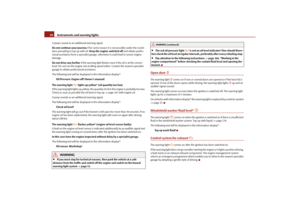 31
31 32
32 33
33 34
34 35
35 36
36 37
37 38
38 39
39 40
40 41
41 42
42 43
43 44
44 45
45 46
46 47
47 48
48 49
49 50
50 51
51 52
52 53
53 54
54 55
55 56
56 57
57 58
58 59
59 60
60 61
61 62
62 63
63 64
64 65
65 66
66 67
67 68
68 69
69 70
70 71
71 72
72 73
73 74
74 75
75 76
76 77
77 78
78 79
79 80
80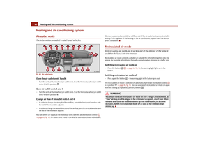 81
81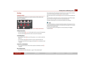 82
82 83
83 84
84 85
85 86
86 87
87 88
88 89
89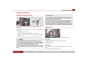 90
90 91
91 92
92 93
93 94
94 95
95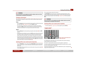 96
96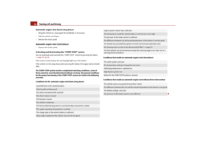 97
97 98
98 99
99 100
100 101
101 102
102 103
103 104
104 105
105 106
106 107
107 108
108 109
109 110
110 111
111 112
112 113
113 114
114 115
115 116
116 117
117 118
118 119
119 120
120 121
121 122
122 123
123 124
124 125
125 126
126 127
127 128
128 129
129 130
130 131
131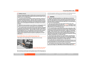 132
132 133
133 134
134 135
135 136
136 137
137 138
138 139
139 140
140 141
141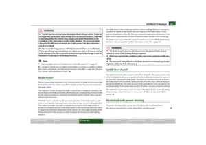 142
142 143
143 144
144 145
145 146
146 147
147 148
148 149
149 150
150 151
151 152
152 153
153 154
154 155
155 156
156 157
157 158
158 159
159 160
160 161
161 162
162 163
163 164
164 165
165 166
166 167
167 168
168 169
169 170
170 171
171 172
172 173
173 174
174 175
175 176
176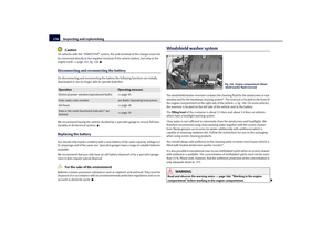 177
177 178
178 179
179 180
180 181
181 182
182 183
183 184
184 185
185 186
186 187
187 188
188 189
189 190
190 191
191 192
192 193
193 194
194 195
195 196
196 197
197 198
198 199
199 200
200 201
201 202
202 203
203 204
204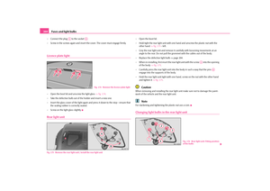 205
205 206
206 207
207 208
208 209
209 210
210 211
211 212
212 213
213 214
214 215
215 216
216 217
217 218
218 219
219 220
220 221
221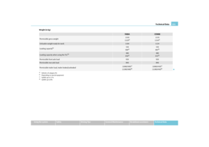 222
222 223
223 224
224 225
225 226
226 227
227 228
228 229
229 230
230 231
231 232
232 233
233 234
234 235
235 236
236 237
237 238
238 239
239 240
240 241
241 242
242 243
243