Page 65 of 244

Seats and Storage
64
Never transport occupants in the luggage compartment.Caution
Please ensure that the heating elements of the rear window heater are not damaged as a result of objects sliding in this area.
Note
Tyre pressure must be adjusted to the load
page 178, fig. 147
.
Vehicles of category N1On vehicles of the category
N1, which are not fitted with a protective grille, a lashing
set which complies with the standard EN 12195
(1 - 4) must be used for fastening the
load.Fastening elementsFig. 56 Luggage compartment: Lashing eyes and fastening elements (Fabia) / (Combi)Eyes and fastening elements are located on
the sides of the luggage compartment for
securing the items of luggage
fig. 56
.
You can also attach fixing ne
ts* to these eyes and fastening elements for holding small
objects.
WARNING
The load to be transported must be fixed in place in such a way that it cannot
move during the journey and when braking.
If the items of luggage or objects are
attached to the lashing eyes with
unsuitable or damaged lashing straps, inju
ries can occur in the event of braking
manoeuvres or accidents. In order to prevent the items of luggage being thrown forward, always use suitable lashing st
raps which are firmly attached to the
lashing eyes.Fixing nets - Net programme* (Combi)Fig. 57 Fixing net: double horizontal pocket
, floor fixing net / double vertical pockets
Fixing examples of the fixing net as do
uble horizontal pocket, floor fixing net
fig. 57
- left, and double vertical pockets
fig. 57
- right.
The fixing nets* for small items of luggage
and the installation instruction are located
in the luggage compartment.
WARNING
The whole strength of the net makes it possible to load the pocket with
objects of up to 5 kg in weight. Heavy objects are not secured sufficiently - risk of injury and net damage!
The load to be transported must be fixed in place in such a way that it cannot
move during the journey and when braking.
WARNING (continued)
s3j8.a.book Page 64 Tuesday, April 20, 2010 1:10 PM
Page 66 of 244

Seats and Storage
65
Using the system
Safety
Driving Tips
General Maintenance
Breakdown assistance
Technical Data
Caution
Do not place any objects with sharp edges in the nets - risk of net damage.Folding hooks*Folding hooks for attaching small items of lu
ggage, such as bags etc., are provided on
both sides of the luggage compartment
fig. 58
.
An item of luggage weighing up to
10 kg can be attached to the hook.
WARNING
Please refer to the following guidelines
page 63.
Luggage compartment cover You can use the luggage compartment cover behind the head restraints for storing
light and soft items.
Fig. 59 Remove / install the luggage compartment coverThe luggage compartment cover can be remo
ved as required if one must transport
bulky goods. – Unhook the support straps
fig. 59
.
– Remove the luggage compartment cover from the holders with adequate
blows to the bottom side of the cove
r in the area between the holders.
– To re-install, place the cover on the cont
act surfaces of the side trim panel and
position the mounts on the cover above
the holders at the side trim panel.
– Interlock the cover with adequate blows to
the top side of the cover in the area
between the holders.
– Attach the support straps on the boot lid. The luggage compartment cover is foreseen for
storage of small objects of up to 2.5 kg.
in weight.
WARNING
No objects should be placed on the
luggage compartment cover, the vehicle
occupants could be endangered if th
ere is sudden braking or the vehicle
collides with something.
Fig. 58 Luggage compartment: folding hook (Fabia)
A1
A2
A3
A2
A1
s3j8.a.book Page 65 Tuesday, April 20, 2010 1:10 PM
Page 67 of 244

Seats and Storage
66
Caution
When closing the boot lid, jamming and da
mage to the luggage compartment cover or
the side trim panel can occur
if handled in an unprofessional way. Therefore, check the
following before closing:
The mounts of the cover must be interlocked on the holders of the side trim
panel .
The items which are transported must not exceed the level of the luggage compart-
ment cover.
The cover must not be jammed in the seal of
the boot lid when it is in the opened
position.
There must be no object in the gap between the opened cover and the rear seat
backrest.
Please ensure that the heating elements
of the rear window heater are not
damaged as a result of objects placed in this area.
Note
When opening the boot lid, lift the luggage compartment cover - risk that objects placed in this area can slip forward!Further positions of the luggage compartment cover You can use the luggage compartment cover behind the head restraints for storing light and soft items.Fig. 60 Luggage compartment cover in the lowe
r position / stowed behind the rear seats
The luggage compartment cover can also be
put into the lower position on the
supporting elements
fig. 60
- left.
The luggage compartment cover can also
be stowed behind the rear seats
fig. 60
-
right.Foldable luggage compartment cover (Combi)Fig. 61 Luggage compartment: Foldable luggage
compartment cover / removing the foldable
luggage compartment coverPulling out– Pull the foldable luggage compartment cover in direction of arrow as far as the
stop into the secured position
fig. 61
.
Folding– Press the cover in the handle area in di
rection of arrow , the cover rolls up auto-
matically.
Removing– Have the foldable luggage compartment cover removed to transport bulky goods
by pressing on the side of
the cross rod in direction of arrow and taking it out
by moving it in direction of arrow
fig. 61
.
A3
A2
A1
A2
A3
A4
s3j8.a.book Page 66 Tuesday, April 20, 2010 1:10 PM
Page 68 of 244

Seats and Storage
67
Using the system
Safety
Driving Tips
General Maintenance
Breakdown assistance
Technical Data
WARNING
No objects should be placed on the luggage compartment cover, the vehicle occupants could be endangered if th
ere is sudden braking or the vehicle
collides with something.
Caution
Please ensure that the heating elements of the rear window heater and the foldable luggage compartment cover are not damaged as
a result of objects transported in this
area.Variable loading floor in the luggage compartment* (Combi)Remove variable loading floorFig. 62 Luggage compartment: Fold up variable loading floor / removeThe variable loading floor makes it easier to handle bulky goods and creates an even luggage compartment floor when the rear seats are folded forward. The maximum permissable surface load of the variable loading floor is 75 kg.Removing the variable loading floor– Unlock the variable loading floor by turning the locking bolts by approx. 180° to
the left
fig. 62
.
– You can fold together the variable loading
floor by moving it in the direction of the
arrow.
– Lift up the variable loading floor in direction of arrow
fig. 62
and take out the
loading floor by pulling in direction of arrow
fig. 62
.
Installing the variable loading floor– Place the variable loading floor once
folded together onto the carrier rails.
– Fold open the variable loading floor.– Lock the variabble loading floor by turning the locking bolts by approx. 180° to
the right.
WARNING
Pay attention when installing that the ca
rrier rails and the va
riable loading floor
are correctly fixed, otherwis
e the occupants are at risk.
Note
If the variable loading floor* is installed
page 67 in the luggage compartment, no
flexible storage compartment or fixing net*
page 64 can be installed.
Remove carrier railsFig. 63 Luggage compartment: Slacken
check points / remove carrier rails
AA
A1
A2
AA
s3j8.a.book Page 67 Tuesday, April 20, 2010 1:10 PM
Page 69 of 244

Seats and Storage
68 Remove carrier rails– Slacken the check points on the carrier rails using the vehicle key or a flat screw-
driver
page 67, fig. 63
.
– Grasp the carrier rail
at the position
page 67, fig. 63
and slacken it by
pulling in the direction of the arrow.
You can take out the removable storage
compartments* in order to facilitate the removal
page 78, “Removeable storage
compartments* in the luggage compartment”.
– Grasp the carrier rail at the position ,
slacken it by pulling in the direction of
the arrow and take it out.
– The carrier rail on the other side of
the luggage compartment can be removed in
the same way.
Install carrier rails– Position the carrier rails on the
sides of the luggage compartment.
– Press both check points on each carrier rail up to the stop.– Check the attachment of the
carrier rails by pulling it.
WARNING
Pay attention when installing that the ca
rrier rails and the variable loading floor
are correctly fixed, otherwise
the occupants are at risk.
Divide the luggage compartment with variable loading floor*
The luggage compartment can be divided with the variable loading floor. – Lift up the part with the holder and se
cure it by sliding it into the grooves
fig. 64
.
Net partition* (Combi)Use the net partition behind the rear seatsFig. 65 Pull out the net partition / roll upPulling out– Open the right rear door. – Fold down the rear seat backrests slightly forwards, which makes it possible to clear
the access for unrolling the net partition.
– Pull the net partition at the bracket out of the housing in direction of the
holders
fig. 65
.
– Insert the cross rod into one of the mounts .– Insert the other end of the cross rod by pressing into the second mount.– Press both ends of the cross rod
forward into the function position.
– Then push the seat backrest back into th
e upright position until the locking button
clicks into place - check by pulling on the seat backrest
.
AB
AA
A1
AA
A2
Fig. 64 Divide the luggage compart- ment
AA
AB
AC
AC
s3j8.a.book Page 68 Tuesday, April 20, 2010 1:10 PM
Page 70 of 244

Seats and Storage
69
Using the system
Safety
Driving Tips
General Maintenance
Breakdown assistance
Technical Data
Folding– Pull the cross rod back slightly, first on the one side then on the other side and take
the cross rod out of the mounts
page 68, fig. 65
.
–
Hold
the cross rod in such a way that the net partition can roll up slowly and
without damage into housing .
If you wish to use the entire luggage
compartment, you can remove the luggage
compartment cover
page 66.
WARNING
Ensure that the seat backrest on the rear seats is securely interlocked in
position when the vehicle is fitted with three-point safety belts for the middle rear seat. It is only then that the three-point seat belt can reliably fulfil its func-tion.
First check for yourself that the cross road is inserted into the mounts in
the front position!
If the net partition is located behind th
e rear seats, then always make sure
that the rear seat backrest is correctly interlocked.Using the net partition behind the front seatsFig. 66 Pull out the net partition / roll upPulling out– Open the right rear door.
– Fold the surfaces of the seats and seat backrests of the rear seats forward. – Pull the net partiton net at the plate out of the housing
fig. 66
.
– First of all insert the cross rod into the mount on one side.– Insert into the mount on the other side the second end of the cross rod.– Press both ends of the cross rod
forward into the function position.
Folding– Pull the cross rod back slightly, first on the one side then on the other side and take
the cross rod out of the mounts
fig. 66
.
–
Hold
the cross rod in such a way that the net partition can roll up slowly and
without damage into housing .
– Fold the rear seats back into their original position.
WARNING
First check for yourself that the cross road is inserted into the mounts in the front position!Removing and installing net partition housingRemoving– Open the right rear door.
ACAB
AC
AA
AB
AC
ACAB
AC
Fig. 67 Rear seats: Net partition housing
s3j8.a.book Page 69 Tuesday, April 20, 2010 1:10 PM
Page 71 of 244

Seats and Storage
70– Fold the surfaces of the seats and seat backrests of the rear seats forward. First the
right then the left backrest.
– Push the net partition housing
page 69, fig. 67
in the direction of arrow
and take it out of the mounts of the rear se
at backrests on the right in the direction
of the arrow .
Installing– Position the net partition housing into the mounts of the rear seat backrests. – Push the luggage net partition housing in
the opposite direction of arrow as far
as the stop.
– Fold the rear seats back into their original position.Bicycle holder in the luggage compartment*Install cross member– Remove the luggage compartment cover
page 66; if necessary we recommend
to remove, the net partition*
page 69.
– Take the head restraints out of the rear
seat backrests and fold the rear seats in
order to extend the luggage compartment as desired.
– Release the fixtures at the ends of
the cross member by fully loosening and
slightly pulling up
the securing screws . The fixtures open when they are not
already opened.
– Position the cross member with the fixed
(not pulled out) part onto the right (in
direction of travel) lashing eye and then the pull out part onto the left lashing eye.
– Press the fixtures on both sides of the cross member until they lock in place and
tighten the securing screws .
– Check the attachment of the cross member by pulling it.
WARNING
When transporting the bicycles in the
luggage compartment, ensure the safety
of the passengers transported.Install bicycle carrier– Position the approved bicycle carrier on
the middle of the cross member, after
pulling up the screw push the frame side rail (alu-part) towards the cross member and screw the screw into the nut
fig. 69
.
– Slacken the screw and take it out of the moveable part of the fixture; position
the moveable part of the carr
ier, depending on bicycle size
, into one of the possible
positions, so that it does not come in contact with the boot lid. We recommend to place the moveable part of the fixture in such a position that the holes are visible between the screw and the moveable part.
– Insert the screw into the desired position and tighten.
AA
A1
A2
A1
Fig. 68 Install cross member
AB
AC
AA
AB
AC
Fig. 69 Install bicycle carrier
AA
AA
ABAA
AB
s3j8.a.book Page 70 Tuesday, April 20, 2010 1:10 PM
Page 72 of 244

Seats and Storage
71
Using the system
Safety
Driving Tips
General Maintenance
Breakdown assistance
Technical Data
Put bicycle into the bicycle carrierFig. 70 Put in the bicycle / fastening the front wheel– Remove the front wheel before putti
ng the bicycle into the vehicle.
– Slacken the quick tension jack on the fixi
ng axle of the bicycl
e carrier and adjust
according to the width
of the bicycle fork.
– Fit the bicycle fork onto
the fixing axle and tighten with the quick tension jack
fig. 70
.
– Position the left pedal of the bicycle forward, in order to attach the front wheel
more easily.
– Slacken the screw
page 70, fig. 69
and push the bicycle
holder together with
the attached bicycle to the le
ft (in the direction of the arrow), so that no collision
between the steering arm and the side wi
ndow of the luggage compartment can
occur.
– Carefully guide the boot lid to the bottom
without letting it go and at the same time
check if there is adequate room between
the steering arm of the bicycle and the
window of the boot lid. If necessary adapt
the position of the moveable part of the
bicycle carrier in such a way that no collision can occur
page 70.
– It is best to push the removed front wheel between the crank of the left pedal and
the bicycle frame, attach it wi
th a strap to the front fork
fig. 70
, and/or to a fixing
point.
– Make sure that it does not lead to da
mage of the trim panel of the luggage
compartment, the bicycle and the placed objects.
– Perform the installation of the second
fixture and the attachment of the bicycle
analogously.
WARNING
Place the bicycles in the bicycle carrier in such a position that no collision between the steering arm and the side
and/or rear window can occur.
Note
If the front wheel is equipped with disc brake, attach the wheel in such a way that the brake disc is opposite the frame.Secure the stability of the bicycles with a strapFig. 71 Securing the bicycles with clamps / securing the bicycles with a strap– To slacken the rubber part of the clamp,
push both parts against each other and
open the clamp.
– Position the clamp with the rubber part to the front (in direction of travel) as far as
possible below the saddle
rod and close the clamp
fig. 71
.
– When transporting two bi
cycles tension the strap
fig. 71
between the saddle
rods, by pushing the bicycles apart.
– Hang the carabines at the ends of the strap into the lashing eyes behind the rear
seats.
– Pull the strap through the tensioning clasp,
first of all on the one side and then on
the other side.
AA
s3j8.a.book Page 71 Tuesday, April 20, 2010 1:10 PM
 1
1 2
2 3
3 4
4 5
5 6
6 7
7 8
8 9
9 10
10 11
11 12
12 13
13 14
14 15
15 16
16 17
17 18
18 19
19 20
20 21
21 22
22 23
23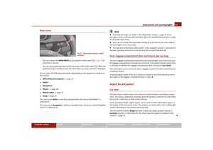 24
24 25
25 26
26 27
27 28
28 29
29 30
30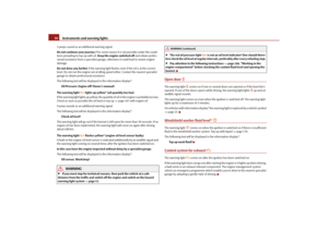 31
31 32
32 33
33 34
34 35
35 36
36 37
37 38
38 39
39 40
40 41
41 42
42 43
43 44
44 45
45 46
46 47
47 48
48 49
49 50
50 51
51 52
52 53
53 54
54 55
55 56
56 57
57 58
58 59
59 60
60 61
61 62
62 63
63 64
64 65
65 66
66 67
67 68
68 69
69 70
70 71
71 72
72 73
73 74
74 75
75 76
76 77
77 78
78 79
79 80
80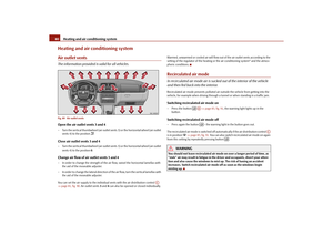 81
81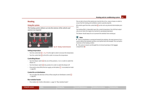 82
82 83
83 84
84 85
85 86
86 87
87 88
88 89
89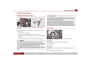 90
90 91
91 92
92 93
93 94
94 95
95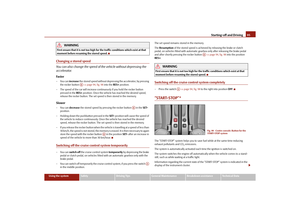 96
96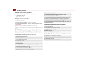 97
97 98
98 99
99 100
100 101
101 102
102 103
103 104
104 105
105 106
106 107
107 108
108 109
109 110
110 111
111 112
112 113
113 114
114 115
115 116
116 117
117 118
118 119
119 120
120 121
121 122
122 123
123 124
124 125
125 126
126 127
127 128
128 129
129 130
130 131
131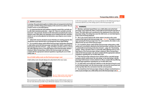 132
132 133
133 134
134 135
135 136
136 137
137 138
138 139
139 140
140 141
141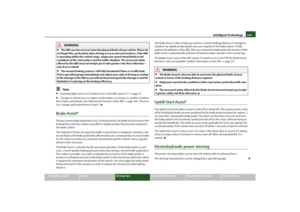 142
142 143
143 144
144 145
145 146
146 147
147 148
148 149
149 150
150 151
151 152
152 153
153 154
154 155
155 156
156 157
157 158
158 159
159 160
160 161
161 162
162 163
163 164
164 165
165 166
166 167
167 168
168 169
169 170
170 171
171 172
172 173
173 174
174 175
175 176
176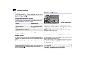 177
177 178
178 179
179 180
180 181
181 182
182 183
183 184
184 185
185 186
186 187
187 188
188 189
189 190
190 191
191 192
192 193
193 194
194 195
195 196
196 197
197 198
198 199
199 200
200 201
201 202
202 203
203 204
204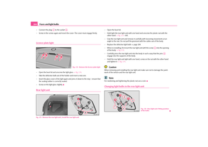 205
205 206
206 207
207 208
208 209
209 210
210 211
211 212
212 213
213 214
214 215
215 216
216 217
217 218
218 219
219 220
220 221
221 222
222 223
223 224
224 225
225 226
226 227
227 228
228 229
229 230
230 231
231 232
232 233
233 234
234 235
235 236
236 237
237 238
238 239
239 240
240 241
241 242
242 243
243