2010 JAGUAR XFR bearing
[x] Cancel search: bearingPage 747 of 3039

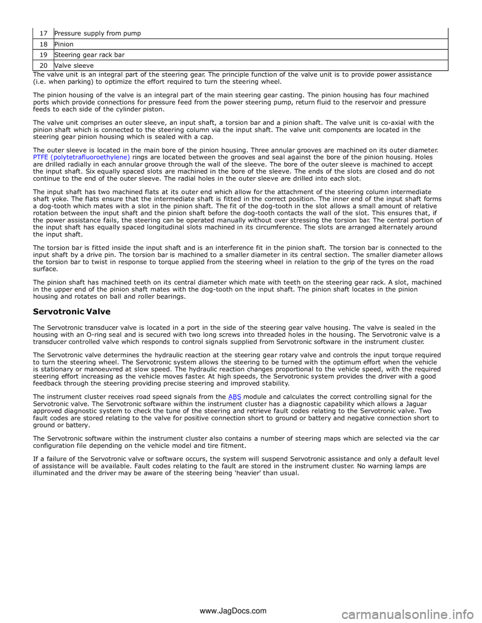
18 Pinion 19 Steering gear rack bar 20 Valve sleeve The valve unit is an integral part of the steering gear. The principle function of the valve unit is to provide power assistance
(i.e. when parking) to optimize the effort required to turn the steering wheel.
The pinion housing of the valve is an integral part of the main steering gear casting. The pinion housing has four machined
ports which provide connections for pressure feed from the power steering pump, return fluid to the reservoir and pressure
feeds to each side of the cylinder piston.
The valve unit comprises an outer sleeve, an input shaft, a torsion bar and a pinion shaft. The valve unit is co-axial with the
pinion shaft which is connected to the steering column via the input shaft. The valve unit components are located in the
steering gear pinion housing which is sealed with a cap.
The outer sleeve is located in the main bore of the pinion housing. Three annular grooves are machined on its outer diameter.
PTFE (polytetrafluoroethylene) rings are located between the grooves and seal against the bore of the pinion housing. Holes
are drilled radially in each annular groove through the wall of the sleeve. The bore of the outer sleeve is machined to accept
the input shaft. Six equally spaced slots are machined in the bore of the sleeve. The ends of the slots are closed and do not
continue to the end of the outer sleeve. The radial holes in the outer sleeve are drilled into each slot.
The input shaft has two machined flats at its outer end which allow for the attachment of the steering column intermediate
shaft yoke. The flats ensure that the intermediate shaft is fitted in the correct position. The inner end of the input shaft forms
a dog-tooth which mates with a slot in the pinion shaft. The fit of the dog-tooth in the slot allows a small amount of relative
rotation between the input shaft and the pinion shaft before the dog-tooth contacts the wall of the slot. This ensures that, if
the power assistance fails, the steering can be operated manually without over stressing the torsion bar. The central portion of
the input shaft has equally spaced longitudinal slots machined in its circumference. The slots are arranged alternately around
the input shaft.
The torsion bar is fitted inside the input shaft and is an interference fit in the pinion shaft. The torsion bar is connected to the
input shaft by a drive pin. The torsion bar is machined to a smaller diameter in its central section. The smaller diameter allows
the torsion bar to twist in response to torque applied from the steering wheel in relation to the grip of the tyres on the road
surface.
The pinion shaft has machined teeth on its central diameter which mate with teeth on the steering gear rack. A slot, machined
in the upper end of the pinion shaft mates with the dog-tooth on the input shaft. The pinion shaft locates in the pinion
housing and rotates on ball and roller bearings.
Servotronic Valve
The Servotronic transducer valve is located in a port in the side of the steering gear valve housing. The valve is sealed in the
housing with an O-ring seal and is secured with two long screws into threaded holes in the housing. The Servotronic valve is a
transducer controlled valve which responds to control signals supplied from Servotronic software in the instrument cluster.
The Servotronic valve determines the hydraulic reaction at the steering gear rotary valve and controls the input torque required
to turn the steering wheel. The Servotronic system allows the steering to be turned with the optimum effort when the vehicle
is stationary or manoeuvred at slow speed. The hydraulic reaction changes proportional to the vehicle speed, with the required
steering effort increasing as the vehicle moves faster. At high speeds, the Servotronic system provides the driver with a good
feedback through the steering providing precise steering and improved stability.
The instrument cluster receives road speed signals from the ABS module and calculates the correct controlling signal for the Servotronic valve. The Servotronic software within the instrument cluster has a diagnostic capability which allows a Jaguar
approved diagnostic system to check the tune of the steering and retrieve fault codes relating to the Servotronic valve. Two
fault codes are stored relating to the valve for positive connection short to ground or battery and negative connection short to
ground or battery.
The Servotronic software within the instrument cluster also contains a number of steering maps which are selected via the car
configuration file depending on the vehicle model and tire fitment.
If a failure of the Servotronic valve or software occurs, the system will suspend Servotronic assistance and only a default level
of assistance will be available. Fault codes relating to the fault are stored in the instrument cluster. No warning lamps are
illuminated and the driver may be aware of the steering being 'heavier' than usual.
www.JagDocs.com
Page 776 of 3039

1 Steering wheel 2 Gear change paddle switch 3 Column adjust switch 4 Lower shroud 5 Rake adjustment housing 6 Reach adjustment housing 7 Column adjustment motor 8 Lower column - Upper collapse shaft 9 Bulkhead bearing and seal assembly 10 Lower column - Lower collapse shaft 11 Electric steering lock mechanism 12 Column mounting plate 13 Upper shroud
Page 780 of 3039

STEERING COLUMN Component Description
Item Description 1 Rake housing 2 Electric steering column lock 3 Mounting plate 4 Rake lever 5 Crash tube 6 Distance keeper 7 Steering wheel mounting splines 8 Steering angle sensor ring 9 Crash adaptor 10 Rake lever pivot bearing (2 off) 11 Flanged locknut (4 off) - mounting to cross-beam 12 Rake solenoid 13 Rake clutch 14 Spindle 15 Reach solenoid 16 Reach clutch 17 Column adjustment motor 18 Outer clamping yoke 19 Clamp bolt 20 Inner tube yoke
WARNING: Do not attempt to dismantle the steering column. The crash safety of the unit will be compromised.
The steering column is attached to the in-vehicle cross-beam and secured with 4 flanged lock nuts onto 4 studs integral with
the cross-beam.
Page 781 of 3039

1 Tube and clamping yoke pivot bearing 2 Tube yoke 3 Tolerance ring 4 Locking ring 5 Axial housing 6 Rake housing 7 Tube 8 Splined shaft 9 Crash adaptor 10 Steering angle sensor ring 11 Steering wheel mounting splines 12 Upper bearing 13 Column adjustment motor 14 Lower bearing
Page 782 of 3039

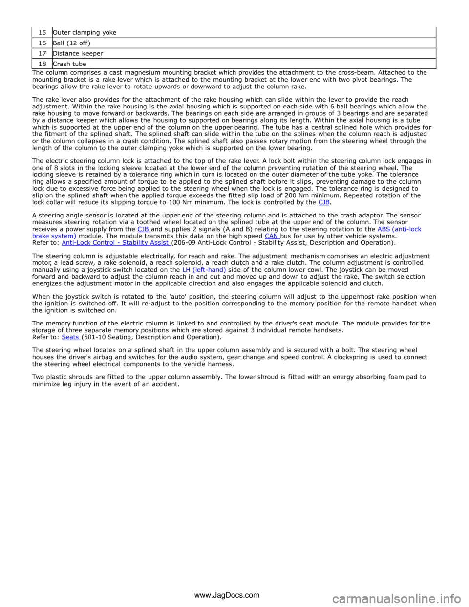
16 Ball (12 off) 17 Distance keeper 18 Crash tube The column comprises a cast magnesium mounting bracket which provides the attachment to the cross-beam. Attached to the
mounting bracket is a rake lever which is attached to the mounting bracket at the lower end with two pivot bearings. The
bearings allow the rake lever to rotate upwards or downward to adjust the column rake.
The rake lever also provides for the attachment of the rake housing which can slide within the lever to provide the reach
adjustment. Within the rake housing is the axial housing which is supported on each side with 6 ball bearings which allow the
rake housing to move forward or backwards. The bearings on each side are arranged in groups of 3 bearings and are separated
by a distance keeper which allows the housing to supported on bearings along its length. Within the axial housing is a tube
which is supported at the upper end of the column on the upper bearing. The tube has a central splined hole which provides for
the fitment of the splined shaft. The splined shaft can slide within the tube on the splines when the column reach is adjusted
or the column collapses in a crash condition. The splined shaft also passes rotary motion from the steering wheel through the
length of the column to the outer clamping yoke which is supported on the lower bearing.
The electric steering column lock is attached to the top of the rake lever. A lock bolt within the steering column lock engages in
one of 8 slots in the locking sleeve located at the lower end of the column preventing rotation of the steering wheel. The
locking sleeve is retained by a tolerance ring which in turn is located on the outer diameter of the tube yoke. The tolerance
ring allows a specified amount of torque to be applied to the splined shaft before it slips, preventing damage to the column
lock due to excessive force being applied to the steering wheel when the lock is engaged. The tolerance ring is designed to
slip on the splined shaft when the applied torque exceeds the fitted slip load of 200 Nm minimum. Repeated rotation of the
lock collar will reduce its slipping torque to 100 Nm minimum. The lock is controlled by the CJB.
A steering angle sensor is located at the upper end of the steering column and is attached to the crash adaptor. The sensor
measures steering rotation via a toothed wheel located on the splined tube at the upper end of the column. The sensor
receives a power supply from the CJB and supplies 2 signals (A and B) relating to the steering rotation to the ABS (anti-lock brake system) module. The module transmits this data on the high speed CAN bus for use by other vehicle systems. Refer to: Anti-Lock Control - Stability Assist (206-09 Anti-Lock Control - Stability Assist, Description and Operation).
The steering column is adjustable electrically, for reach and rake. The adjustment mechanism comprises an electric adjustment
motor, a lead screw, a rake solenoid, a reach solenoid, a reach clutch and a rake clutch. The column adjustment is controlled
manually using a joystick switch located on the LH (left-hand) side of the column lower cowl. The joystick can be moved
forward and backward to adjust the column reach in and out and moved up and down to adjust the rake. The switch selection
energizes the adjustment motor in the applicable direction and also engages the applicable solenoid and clutch.
When the joystick switch is rotated to the 'auto' position, the steering column will adjust to the uppermost rake position when
the ignition is switched off. It will re-adjust to the position corresponding to the memory position for the remote handset when
the ignition is switched on.
The memory function of the electric column is linked to and controlled by the driver's seat module. The module provides for the
storage of three separate memory positions which are stored against 3 individual remote handsets.
Refer to: Seats (501-10 Seating, Description and Operation).
The steering wheel locates on a splined shaft in the upper column assembly and is secured with a bolt. The steering wheel
houses the driver's airbag and switches for the audio system, gear change and speed control. A clockspring is used to connect
the steering wheel electrical components to the vehicle harness.
Two plastic shrouds are fitted to the upper column assembly. The lower shroud is fitted with an energy absorbing foam pad to
minimize leg injury in the event of an accident.
www.JagDocs.com
Page 783 of 3039

1 Yoke 2 Upper collapse shaft 3 Flexible coupling 4 Shaft plate 5 Rivet (4 off) 6 Upper tube 7 Plastic sleeve 8 Boot 9 Bearing (4 off) 10 Teeth tube 11 Lower shaft 12 Yoke clamp bolt (2 off) 13 Bearing (4 off) 14 Lower yoke 15 Spider 16 Upper yoke The lower shaft assembly comprises 2 splined shafts connected by a universal joint in the center.
The upper collapse shaft has a flexible couple at its upper end. The flexible coupling controls axial and torsional movements
and also assists with noise and vibration damping. The flexible coupling is fitted with a shaft plate which has a boss with
machined flats on it. The flats provide positive location on the upper column outer clamping yoke. A cut-out in the boss allows
for the fitment of a clamping bolt to secure the upper column outer clamping yoke. The cut-out ensures that the lower shaft
assembly can only be fitted in one orientation.
The upper collapse shaft is connected to the stopper plate of the flexible coupling with splines. The stopper plate is connected
to the shaft plate via the flexible coupling and is secured with rivets. The upper collapse shaft has a series of splines which
engage with the upper tube. The splines allow the upper collapse shaft to slide into the upper tube in the event of an
accident.
The upper tube is positively connected to the upper half of the yoke of the universal joint. A plastic tube is located around the
upper tube and provides for the attachment of a boot which seals the lower shaft assembly where it passes through the
vehicle bulkhead. LOWER SHAFT ASSEMBLY
Page 825 of 3039

Published: 11-May-2011
Engine System - General Information - Cylinder Bore Out-of-Round
General Procedures
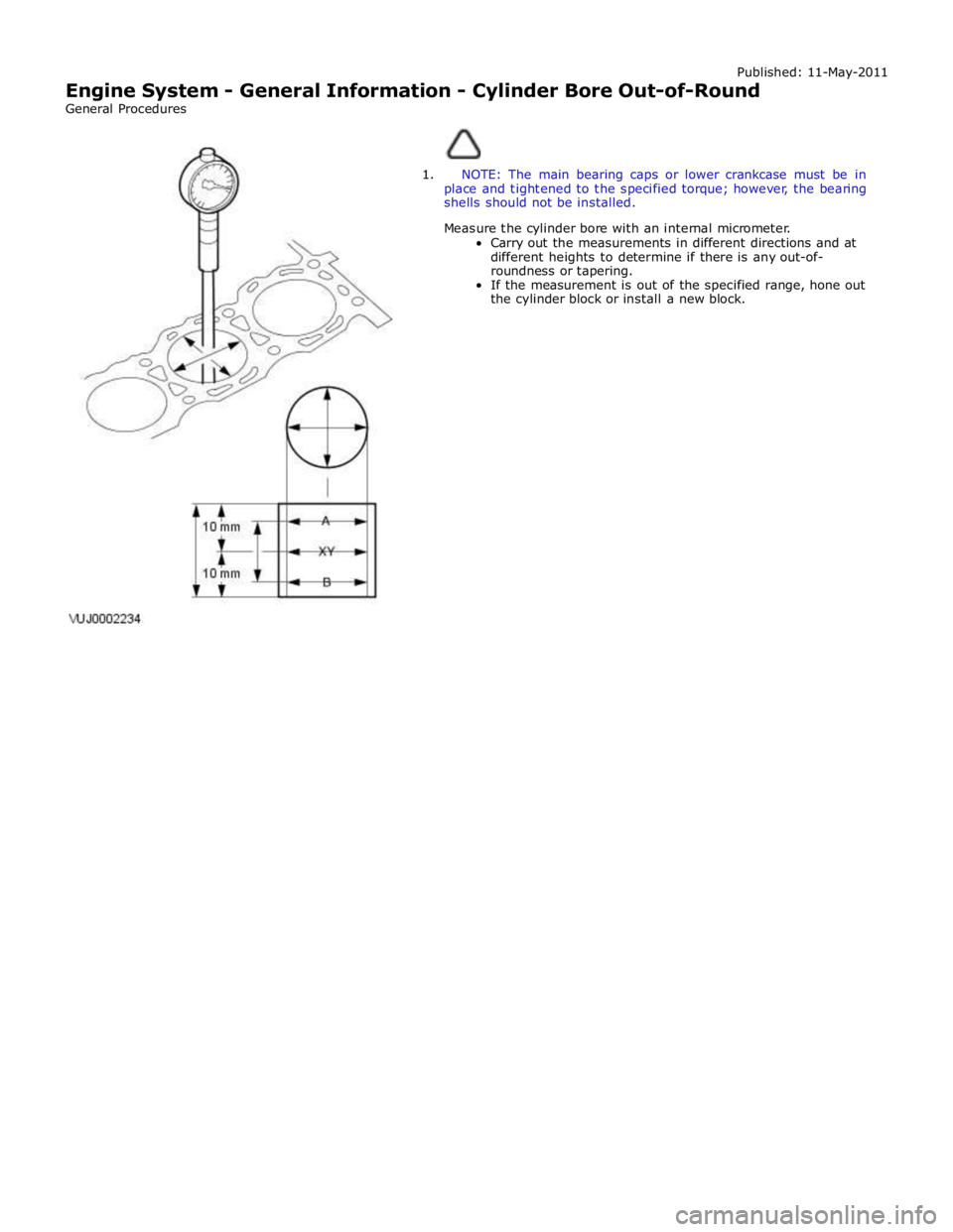
1. NOTE: The main bearing caps or lower crankcase must be in
place and tightened to the specified torque; however, the bearing
shells should not be installed.
Measure the cylinder bore with an internal micrometer.
Carry out the measurements in different directions and at
different heights to determine if there is any out-of-
roundness or tapering.
If the measurement is out of the specified range, hone out
the cylinder block or install a new block.
Page 844 of 3039

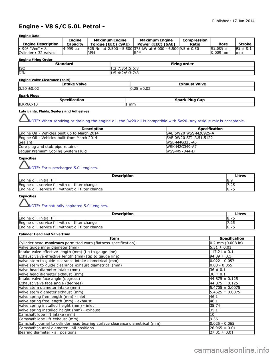
Engine - V8 S/C 5.0L Petrol -
Engine Data Published: 17-Jun-2014
Engine Description Engine Capacity Maximum Engine Torque (EEC) (SAE) Maximum Engine
Power (EEC) (SAE) Compression
Ratio
Bore
Stroke • 90° "Vee" • 8 Cylinder • 32 Valves 4.999 ccm
625 Nm at 2.500 - 5.500
RPM 375 kW at 6.000 - 6.500
RPM 9.5 ± 0.50 92.509 ±
0.009 mm 93 ± 0.1
mm Engine Firing Order
Standard Firing order ISO 1:2:7:3:4:5:6:8 DIN 1:5:4:2:6:3:7:8 Engine Valve Clearance (cold)
Intake Valve Exhaust Valve 0.20 ±0.02 0.25 ±0.02 Spark Plugs
Specification Spark Plug Gap ILKR6C-10 1 mm Lubricants, Fluids, Sealers and Adhesives
NOTE: When servicing or draining the engine oil, the 0w20 oil is compatible with 5w20. Any residue mix is acceptable.
Description Specification Engine Oil - Vehicles built up to March 2014 SAE 5W20 WSS-M2C925-A Engine Oil - Vehicles built from March 2014 SAE 0W20 STJLR.51.5122 Sealant WSE-M4G323-A6 Core plug and stub pipe retainer WSK-M2G349-A7 Jaguar Premium Cooling System Fluid WSS-M97B44-D Capacities
NOTE: For supercharged 5.0L engines.
Description Litres Engine oil, initial fill 8.9 Engine oil, service fill with oil filter change 7.25 Engine oil, service fill without oil filter change 6.75 Capacities
NOTE: For naturally aspirated 5.0L engines.
Description Litres Engine oil, initial fill 8.75 Engine oil, service fill with oil filter change 7.25 Engine oil, service fill without oil filter change 6.75 Cylinder Head and Valve Train
Item Specification Cylinder head maximum permitted warp (flatness specification) 0.2 mm (0.008 in) Valve guide inner diameter (mm) 5.51 ± 0.01 Intake valve effective length (mm) (tip to gauge line) 117.21 ± 0.1 Exhaust valve effective length (mm) (tip to gauge line) 94.39 ± 0.1 Valve stem to guide clearance intake diametrical (mm) 0.022 - 0.057 Valve stem to guide clearance exhaust diametrical (mm) 0.03 - 0.065 Valve head diameter intake (mm) 36 ± 0.1 Valve head diameter exhaust (mm) 30 ± 0.1 Intake valve face angle (degrees) 44.875 ± 0.125 Exhaust valve face angle (degrees) 44.875 ± 0.125 Valve stem diameter intake (mm) 5.4705 ± 0.0075 Valve stem diameter exhaust (mm) 5.4625 ± 0.0075 Valve spring free length (mm) - inlet 46.1 Valve spring free length (mm) - exhaust 46.1 Valve spring installed height (mm) - inlet 35.74 Valve spring installed height (mm) - exhaust 35.1 Camshaft lobe lift intake (mm) 10 Camshaft lobe lift exhaust (mm) 9.36 Camshaft journal to cylinder head bearing surface clearance diametrical (mm) 0.025 - 0.065 Camshaft journal diameter - all positions 26.965 ± 0.01 Bearing diameter - all positions 27.01 ± 0.01