2010 JAGUAR XFR bearing
[x] Cancel search: bearingPage 905 of 3039

Engine - V8 S/C 5.0L Petrol - Camshaft RH
Removal and Installation
Removal Published: 11-May-2011
CAUTION: Make sure that the orientation and code on the top of the camshaft bearing caps is noted (along with the bank
- A or B), so that on installation the components are installed to their original position. Failure to follow this instruction may
cause damage to the vehicle.
NOTE: Removal steps in this procedure may contain installation details.
1. Refer to: Battery Disconnect and Connect (414-01 Battery, Mounting and Cables, General Procedures).
2. WARNING: Make sure to support the vehicle with axle stands.
Raise and support the vehicle.
3.
4. CAUTIONS:
Rotate the camshafts until all the valves are at their
minimum open point.
Evenly and progressively, release the camshaft
bearing caps.
NOTE: Remove the camshaft bearing caps. Note: their
position, orientation and markings. Each is marked with its
position (number) and an orientation (arrow).
Page 906 of 3039

Installation
1. CAUTIONS:
Prior to installing the camshafts, position the
crankshaft 45 degrees ATDC cylinder 1A to prevent
valve/piston collision.
Evenly and progressively install and tighten the
camshaft bearing caps.
Make sure that the camshafts and camshaft bearing
caps are installed in their original locations.
NOTE: Lubricate the camshafts and the camshaft
bearing caps with EP90 oil (or 75/90 viscosity oil will
suffice) prior to installation.
Torque: 3 Nm
2. NOTE: Tighten the bolts in the indicated sequence.
Torque: 12 Nm
3. CAUTION: Only rotate the crankshaft clockwise.
Rotate the crankshaft untill the camshaft lobe on the valve being
checked is 180 degrees from the maximum opening position.
4. NOTE: If the valve clearance is incorrect, continue to the next step. If
the valve clearance is correct, continue to step 8.
Using feeler gauge check the gap between the tappet and the camshaft
lobe and check against specifications table.
5. CAUTIONS:
Use the following formula to calculate the required bucket
thickness. Original thickness + measured clearance - desired clearance =
required bucket thickness.
Do not use a magnet to remove the tappet.
Remove the tappet and measure the thickness. www.JagDocs.com
Page 1115 of 3039
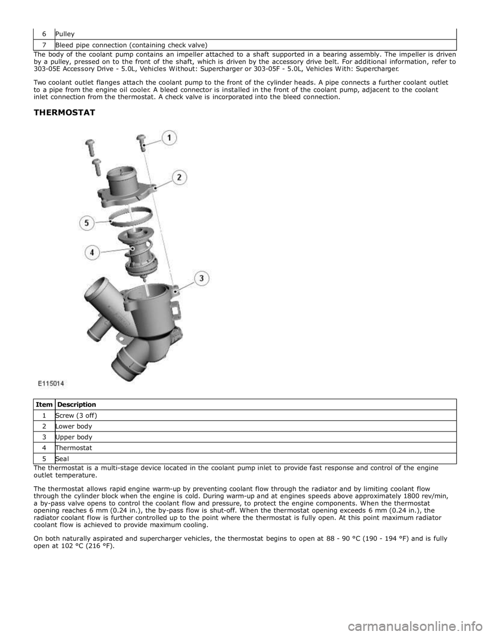
7 Bleed pipe connection (containing check valve) The body of the coolant pump contains an impeller attached to a shaft supported in a bearing assembly. The impeller is driven
by a pulley, pressed on to the front of the shaft, which is driven by the accessory drive belt. For additional information, refer to
303-05E Accessory Drive - 5.0L, Vehicles Without: Supercharger or 303-05F - 5.0L, Vehicles With: Supercharger.
Two coolant outlet flanges attach the coolant pump to the front of the cylinder heads. A pipe connects a further coolant outlet
to a pipe from the engine oil cooler. A bleed connector is installed in the front of the coolant pump, adjacent to the coolant
inlet connection from the thermostat. A check valve is incorporated into the bleed connection.
THERMOSTAT
Item Description 1 Screw (3 off) 2 Lower body 3 Upper body 4 Thermostat 5 Seal The thermostat is a multi-stage device located in the coolant pump inlet to provide fast response and control of the engine
outlet temperature.
The thermostat allows rapid engine warm-up by preventing coolant flow through the radiator and by limiting coolant flow
through the cylinder block when the engine is cold. During warm-up and at engines speeds above approximately 1800 rev/min,
a by-pass valve opens to control the coolant flow and pressure, to protect the engine components. When the thermostat
opening reaches 6 mm (0.24 in.), the by-pass flow is shut-off. When the thermostat opening exceeds 6 mm (0.24 in.), the
radiator coolant flow is further controlled up to the point where the thermostat is fully open. At this point maximum radiator
coolant flow is achieved to provide maximum cooling.
On both naturally aspirated and supercharger vehicles, the thermostat begins to open at 88 - 90 °C (190 - 194 °F) and is fully
open at 102 °C (216 °F).
Page 1295 of 3039
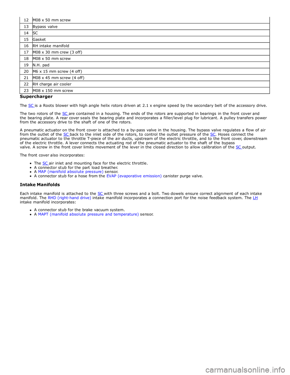
13 Bypass valve 14 SC 15 Gasket 16 RH intake manifold 17 M08 x 30 mm crew (3 off) 18 M08 x 50 mm screw 19 N.H. pad 20 M6 x 15 mm screw (4 off) 21 M08 x 45 mm screw (4 off) 22 RH charge air cooler 23 M08 x 150 mm screw Supercharger
The SC is a Roots blower with high angle helix rotors driven at 2.1 x engine speed by the secondary belt of the accessory drive.
The two rotors of the SC are contained in a housing. The ends of the rotors are supported in bearings in the front cover and the bearing plate. A rear cover seals the bearing plate and incorporates a filler/level plug for lubricant. A pulley transfers power
from the accessory drive to the shaft of one of the rotors.
A pneumatic actuator on the front cover is attached to a by-pass valve in the housing. The bypass valve regulates a flow of air
from the outlet of the SC back to the inlet side of the rotors, to control the outlet pressure of the SC. Hoses connect the pneumatic actuator to the throttle T-piece of the air ducts, upstream of the electric throttle, and to the front cover, downstream
of the electric throttle. A lever connects the actuating rod of the pneumatic actuator to the shaft of the bypass
valve. A screw in the front cover limits movement of the lever in the closed direction to allow calibration of the SC output. The front cover also incorporates:
The SC air inlet and mounting face for the electric throttle. A connector stub for the part load breather.
A MAP (manifold absolute pressure) sensor.
A connector stub for a hose from the EVAP (evaporative emission) canister purge valve.
Intake Manifolds
Each intake manifold is attached to the SC with three screws and a bolt. Two dowels ensure correct alignment of each intake manifold. The RHD (right-hand drive) intake manifold incorporates a connection port for the noise feedback system. The LH intake manifold incorporates:
A connector stub for the brake vacuum system.
A MAPT (manifold absolute pressure and temperature) sensor.
Page 1428 of 3039
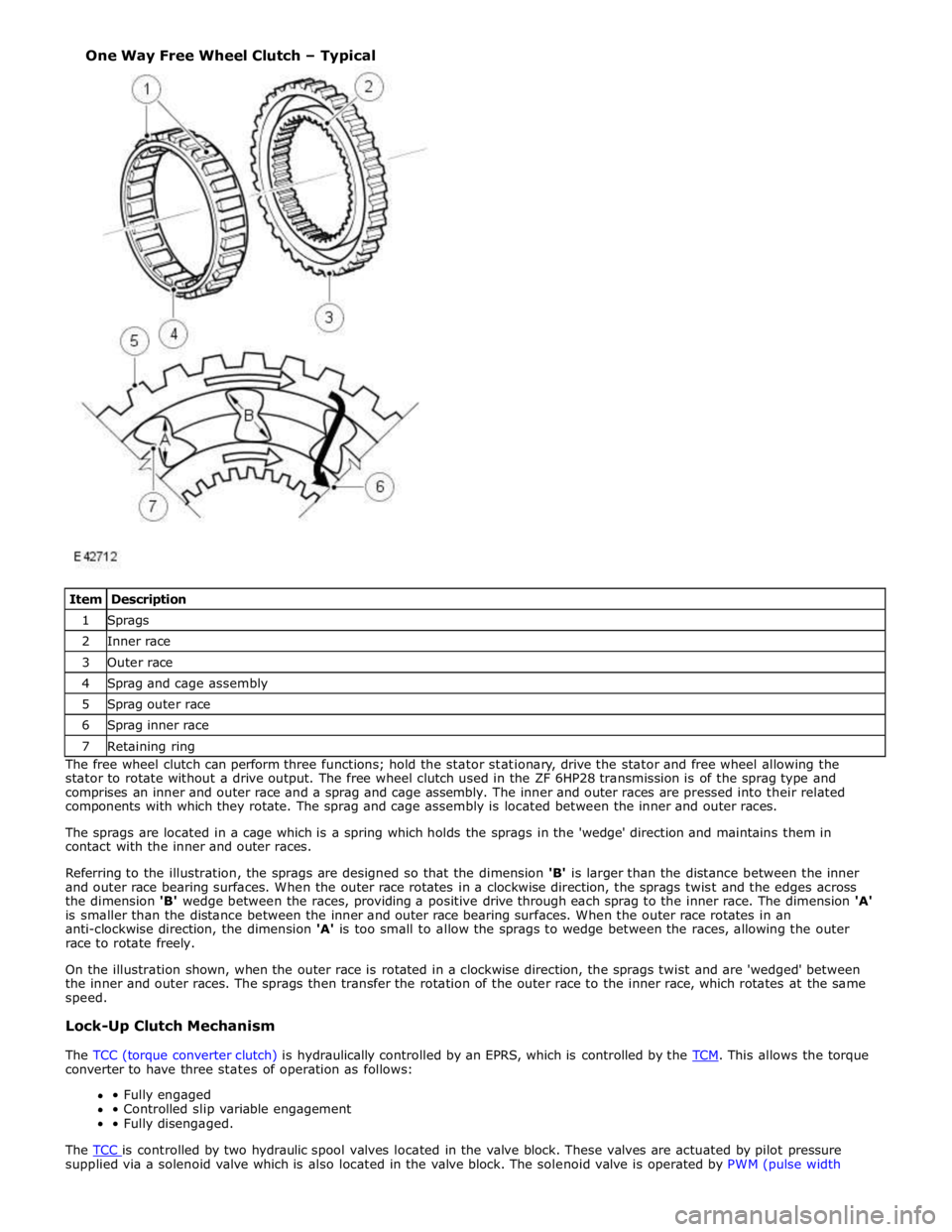
1 Sprags 2 Inner race 3 Outer race 4 Sprag and cage assembly 5 Sprag outer race 6 Sprag inner race 7 Retaining ring The free wheel clutch can perform three functions; hold the stator stationary, drive the stator and free wheel allowing the
stator to rotate without a drive output. The free wheel clutch used in the ZF 6HP28 transmission is of the sprag type and
comprises an inner and outer race and a sprag and cage assembly. The inner and outer races are pressed into their related
components with which they rotate. The sprag and cage assembly is located between the inner and outer races.
The sprags are located in a cage which is a spring which holds the sprags in the 'wedge' direction and maintains them in
contact with the inner and outer races.
Referring to the illustration, the sprags are designed so that the dimension 'B' is larger than the distance between the inner
and outer race bearing surfaces. When the outer race rotates in a clockwise direction, the sprags twist and the edges across
the dimension 'B' wedge between the races, providing a positive drive through each sprag to the inner race. The dimension 'A'
is smaller than the distance between the inner and outer race bearing surfaces. When the outer race rotates in an
anti-clockwise direction, the dimension 'A' is too small to allow the sprags to wedge between the races, allowing the outer
race to rotate freely.
On the illustration shown, when the outer race is rotated in a clockwise direction, the sprags twist and are 'wedged' between
the inner and outer races. The sprags then transfer the rotation of the outer race to the inner race, which rotates at the same
speed.
Lock-Up Clutch Mechanism
The TCC (torque converter clutch) is hydraulically controlled by an EPRS, which is controlled by the TCM. This allows the torque converter to have three states of operation as follows:
• Fully engaged
• Controlled slip variable engagement
• Fully disengaged.
The TCC is controlled by two hydraulic spool valves located in the valve block. These valves are actuated by pilot pressure supplied via a solenoid valve which is also located in the valve block. The solenoid valve is operated by PWM (pulse width One Way Free Wheel Clutch – Typical
Page 1430 of 3039
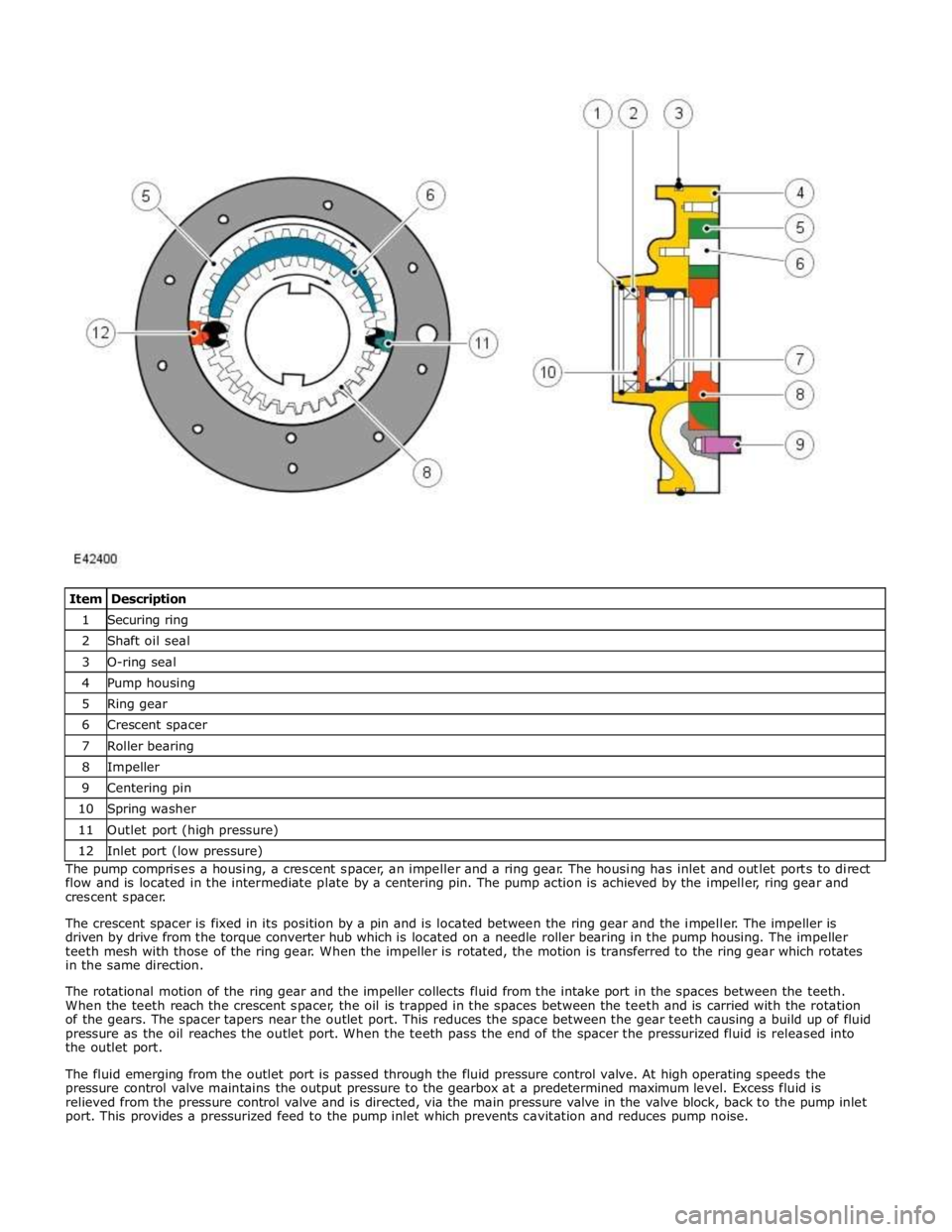
1 Securing ring 2 Shaft oil seal 3 O-ring seal 4 Pump housing 5 Ring gear 6 Crescent spacer 7 Roller bearing 8 Impeller 9 Centering pin 10 Spring washer 11 Outlet port (high pressure) 12 Inlet port (low pressure) The pump comprises a housing, a crescent spacer, an impeller and a ring gear. The housing has inlet and outlet ports to direct
flow and is located in the intermediate plate by a centering pin. The pump action is achieved by the impeller, ring gear and
crescent spacer.
The crescent spacer is fixed in its position by a pin and is located between the ring gear and the impeller. The impeller is
driven by drive from the torque converter hub which is located on a needle roller bearing in the pump housing. The impeller
teeth mesh with those of the ring gear. When the impeller is rotated, the motion is transferred to the ring gear which rotates
in the same direction.
The rotational motion of the ring gear and the impeller collects fluid from the intake port in the spaces between the teeth.
When the teeth reach the crescent spacer, the oil is trapped in the spaces between the teeth and is carried with the rotation
of the gears. The spacer tapers near the outlet port. This reduces the space between the gear teeth causing a build up of fluid
pressure as the oil reaches the outlet port. When the teeth pass the end of the spacer the pressurized fluid is released into
the outlet port.
The fluid emerging from the outlet port is passed through the fluid pressure control valve. At high operating speeds the
pressure control valve maintains the output pressure to the gearbox at a predetermined maximum level. Excess fluid is
relieved from the pressure control valve and is directed, via the main pressure valve in the valve block, back to the pump inlet
port. This provides a pressurized feed to the pump inlet which prevents cavitation and reduces pump noise.
Page 1432 of 3039
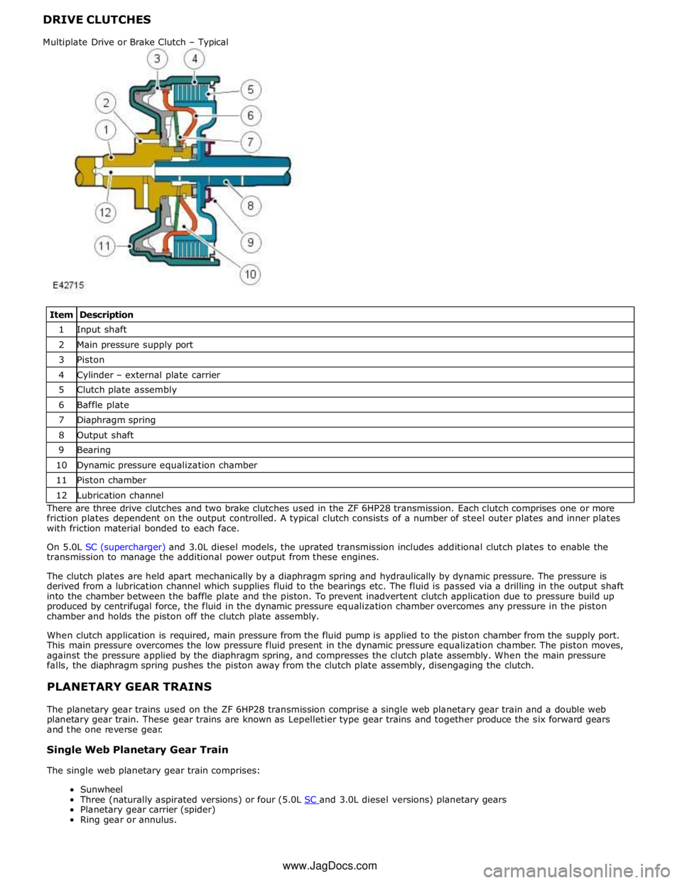
DRIVE CLUTCHES
Item Description 1 Input shaft 2 Main pressure supply port 3 Piston 4 Cylinder – external plate carrier 5 Clutch plate assembly 6 Baffle plate 7 Diaphragm spring 8 Output shaft 9 Bearing 10 Dynamic pressure equalization chamber 11 Piston chamber 12 Lubrication channel There are three drive clutches and two brake clutches used in the ZF 6HP28 transmission. Each clutch comprises one or more
friction plates dependent on the output controlled. A typical clutch consists of a number of steel outer plates and inner plates
with friction material bonded to each face.
On 5.0L SC (supercharger) and 3.0L diesel models, the uprated transmission includes additional clutch plates to enable the
transmission to manage the additional power output from these engines.
The clutch plates are held apart mechanically by a diaphragm spring and hydraulically by dynamic pressure. The pressure is
derived from a lubrication channel which supplies fluid to the bearings etc. The fluid is passed via a drilling in the output shaft
into the chamber between the baffle plate and the piston. To prevent inadvertent clutch application due to pressure build up
produced by centrifugal force, the fluid in the dynamic pressure equalization chamber overcomes any pressure in the piston
chamber and holds the piston off the clutch plate assembly.
When clutch application is required, main pressure from the fluid pump is applied to the piston chamber from the supply port.
This main pressure overcomes the low pressure fluid present in the dynamic pressure equalization chamber. The piston moves,
against the pressure applied by the diaphragm spring, and compresses the clutch plate assembly. When the main pressure
falls, the diaphragm spring pushes the piston away from the clutch plate assembly, disengaging the clutch.
PLANETARY GEAR TRAINS
The planetary gear trains used on the ZF 6HP28 transmission comprise a single web planetary gear train and a double web
planetary gear train. These gear trains are known as Lepelletier type gear trains and together produce the six forward gears
and the one reverse gear.
Single Web Planetary Gear Train
The single web planetary gear train comprises:
Sunwheel
Three (naturally aspirated versions) or four (5.0L SC and 3.0L diesel versions) planetary gears Planetary gear carrier (spider)
Ring gear or annulus. Multiplate Drive or Brake Clutch – Typical www.JagDocs.com
Page 2723 of 3039

Terotex HV 200 extra spray - 1L can Teroson 176.48 Terotex HV 200 extra spray - 10L tin Teroson 179.40A Terotex HV 200 extra spray - 60L barrel Teroson 170.96J Terotex HV 400 1L can Teroson 169.65Q Terotex HV 400 10L tin Teroson 169.76C Terotex HV 400 60L barrel Teroson 169.85M Teroson cavity spray 500ml aerosol Teroson 155.71A Underbody Wax - - Terotex wax black 1L can Teroson 114.59F Protective wax Teroson 122.73Q Underbody Coating - - Bodyguard stonechip coating (textured) can - black 3M 08868 Bodyguard stonechip coating (textured) can - white 3M 08878 Bodyguard stonechip coating (textured) can - grey 3M 08879 Bodyguard stonechip coating (flat) can - black 3M 08158 Bodyguard stonechip coating (flat) can - grey 3M 08159 Anti chip coating smooth - grey 3M 08886 Terotex record black 1L can Teroson 122.48N Terotex record light 1L can Teroson 165.53S Terotex anti chip compound light (UBC) 1L can Teroson 191.08V Terotex anti chip compound black (UBC) 1L can Teroson 191.32V Trim Adhesive - - Auto adhesive - aerosol - clear (trim) 3M 08080 Auto adhesive - brushable - clear (trim) 3M 08150 Contact adhesive - aerosol - amber 3M 08090 Corrosion Protection - - Zinc spray 3M 09113 Zinc spray Teroson 158.18T Anti Corrosive Agent - - Terotex HV 350 1L can Teroson 141.78L Terotex HV 350 10L can Teroson 160.02T Terotex HV 350 60L barrel Teroson 160.01S Sound Deadening - - Sound deadening sheets 3M 08840 Terodem SP 100 alu Teroson 190.33 Terodem SP 200 Teroson 190.55M Terodem SP 300 50 x 50 Teroson 145.28R Terodem SP 300 100 x 50 Teroson 134.29X Flexible Part Repair - - Flexible part repair material (FPRM) 3M 05900 Adhesives / Thread Locking - - Lock N Seal 243 thread locking Loctite 13701 Lock N Seal 243 thread locking Loctite 14131 Lock N Seal 243 thread locking Loctite 25684 Stud N Bearing fit 271 Loctite 13704 Stud N Bearing fit 271 Loctite 14130 Stud N Bearing fit 271 Loctite 25685 Pipe sealant 577 Loctite 16604 Pipe sealant 577 Loctite 25689 Pipe sealant 55 Loctite 31899 Gasket - - Multi gasket Loctite 25688 Silicone copper Loctite 19245 Silicone copper Loctite 82046 Silicone 596 black Loctite 19242 Silicone 596 black Loctite 59875 3020 gasket adhesive Loctite 31458 NVH Baffle - - Sikabaffle 278 SIKA Approved Service Material Supplier - Contact Details
3M
3M United Kingdom PLC
3M Centre
Cain Road
Bracknell
Berkshire
RG12 8HT
Telephone (01344) 858000
www.3m.com