Page 593 of 3039

Petrol/V8 S/C 5.0L Petrol (Removal and Installation). If the rear hub runout exceeds the specifications, install a new
hub, brake disc and recheck.
For additional information, refer to: Rear Wheel Bearing (204-02 Rear Suspension, Removal and Installation).
8. If the front hub face is within specification, install a new brake disc. For
additional information, refer to:
Brake Disc - Vehicles With: Standard Brakes (206-03A Front Disc Brake - V6 3.0L Petrol, Removal and Installation),
Brake Disc - Vehicles With: Standard Brakes (206-03B Front Disc Brake - TDV6 3.0L Diesel /V8 5.0L Petrol/V8 S/C 5.0L Petrol, Removal and
Installation),
Brake Disc - Vehicles With: High Performance Brakes (206-03A Front Disc Brake - V6 3.0L Petrol, Removal and Installation),
Brake Disc - Vehicles With: High Performance Brakes (206-03B Front Disc Brake - TDV6 3.0L Diesel /V8 5.0L Petrol/V8 S/C 5.0L Petrol, Removal
and Installation).
If the rear hub face is within specification, install a new disc.
9. Install the wheel and tire.
For additional information, refer to: Wheel and Tire (204-04 Wheels and Tires, Removal and Installation).
Page 599 of 3039
7. Position the DTI probe 5 mm from the inner edge of the
disc.
Zero DTI and rotate road wheel one complete
revolution to measure disc runout.
8. NOTE: The disc runout limit is 0.075 mm.
If the disc runout exceeds the limit check the hub drive flange and
bearing runout.
For additional information, refer to: Front Wheel Bearing and Wheel Hub Runout Check - Vehicles With: High Performance Brakes (204-00 Suspension System - General Information, General Procedures).
9. If hub runout is within the limit replace the brake disc.
10. Install the wheel.
Tighten the road wheel nuts in sequence as shown
above to the following:
Stage 1: 4 Nm.
Stage 2: 60 Nm.
Stage 3: 125 Nm.
11. Re-check the disc runout as detailed above.
Page 603 of 3039
7. Position the DTI probe in the centre of the disc.
Zero DTI and rotate road wheel one complete
revolution to measure disc runout.
8. Position the DTI probe 5 mm from the inner edge of the
disc.
Zero DTI and rotate road wheel one complete
revolution to measure disc runout.
9. NOTE: The disc runout limit is 0.09 mm.
If the disc runout exceeds the limit check the hub drive flange and
bearing runout.
For additional information, refer to: Rear Wheel Bearing and Wheel Hub Runout Check - Vehicles With: High Performance Brakes (204-00 Suspension System - General Information, General Procedures).
10. If hub runout is within the limit replace the brake disc.
Page 607 of 3039
1 Brake pad wear sensor 2 Caliper body 3 Anti-rattle spring 4 Piston (2 off) 5 Piston seal (2 off) 6 Piston dust cover (2 off) 7 Inboard brake pad 8 Outboard brake pad 9 Retaining washer (2 off) 10 Brake disc 11 Rivet (2 off) 12 Heat shield 13 Front wheel knuckle/hub and bearing assembly 14 Caliper bolt (2 off) 15 Caliper carrier 16 Guide pin dust cover (2 off) 17 Guide pin bush (2 off) 18 Guide pin (2 off) 19 Bleed screw 20 Bleed screw dust cap
Page 629 of 3039
1 Retaining washer (2 off) 2 Brake disc 3 Rivet (3 off) 4 Brake dust shield 5 Rear wheel knuckle/hub and bearing assembly 6 Caliper carrier bolt (2 off) 7 Brake pad wear sensor 8 Guide pin dust cover (2 off) 9 Guide pin bush (2 off) 10 Guide pin (2 off) 11 Caliper carrier 12 Brake caliper housing 13 Piston 14 Piston dust cover 15 Inboard brake pad and shim 16 Outboard brake pad 17 Anti-rattle spring 18 Bleed screw 19 Bleed screw dust cap 20 Knurled pin 21 Parking brake lever 22 Parking brake return spring
Page 697 of 3039

DSC becomes active whenever the engine is running. A momentary press of the switch allows the driver to toggle between the
standard DSC settings and the optimized 'Trac DSC' settings. The message 'Trac DSC' or 'DSC on' will temporarily be displayed
in the instrument cluster message center. The amber DSC warning indicator in the instrument cluster remains illuminated while
'Trac DSC' is selected.
The DSC can be switched off by pressing and holding the switch for more than 10 seconds.
In each case the message 'DSC OFF' will be displayed in the instrument cluster message center to confirm DSC has been
switched off. The amber DSC warning indicator in the instrument cluster will remain illuminated. The system can be switched
back on again by simply pressing and releasing the switch. The message 'DSC ON' will then temporarily appear in the
instrument cluster message center to confirm the system is on.
NOTE: Switch requests may be delayed if the switch is pressed while a DSC operation is taking place. The switch request
will be displayed in the instrument cluster but the ABS module will not initiate any stability changes until it is safe to do so.
If a fault is detected with the DSC switch, the ABS module defaults to the 'DSC ON' setting and any switch requests are ignored.
WARNING: It is recommended that when using snow chains, Trac DSC is switched off and JaguarDrive control winter mode
is selected.
Wheel Speed Sensors
Item Description 1 Front wheel speed sensor 2 Rear wheel speed sensor An active wheel speed sensor is installed in each wheel hub to provide the ABS module with a rotational speed signal from each road wheel. The head of each front wheel speed sensor is positioned close to a magnetic encoder ring incorporated into
the inboard seal of the wheel bearing. The head of each rear wheel speed sensor is positioned close to a magnetic encoder
ring incorporated into the rear wheel bearing assembly. Each encoder ring contains 46 north and south poles. A fly lead
connects each sensor to the vehicle harness.
The wheel speed sensors each have a signal and a return connection with the ABS module. When the ignition is ON the ABS module supplies a signal feed to the wheel speed sensors and monitors the return signals. Any rotation of the road wheels
induces current fluctuations in the return signals, which are converted into individual wheel speeds and overall vehicle speed
by the ABS module. The ABS module broadcasts the individual wheel speeds and the vehicle speed on the high speed CAN bus for use by other
Page 724 of 3039

2. Free play should be between 0 and 6 mm (0 and 0.24 in) at the steering wheel rim. If the free play exceeds this limit,
either the ball joints are worn, the lower steering column joints are worn or the backlash of the steering gear is
excessive.
CAUTION: DO NOT attempt to adjust the steering gear yoke. Failure to follow this instruction will invalidate the steering
gear warranty.
3. The backlash of the steering gear cannot be adjusted, install a new steering gear if excessive backlash is diagnosed.
4. Grasp the steering wheel firmly and move it up and down and to the left and right without turning the wheel to check
for column bearing wear, steering wheel or steering column.
Power Steering Fluid Condition Check
1. Run the engine for 2 minutes.
2. Check the power steering fluid system level.
3. Observe the color and the odor. The color under normal circumstances should be dark reddish, not brown or black.
4. Using a suitable clean syringe extract a suitable amount of fluid from the reservoir.
5. Allow the fluid to drip onto a facial tissue and examine the stain.
6. If evidence of solid material is found, the power steering fluid system should be drained for further inspection.
7. If fluid contamination or steering component failure is confirmed by the sediment in the power steering fluid system,
refer to Steering Fault Diagnosis by Symptom Charts in this section.
Power Steering Pressure Test
Test Equipment
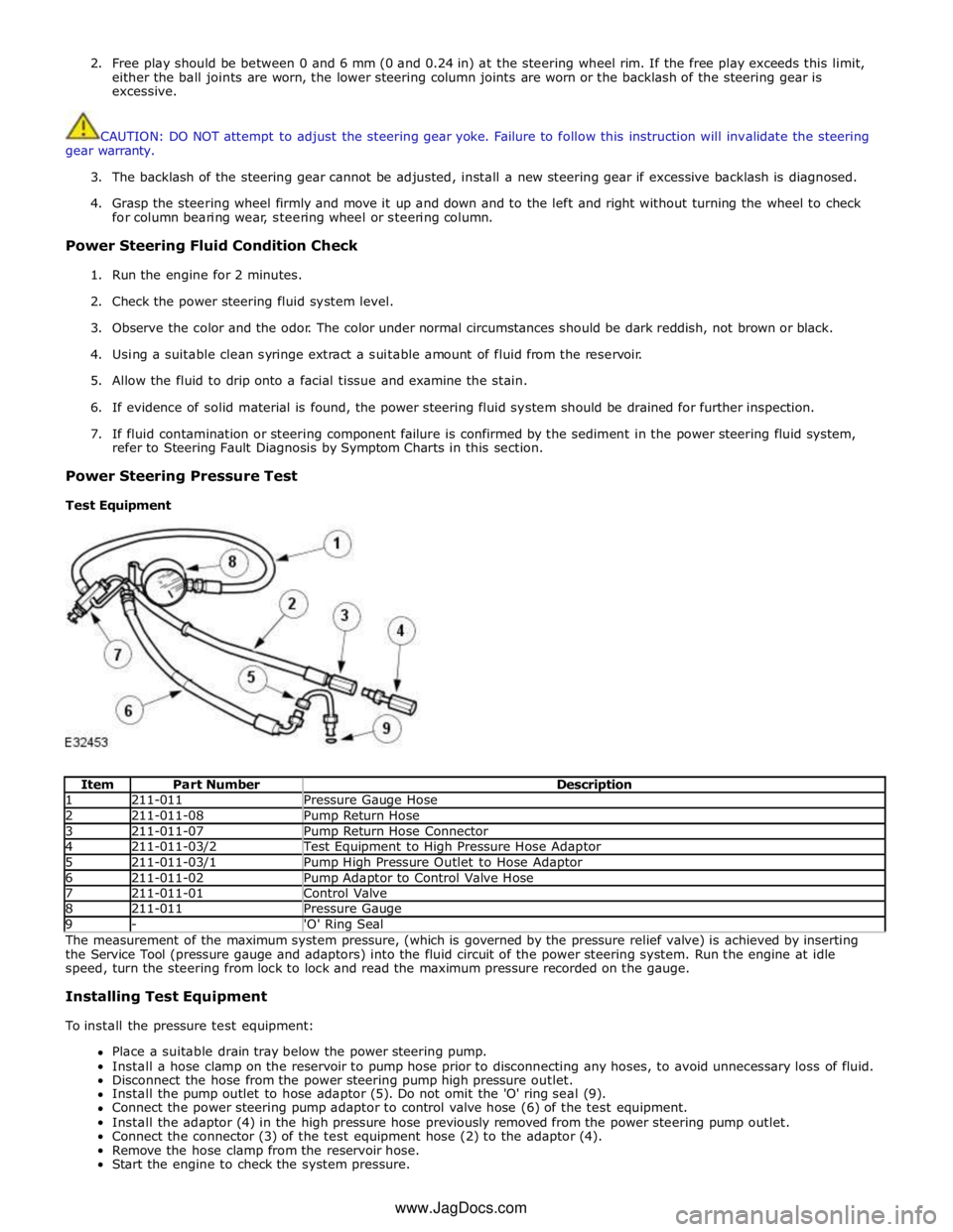
Item Part Number Description 1 211-011 Pressure Gauge Hose 2 211-011-08 Pump Return Hose 3 211-011-07 Pump Return Hose Connector 4 211-011-03/2 Test Equipment to High Pressure Hose Adaptor 5 211-011-03/1 Pump High Pressure Outlet to Hose Adaptor 6 211-011-02 Pump Adaptor to Control Valve Hose 7 211-011-01 Control Valve 8 211-011 Pressure Gauge 9 - 'O' Ring Seal The measurement of the maximum system pressure, (which is governed by the pressure relief valve) is achieved by inserting
the Service Tool (pressure gauge and adaptors) into the fluid circuit of the power steering system. Run the engine at idle
speed, turn the steering from lock to lock and read the maximum pressure recorded on the gauge.
Installing Test Equipment
To install the pressure test equipment:
Place a suitable drain tray below the power steering pump.
Install a hose clamp on the reservoir to pump hose prior to disconnecting any hoses, to avoid unnecessary loss of fluid.
Disconnect the hose from the power steering pump high pressure outlet.
Install the pump outlet to hose adaptor (5). Do not omit the 'O' ring seal (9).
Connect the power steering pump adaptor to control valve hose (6) of the test equipment.
Install the adaptor (4) in the high pressure hose previously removed from the power steering pump outlet.
Connect the connector (3) of the test equipment hose (2) to the adaptor (4).
Remove the hose clamp from the reservoir hose.
Start the engine to check the system pressure. www.JagDocs.com
Page 745 of 3039

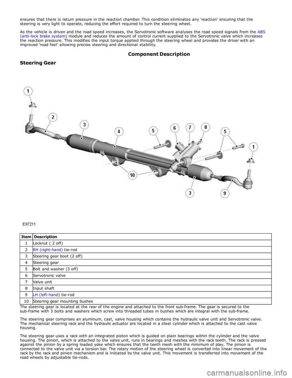
1 Locknut ( 2 off) 2 RH (right-hand) tie-rod 3 Steering gear boot (2 off) 4 Steering gear 5 Bolt and washer (3 off) 6 Servotronic valve 7 Valve unit 8 Input shaft 9 LH (left-hand) tie-rod 10 Steering gear mounting bushes The steering gear is located at the rear of the engine and attached to the front sub-frame. The gear is secured to the
sub-frame with 3 bolts and washers which screw into threaded tubes in bushes which are integral with the sub-frame.
The steering gear comprises an aluminum, cast, valve housing which contains the hydraulic valve unit and Servotronic valve.
The mechanical steering rack and the hydraulic actuator are located in a steel cylinder which is attached to the cast valve
housing.
The steering gear uses a rack with an integrated piston which is guided on plain bearings within the cylinder and the valve
housing. The pinion, which is attached to the valve unit, runs in bearings and meshes with the rack teeth. The rack is pressed
against the pinion by a spring loaded yoke which ensures that the teeth mesh with the minimum of play. The pinion is
connected to the valve unit via a torsion bar. The rotary motion of the steering wheel is converted into linear movement of the
rack by the rack and pinion mechanism and is initiated by the valve unit. This movement is transferred into movement of the
road wheels by adjustable tie-rods.