2010 JAGUAR XFR oil level
[x] Cancel search: oil levelPage 1441 of 3039

DTC Description Possible Cause Action P0781-07
1-2 Shift - Mechanical
Failures
Gear Ratio Monitoring.
Mechanical Failures Check and correct oil level. Clear DTC. If code
re-detects suspect Transmission (Gearbox) internal
fault. Install a new Transmission as required, refer to
the new module/component installation note at the top of the DTC Index P0781-77
2-1 Shift - commanded
position not reachable
Gear Ratio Monitoring.
Mechanical Failures Check and correct oil level. Clear DTC. If code
re-detects suspect Transmission (Gearbox) internal
fault. Install a new Transmission as required, refer to
the new module/component installation note at the top of the DTC Index P0782-07
2-3 Shift - commanded
position not reachable
Gear Ratio Monitoring.
Mechanical Failures Check and correct oil level. Clear DTC. If code
re-detects suspect Transmission (Gearbox) internal
fault. Install a new Transmission as required, refer to
the new module/component installation note at the top of the DTC Index P0782-77
3-2 Shift - commanded
position not reachable
Gear Ratio Monitoring.
Mechanical Failures Check and correct oil level. Clear DTC. If code
re-detects suspect Transmission (Gearbox) internal
fault. Install a new Transmission as required, refer to
the new module/component installation note at the top of the DTC Index P0783-07
3-4 Shift - Mechanical
Failures
Gear Ratio Monitoring.
Mechanical Failures Check and correct oil level. Clear DTC. If code
re-detects suspect Transmission (Gearbox) internal
fault. Install a new Transmission as required, refer to
the new module/component installation note at the top of the DTC Index P0783-77
3-4 Shift - commanded
position not reachable
Gear Ratio Monitoring.
Mechanical Failures Check and correct oil level. Clear DTC. If code
re-detects suspect Transmission (Gearbox) internal
fault. Install a new Transmission as required, refer to
the new module/component installation note at the top of the DTC Index P0784-07
4-5 Shift - Mechanical
Failures
Gear Ratio Monitoring.
Mechanical Failures Check and correct oil level. Clear DTC. If code
re-detects suspect Transmission (Gearbox) internal
fault. Install a new Transmission as required, refer to
the new module/component installation note at the top of the DTC Index P0784-77
4-5 Shift - commanded
position not reachable
Gear Ratio Monitoring.
Mechanical Failures Check and correct oil level. Clear DTC. If code
re-detects suspect Transmission (Gearbox) internal
fault. Install a new Transmission as required, refer to
the new module/component installation note at the top of the DTC Index P0798-1A
Pressure Control Solenoid C
Electrical - Circuit Resistance
Below Threshold
Pressure control solenoid
C Circuit resistance
below threshold Suspect the Transmission control module. Install a
new Transmission control module as required, refer to
the new module/component installation note at the
top of the DTC Index P0798-1E
Pressure Control Solenoid C
Electrical - Circuit Short to
Ground
Pressure control solenoid
C electrical circuit short
to ground Suspect the Transmission control module. Install a
new Transmission control module as required, refer to
the new module/component installation note at the
top of the DTC Index P0798-21
Pressure Control Solenoid C
Electrical - signal amplitude
< minimum
Pressure Control Solenoid
C Electrical signal
amplitude < minimum Suspect the Transmission control module. Install a
new Transmission control module as required, refer to
the new module/component installation note at the
top of the DTC Index P0814-62 Transmission Range Display
Circuit - signal compare
failure
Transmission Range
Display Circuit signal
compare failure Suspect the Transmission control module. Install a
new Transmission control module as required, refer to
the new module/component installation note at the
top of the DTC Index P0826-08
Up and Down Switch circuit -
Bus Signal Message Failures
Invalid CAN signal from
BCM/Instrument cluster
Stuck switch
CAN bus circuit fault Check Central junction box and Instrument cluster for
stored DTCs. Check gear change switches for correct
operation. Refer to circuit diagrams and check CAN bus
for a circuit fault P0826-81
Up and Down Switch Circuit -
invalid serial data received
Invalid Can signal from
BCM / Instrument cluster
Stuck switch
CAN Bus Circuit fault Check Central junction box and Instrument cluster for
stored DTCs. Check Gear Change Switches for correct
operation. Refer to Circuit diagrams and check CAN
Bus for Circuit fault P0826-88
Up and Down Switch Circuit -
Bus off
SWM to BCM /
Instrument cluster LIN
Bus failure Check Central junction box and Steering Wheel Ice
Switches for stored DTCs. Refer to Circuit diagrams
and check LIN Bus for Circuit fault
Page 1442 of 3039

DTC Description Possible Cause Action P0829-07
5-6 Shift - Mechanical
Failures
Gear Ratio Monitoring.
Mechanical Failures Check and correct oil level. Clear DTC. If code
re-detects suspect Transmission internal fault. Install
a new Transmission as required, refer to the new
module/component installation note at the top of the
DTC Index P0829-77
6-5 Shift - Commanded
Position Not Reachable
Gear Ratio Monitoring.
Mechanical Failures Check and correct oil level. Clear DTC. If code
re-detects suspect Transmission internal fault. Install
a new Transmission as required, refer to the new
module/component installation note at the top of the
DTC Index P084F-01
Park / Neutral Switch Input
Circuit - General Electrical
Failure
Wrong voltage level
detected on Park/No Park
signal Check for correct output at Transmission control
module park signal pin (check in all positions) 12 volts
in Park, 0 volts in all other positions. If fault
identified, suspect the Transmission control module.
Install a new Transmission control module as required,
refer to the new module/component installation note
at the top of the DTC Index. If no fault identified,
check Park signal circuit to Transmission Shift Module
for short, open circuit. P0850-01
Park / Neutral Switch Input
Circuit - General Electrical
Failure
General electrical failure Suspect the Transmission control module. Install a
new Transmission control module as required, refer to
the new module/component installation note at the top of the DTC Index P0850-02
Park / Neutral Switch Input
Circuit - General signal
failure
General signal failure Check park lock mechanism. If park lock operation is
correct, suspect the transmission control module.
Check and install a new transmission control module
as required. Refer to the warranty policy and
procedures manual, or determine if any prior approval
programme is in operation, prior to the installation of
a new module/component P0850-29
Park / Neutral Switch Input
Circuit - signal invalid
Signal invalid Check park lock mechanism. If park lock operation is
correct, suspect the transmission control module.
Check and install a new transmission control module
as required. Refer to the warranty policy and
procedures manual, or determine if any prior approval
programme is in operation, prior to the installation of
a new module/component P850-1C
Park / Neutral Switch Input
Circuit - circuit voltage out
of range
Circuit voltage out of
range Check park lock mechanism, if park lock operation
correct suspect the Transmission control module.
Install a new Transmission control module as required,
refer to the new module/component installation note
at the top of the DTC Index P0919-93
Gear Shift Position Control
Error - no operation
No shifting despite driver
request Suspect the Transmission control module. Install a
new Transmission control module as required, refer to
the new module/component installation note at the top of the DTC Index P0919-94
Gear Shift Position Control
Error - unexpected operation
Shifting without driver
request Suspect the Transmission control module. Install a
new Transmission control module as required, refer to
the new module/component installation note at the top of the DTC Index P0938-29
Hydraulic Oil Temperature
Sensor Range/Performance -
signal invalid
Transmission fluid
temperature compared
with module temperature
fault Clear DTC. Carry out cold start road test, continue
driving vehicle until normal operating temperature is
achieved. Read DTCs, if DTC returns, suspect the
Transmission control module. Install a new
Transmission control module as required, refer to the
new module/component installation note at the top of
the DTC Index P0963-12
Pressure Control Solenoid A
Control Circuit High - Circuit
Short to Battery
Pressure control solenoid
1 Circuit Short to Power Suspect the Transmission control module. Install a
new Transmission control module as required, refer to
the new module/component installation note at the top of the DTC Index P0964-13
Pressure Control Solenoid B
Control Circuit / Open -
Circuit Open
Pressure Control Solenoid
B Control Circuit Open Suspect the Transmission control module. Install a
new Transmission control module as required, refer to
the new module/component installation note at the top of the DTC Index P0964-14
Pressure Control Solenoid B
Control Circuit / Open -
Circuit Short to Ground or
Open
Pressure Control Solenoid
B Control Circuit Short to
Ground or Open Suspect the Transmission control module. Install a
new Transmission control module as required, refer to
the new module/component installation note at the
top of the DTC Index P0966-11
Pressure Control Solenoid B
Control Circuit Low - Circuit
Short to Ground
Pressure control solenoid
2 Circuit Short to Ground Suspect the Transmission control module. Install a
new Transmission control module as required, refer to
the new module/component installation note at the top of the DTC Index www.JagDocs.com
Page 1444 of 3039

DTC Description Possible Cause Action P1707-77 Transfer Case Neutral or
Park/Neutral Indication
Circuit - commanded
position not reachable
Commanded position not
reachable Clear the DTC. Test drive the Vehicle, engaging and
disengaging the parking lock several times. If the DTC
recurs, check parking lock components and replace as
required. If no faulty park lock component is found
Clear DTC and the DTC returns suspect the
Transmission control module. Install a new
Transmission control module as required, refer to the
new module/component installation note at the top of
the DTC Index P2700-07 Transmission Friction
Element A Apply Time
Range/Performance -
Mechanical Failures
Gear Ratio Monitoring.
Mechanical Failures Check and correct oil level. Clear DTC. If code
re-detects suspect Transmission (Gearbox) internal
fault. Install a new Transmission as required, refer to
the new module/component installation note at the top of the DTC Index P2701-07 Transmission Friction
Element B Apply Time
Range/Performance -
Mechanical Failures
Gear Ratio Monitoring.
Mechanical Failures Check and correct oil level. Clear DTC. If code
re-detects suspect Transmission (Gearbox) internal
fault. Install a new Transmission as required, refer to
the new module/component installation note at the top of the DTC Index P2702-07 Transmission Friction
Element C Apply Time
Range/Performance -
Mechanical Failures
Gear Ratio Monitoring.
Mechanical Failures Check and correct oil level. Clear DTC. If code
re-detects suspect Transmission (Gearbox) internal
fault. Install a new Transmission as required, refer to
the new module/component installation note at the top of the DTC Index P2703-07 Transmission Friction
Element D Apply Time
Range/Performance -
Mechanical Failures
Gear Ratio Monitoring.
Mechanical Failures Check and correct oil level. Clear DTC. If code
re-detects suspect Transmission (Gearbox) internal
fault. Install a new Transmission as required, refer to
the new module/component installation note at the top of the DTC Index P2704-07 Transmission Friction
Element E Apply Time
Range/Performance -
Mechanical Failures
Gear Ratio Monitoring.
Mechanical Failures Check and correct oil level. Clear DTC. If code
re-detects suspect Transmission (Gearbox) internal
fault. Install a new Transmission as required, refer to
the new module/component installation note at the top of the DTC Index P2713-04 Pressure Control Solenoid D
- System Internal Failures
System internal failures Suspect the Transmission control module. Install a
new Transmission control module as required, refer to
the new module/component installation note at the top of the DTC Index P2713-48 Pressure Control Solenoid D
- Supervision Software
Failure
Supervision software
failure Suspect the Transmission control module. Install a
new Transmission control module as required, refer to
the new module/component installation note at the top of the DTC Index P2716-22
Pressure Control Solenoid D
Electrical - signal amplitude
> maximum
Pressure Control Solenoid
D Electrical signal
amplitude > maximum Suspect the Transmission control module. Install a
new Transmission control module as required, refer to
the new module/component installation note at the
top of the DTC Index P2716-1A
Pressure Control Solenoid D
Electrical - Circuit Resistance
Below Threshold
Pressure control solenoid
D circuit resistance below
threshold Suspect the Transmission control module. Install a
new Transmission control module as required, refer to
the new module/component installation note at the
top of the DTC Index P2716-1E
Pressure Control Solenoid D
Electrical - Circuit Resistance
Out Of Range
Pressure control solenoid
D circuit resistance out
of range Suspect the Transmission control module. Install a
new Transmission control module as required, refer to
the new module/component installation note at the
top of the DTC Index P2718-14
Pressure Control Solenoid D
Control Circuit / Open -
Circuit Short to Ground or
Open
Pressure control solenoid
D Circuit Short to Ground
or Open Circuit Suspect the Transmission control module. Install a
new Transmission control module as required, refer to
the new module/component installation note at the
top of the DTC Index P2720-11
Pressure Control Solenoid D
Control Circuit Low - Circuit
Short to Ground
Pressure control solenoid
D Circuit Short to Ground Suspect the Transmission control module. Install a
new Transmission control module as required, refer to
the new module/component installation note at the top of the DTC Index P2721-12
Pressure Control Solenoid D
Control Circuit High - Circuit
Short to Battery
Pressure control solenoid
D Circuit Short to Power Suspect the Transmission control module. Install a
new Transmission control module as required, refer to
the new module/component installation note at the top of the DTC Index P2722-04 Pressure Control Solenoid E
- System Internal Failures
Pressure Control Solenoid
E system internal failures Suspect the Transmission control module. Install a
new Transmission control module as required, refer to
the new module/component installation note at the top of the DTC Index
Page 1448 of 3039

DTC Description Possible Cause Action U0416-68
Invalid Data Received From
Vehicle Dynamics Control
Module - event information
Event information brake
information Check Engine control module for stored DTCs. Check
CAN Bus Circuit for fault U0422-68
Invalid Data Received From
Body Control Module - event
information
Event information invalid
Power mode information Check Central junction box for stored DTCs. Check CAN
Bus Circuit for fault U101B-87
Lost Communication With
GSM - Multiple Bus-missing
message
Missing message lost
communication with
Transmission Shift
Module (multiple Bus) Check Transmission Shift Module for stored DTCs.
Refer to Circuit diagrams and check CAN and LIN Bus
for Circuit fault U3000-49
Control Module - internal
electronic failure
Internal electronic failure Suspect the Transmission control module. Install a
new Transmission control module as required, refer to
the new module/component installation note at the top of the DTC Index U3000-4B
Control Module - Circuit
resistance above threshold
Internal electronic failure Check and correct oil level. Check hydraulic flow
through oil cooler and pipe circuit for restriction or
blockage. If no restrictions found, suspect the
Transmission control module. Install a new
Transmission control module as required, refer to the
new module/component installation note at the top of
the DTC Index U3000-81
Control Module - invalid
serial data received
Vehicle or Engine type
signal incorrect from BCM
or incorrect Transmission
control module software
installed Reflash the Transmission control module using the
manufacturer approved process U3001-94
Control Module Improper
Shutdown - unexpected
operation
Control Module Improper
Shutdown (voltage
related) Check Engine control module For Power (generator)
faults. Check Power and Ground Circuit and Battery for
fault. Clear DTCs. Road Test. If DTC reoccurs suspect
the Transmission control module. Install a new
Transmission control module as required, refer to the
new module/component installation note at the top of
the DTC Index
Page 1521 of 3039

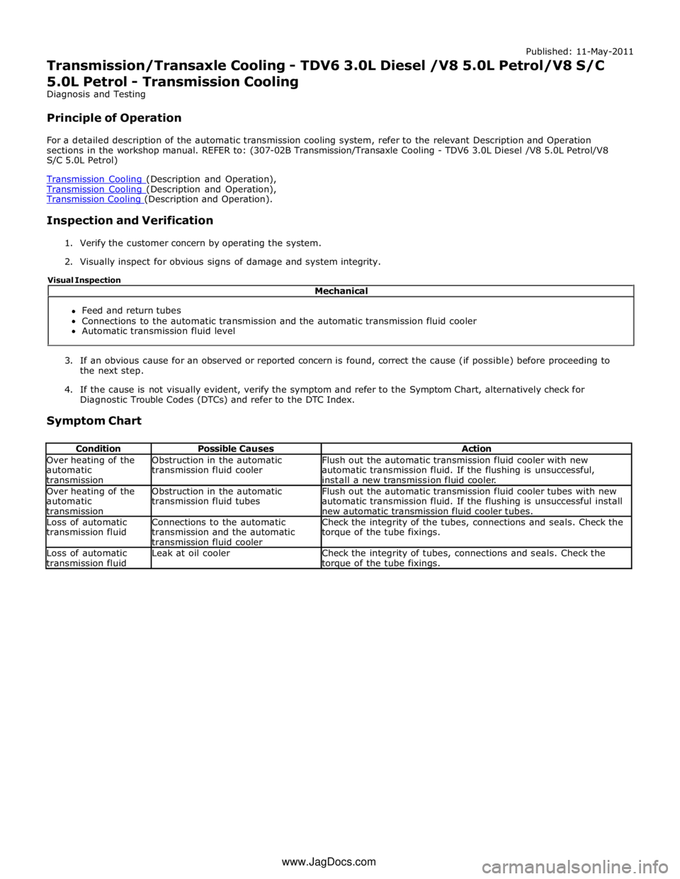
Transmission Cooling (Description and Operation), Transmission Cooling (Description and Operation).
Inspection and Verification
1. Verify the customer concern by operating the system.
2. Visually inspect for obvious signs of damage and system integrity.
3. If an obvious cause for an observed or reported concern is found, correct the cause (if possible) before proceeding to
the next step.
4. If the cause is not visually evident, verify the symptom and refer to the Symptom Chart, alternatively check for
Diagnostic Trouble Codes (DTCs) and refer to the DTC Index.
Symptom Chart
Condition Possible Causes Action Over heating of the
automatic
transmission Obstruction in the automatic
transmission fluid cooler Flush out the automatic transmission fluid cooler with new
automatic transmission fluid. If the flushing is unsuccessful,
install a new transmission fluid cooler. Over heating of the
automatic
transmission Obstruction in the automatic
transmission fluid tubes Flush out the automatic transmission fluid cooler tubes with new
automatic transmission fluid. If the flushing is unsuccessful install
new automatic transmission fluid cooler tubes. Loss of automatic
transmission fluid Connections to the automatic
transmission and the automatic
transmission fluid cooler Check the integrity of the tubes, connections and seals. Check the
torque of the tube fixings. Loss of automatic
transmission fluid Leak at oil cooler
Check the integrity of tubes, connections and seals. Check the torque of the tube fixings. Mechanical
Feed and return tubes
Connections to the automatic transmission and the automatic transmission fluid cooler
Automatic transmission fluid level Visual Inspection
www.JagDocs.com
Page 1590 of 3039

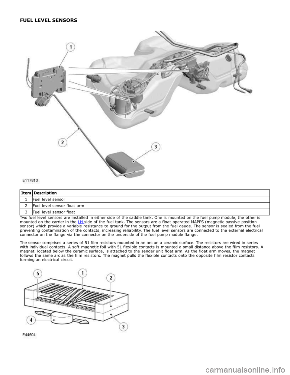
1 Fuel level sensor 2 Fuel level sensor float arm 3 Fuel level sensor float Two fuel level sensors are installed in either side of the saddle tank. One is mounted on the fuel pump module, the other is
mounted on the carrier in the LH side of the fuel tank. The sensors are a float operated MAPPS (magnetic passive position sensor) which provide a variable resistance to ground for the output from the fuel gauge. The sensor is sealed from the fuel
preventing contamination of the contacts, increasing reliability. The fuel level sensors are connected to the external electrical
connector on the flange via the connector on the underside of the fuel pump module flange.
The sensor comprises a series of 51 film resistors mounted in an arc on a ceramic surface. The resistors are wired in series
with individual contacts. A soft magnetic foil with 51 flexible contacts is mounted a small distance above the film resistors. A
magnet, located below the ceramic surface, is attached to the sender unit float arm. As the float arm moves, the magnet
follows the same arc as the film resistors. The magnet pulls the flexible contacts onto the opposite film resistor contacts
forming an electrical circuit.
Page 1591 of 3039

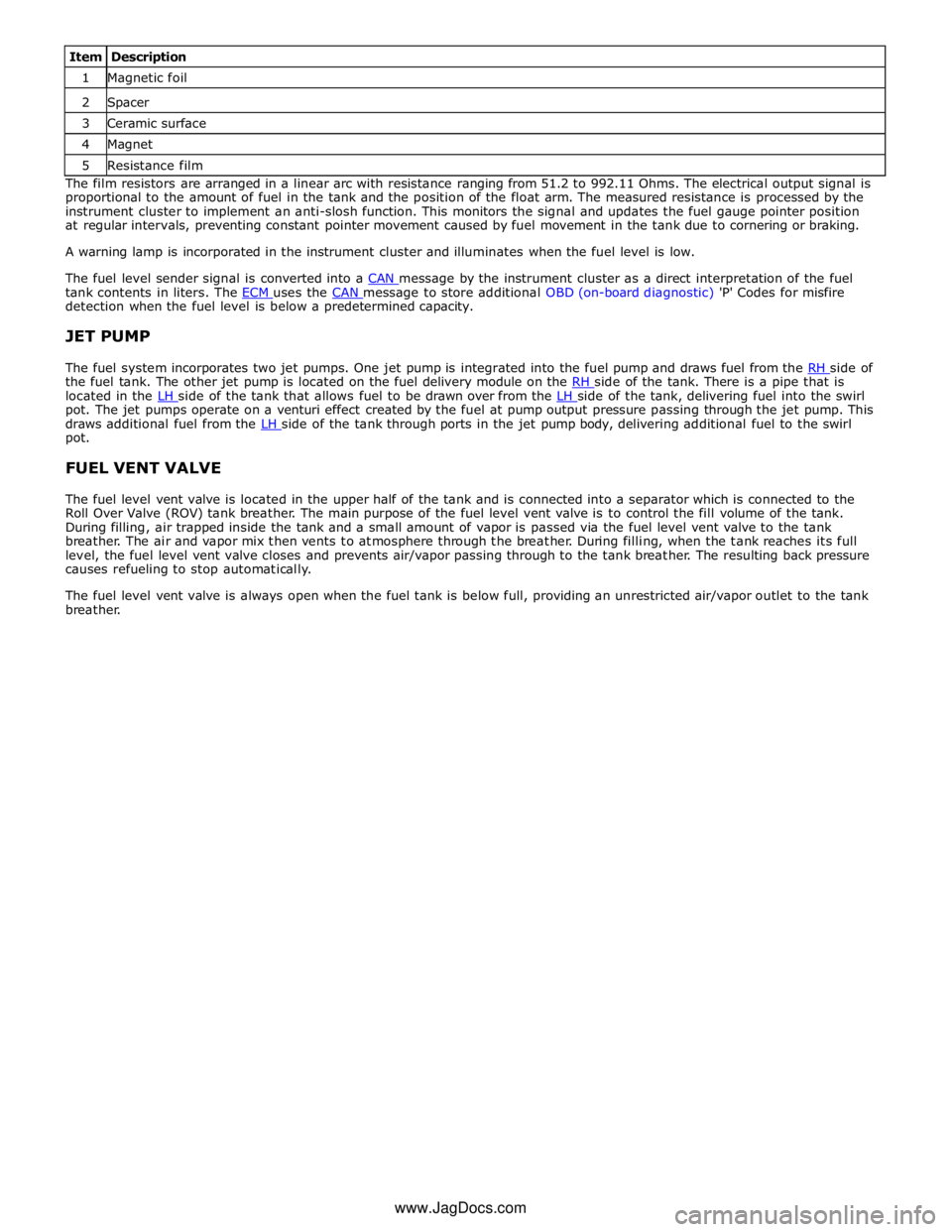
1 Magnetic foil 2 Spacer 3 Ceramic surface 4 Magnet 5 Resistance film The film resistors are arranged in a linear arc with resistance ranging from 51.2 to 992.11 Ohms. The electrical output signal is
proportional to the amount of fuel in the tank and the position of the float arm. The measured resistance is processed by the
instrument cluster to implement an anti-slosh function. This monitors the signal and updates the fuel gauge pointer position
at regular intervals, preventing constant pointer movement caused by fuel movement in the tank due to cornering or braking.
A warning lamp is incorporated in the instrument cluster and illuminates when the fuel level is low.
The fuel level sender signal is converted into a CAN message by the instrument cluster as a direct interpretation of the fuel tank contents in liters. The ECM uses the CAN message to store additional OBD (on-board diagnostic) 'P' Codes for misfire detection when the fuel level is below a predetermined capacity.
JET PUMP
The fuel system incorporates two jet pumps. One jet pump is integrated into the fuel pump and draws fuel from the RH side of the fuel tank. The other jet pump is located on the fuel delivery module on the RH side of the tank. There is a pipe that is located in the LH side of the tank that allows fuel to be drawn over from the LH side of the tank, delivering fuel into the swirl pot. The jet pumps operate on a venturi effect created by the fuel at pump output pressure passing through the jet pump. This
draws additional fuel from the LH side of the tank through ports in the jet pump body, delivering additional fuel to the swirl pot.
FUEL VENT VALVE
The fuel level vent valve is located in the upper half of the tank and is connected into a separator which is connected to the
Roll Over Valve (ROV) tank breather. The main purpose of the fuel level vent valve is to control the fill volume of the tank.
During filling, air trapped inside the tank and a small amount of vapor is passed via the fuel level vent valve to the tank
breather. The air and vapor mix then vents to atmosphere through the breather. During filling, when the tank reaches its full
level, the fuel level vent valve closes and prevents air/vapor passing through to the tank breather. The resulting back pressure
causes refueling to stop automatically.
The fuel level vent valve is always open when the fuel tank is below full, providing an unrestricted air/vapor outlet to the tank
breather.
www.JagDocs.com
Page 1669 of 3039

8. WARNING: Refrigerant must always be recycled before re-use to ensure
that the purity of the refrigerantis high enough for safe use in the air
conditioning system. Recycling should always be carried out with
equipment which is design certified by Underwriter Laboratory Inc. for
compliance with SEA J1991. Other equipment may not recycle refrigerant
to the required level of purity. R143a Refrigerant Recover Recycling
Recharging station must not be used with any other type of
refrigerant.Refrigerant R134a from domestic and comercial sources must
not be used in motor vehicles air conditioning systems.
Allow the system to recover the refrigerant from the system.
9. Close the valves on the refrigerant station.
10. Turn the main switch 'OFF'.
11. Close the valves on the connections.
12. Disconnect the high and low pressure connections.
13. Install the dust covers to the connectors.
14. Open the tap at the rear of the station to drain the refrigerant oil.
15. Measure and record the quantity of refrigerant oil recovered from the
system.
16. Close the tap at the rear of the station.
17. Evacuation.
18. Remove the dust covers from the high and low pressure connections.
19. Connect the high and low pressure lines to the appropriate connections.
20. Open the valves on the connections.
21. Turn the valves on the station to the correct positions.
22. Turn the process switch to the correct position.
23. Turn the main switch to 'ON'.
24. Allow the station to evacuate the A/C system.
25. CAUTION: The system must be evacuated immediatley before
recharging commences. Delay between evacuation and recharging is not
permitted
Recharging
26. Close the valves on the refrigerant station.