2010 JAGUAR XFR oil level
[x] Cancel search: oil levelPage 1710 of 3039
control switch on the integrated control panel or the + and - soft buttons on the touch screen display (TSD). The ATC module also adjusts blower speed to compensate for the ram effect on inlet air produced by forward movement of the vehicle. As
vehicle speed and ram effect increases, blower motor speed is reduced, and vice versa.
Air Distribution Control
Two air distribution doors are used to direct air into the passenger compartment. The doors are operated by stepper motors,
which are controlled by the ATC module using LIN bus messages.
When the A/C system is in automatic mode, the ATC module automatically controls air distribution into the passenger compartment in line with its 'comfort' algorithm. Automatic control is overridden if any of the TSD air distribution soft buttons
are selected. Air distribution in the passenger compartment will remain as selected until the 'Auto' switch is pressed or a
different manual selection is made.
A/C Compressor Control
When A/C is selected the ATC module maintains the evaporator at an operating temperature that varies with the passenger compartment cooling requirements. If the requirement for cooled air decreases, the ATC module raises the evaporator operating temperature by reducing the flow of refrigerant provided by the A/C compressor. The ATC module closely controls the rate of temperature increase to avoid introducing moisture into the passenger compartment.
If the requirement for cooled air increases, the ATC module lowers the evaporator operating temperature by increasing the flow of refrigerant provided by the A/C compressor.
When A/C is off, the compressor current signal supplied by the ATC module holds the A/C compressor solenoid valve in the minimum flow position, effectively switching off the A/C function.
The ATC module incorporates limits for the operating pressure of the refrigerant system. If the system approaches the high pressure limit, the compressor current signal is progressively reduced until the system pressure decreases. If the system falls
below the low pressure limit, the compressor current signal is held at its lowest setting so that the A/C compressor is maintained at its minimum stroke. This avoids depletion of the lubricant from the A/C compressor.
A/C Compressor Torque
The ATC module transmits refrigerant pressure and A/C compressor current values to the ECM (engine control module) over the medium speed then high speed CAN bus, using the CJB as a gateway. The ECM uses these values to calculate the torque being used to drive the A/C compressor. The ECM compares the calculated value with its allowable value and if necessary forces the ATC module to inhibit the A/C compressor by transmitting the 'ACClutchInhibit' CAN message. This forces the ATC module to reduce the drive current to the A/C compressor solenoid valve, which reduces refrigerant flow. This in turn reduces the torque required to drive the A/C compressor.
By reducing the maximum A/C compressor torque, the ECM is able to reduce the load on the engine when it needs to maintain vehicle performance or cooling system integrity.
Cooling Fan Control
The ATC module determines the amount of condenser cooling required from the refrigerant pressure sensor, since there is a direct relationship between the temperature and pressure of the refrigerant. The cooling requirement is broadcast to the ECM on the medium speed CAN bus. The ECM then controls the temperature of the condenser using the cooling fan.
Programmed Defrost
The programmed defrost DEF switch is located on the integrated control panel. When the switch is pressed, the ATC module instigates the programmed defrost function. When selected, the ATC module configures the system as follows:
Automatic mode off.
A/C on. Selected temperature unchanged.
Air inlet set to fresh air.
Air distribution set to windshield.
Blower speed set to level 6.
Windshield heater (where fitted) and rear window heater on.
The programmed defrost function can be cancelled by one of the following:
Selecting any air distribution switch on the TSD.
Pressing the AUTO switch on the integrated control panel.
A second press of the DEF button.
Switching the ignition OFF.
The blower speed can be adjusted without terminating the programmed defrost function.
Rear Window Heater
Rear window heater operation is only enabled when the engine is running. The ATC module controls operation of the rear window heater using a relay in the RJB. When rear window heater operation is required, the ATC module broadcasts a message to the RJB on the medium speed CAN bus. On receipt of the message, the RJB energizes the relay by providing a ground path for the relay coil. This allows a battery feed to flow across the relay to power the rear window heater element.
Page 1711 of 3039
rear window heater switch is pressed or the engine stops.
Automatic operation during a journey is initiated when low ambient air temperatures are experienced and the vehicle has been
travelling for a set period of time above a threshold speed. In this instance, no feedback is given to the driver to inform him
the rear window heater is operational (the switch LED is not illuminated). The duration of heater operation is variable depending on the ambient air temperature, vehicle speed and the amount of time the vehicle has been travelling.
Windshield Heater (Where Fitted)
Windshield heater operation is only enabled when the engine is running. The ATC module controls operation of the windshield heater using two relays in the EJB (engine junction box). When windshield heater operation is required, the ATC module broadcasts a message to the CJB on the medium speed CAN bus. On receipt of the message, the CJB energizes the relays by providing a ground path for both relay coils. This allows a battery feed to flow across the relays to power the windshield left
and right heater elements.
There are two modes of windshield heater operation; manual and automatic.
Manual operation is activated by pressing the windshield heater switch on the integrated control panel. When the switch is
pressed, the status LED in the switch illuminates and the windshield heater elements are energized. Manual operation is discontinued when the windshield heater switch is pressed a second time, 5 minutes have elapsed (the heating phase), or the
engine stops. If manual operation is discontinued by the engine stopping, the previous heating phase is resumed if the engine
is re-started within 30 seconds.
There are two variants of automatic operation; automatic operation at the start of a journey and automatic operation during a
journey.
Automatic operation at the start of a journey is initiated if the ambient air temperature is below 5 °C (41 °F). In this instance,
the switch LED is illuminated and the heater elements are energized for 6.5 minutes. Automatic operation is discontinued if the windshield heater switch is pressed or the engine stops.
Automatic operation during a journey is initiated when low ambient air temperatures are experienced and the vehicle has been
travelling for a set period of time above a threshold speed. In this instance, no feedback is given to the driver to inform him
the windshield heater is operational (the switch LED is not illuminated) and the duration of operation is variable depending upon the ambient air temperature, vehicle speed and the amount of time the vehicle has been travelling.
Exterior Mirror Heaters
Operation of the exterior mirror heaters is fully automatic and not controllable by the driver. Exterior mirror heater operation is
determined by ambient air temperature and windshield wiper status. When ambient air temperature reaches a pre-determined
level, the ATC module broadcasts an exterior mirror heating request to the door modules over the medium speed CAN bus. On receipt of this message, the door modules provide feed and ground connections to both exterior mirror heater elements.
The amount of time the exterior mirror heaters are operational increases if the windshield wipers are switched on. This ensures
the mirrors remain mist free in damp and wet conditions, where there is an increased risk of misting.
Seat Heaters (Where Fitted)
There are four seat heater settings available; off, 1, 2 and 3, which can be selected on the home and climate control screens
of the TSD. The heat setting is relayed to the vehicle occupants through a graduated display on the TSD.
Operation of the heated seats is controlled by the ATC module. When the ATC module receives a heating request from the TSD, it broadcasts a message to the CJB over the medium speed CAN bus. The CJB then provides a hardwired 12 V supply to the three heater elements in the related front seat. The heater elements, two in the seat cushion and one in the seat squab,
are wired in series. The ATC module monitors seat temperature using a temperature sensor located in each seat cushion. The CJB provides the temperature sensors with a 5 V supply. The level of the returned voltage back to the CJB is proportional to the seat temperature. The value of the return signal is broadcast to the ATC module, over the medium speed CAN bus, which allows it to control the seat temperature to the required level. The ATC module will suspend or disable operation of the seat heaters if any of the following occur:
Battery voltage exceeds 16.5 ± 0.3 V for more than 5 seconds. Seat heating is re-enabled when battery voltage
decreases to 16.2 ± 0.3 V.
If a short or open circuit is detected.
If the seat heat temperature rises significantly above the target temperature setting.
The graduated display on the TSD remains illuminated until the seat heaters are turned off or the engine stops. If the engine
is restarted within 30 seconds the seat heater resumes the previous heating level.
Page 1784 of 3039
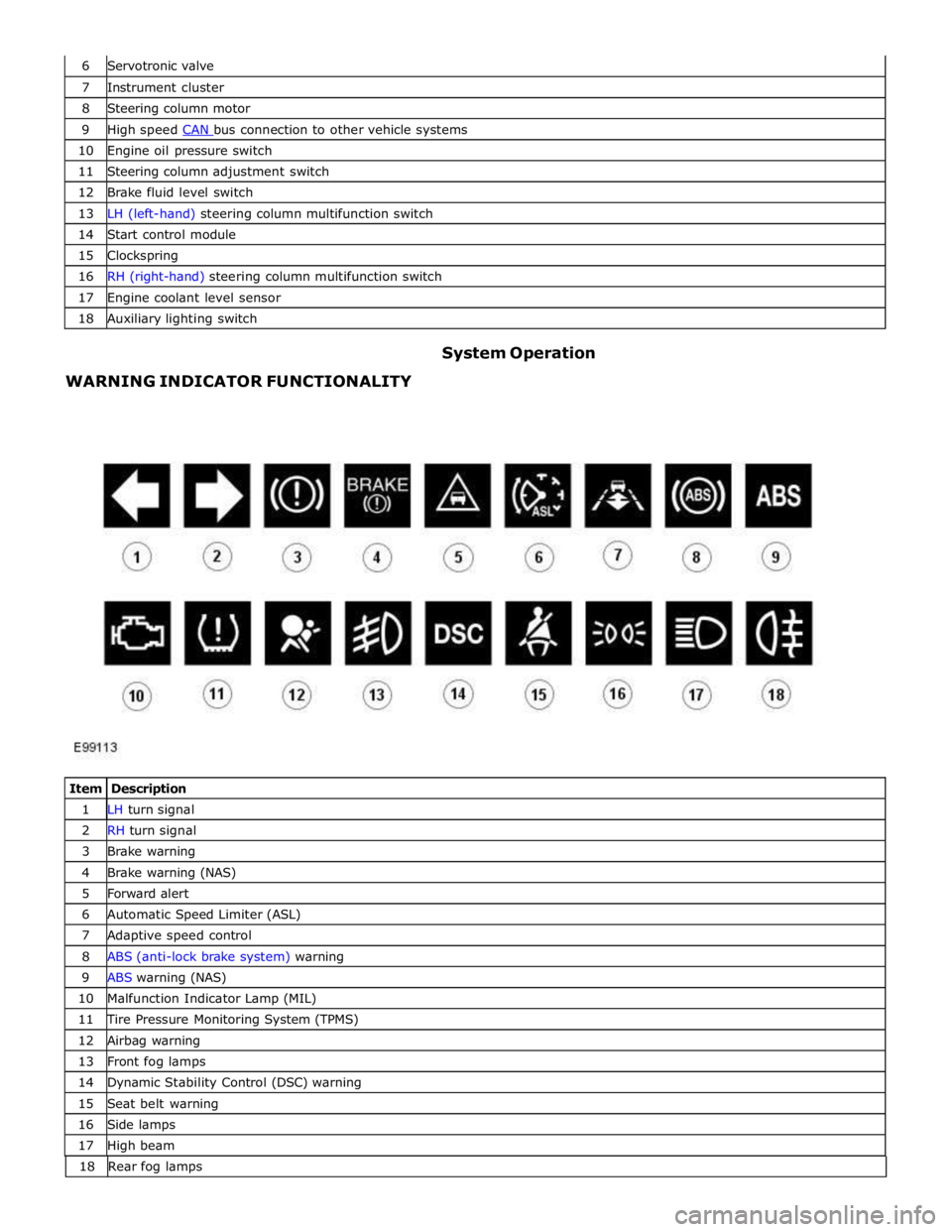
7 Instrument cluster 8 Steering column motor 9 High speed CAN bus connection to other vehicle systems 10 Engine oil pressure switch 11 Steering column adjustment switch 12 Brake fluid level switch 13 LH (left-hand) steering column multifunction switch 14 Start control module 15 Clockspring 16 RH (right-hand) steering column multifunction switch 17 Engine coolant level sensor 18 Auxiliary lighting switch
WARNING INDICATOR FUNCTIONALITY System Operation
Item Description 1 LH turn signal 2 RH turn signal 3 Brake warning 4 Brake warning (NAS) 5 Forward alert 6 Automatic Speed Limiter (ASL) 7 Adaptive speed control 8 ABS (anti-lock brake system) warning 9 ABS warning (NAS) 10 Malfunction Indicator Lamp (MIL) 11 Tire Pressure Monitoring System (TPMS) 12 Airbag warning 13 Front fog lamps 14 Dynamic Stability Control (DSC) warning 15 Seat belt warning 16 Side lamps 17 High beam 18 Rearfoglamps
Page 1825 of 3039
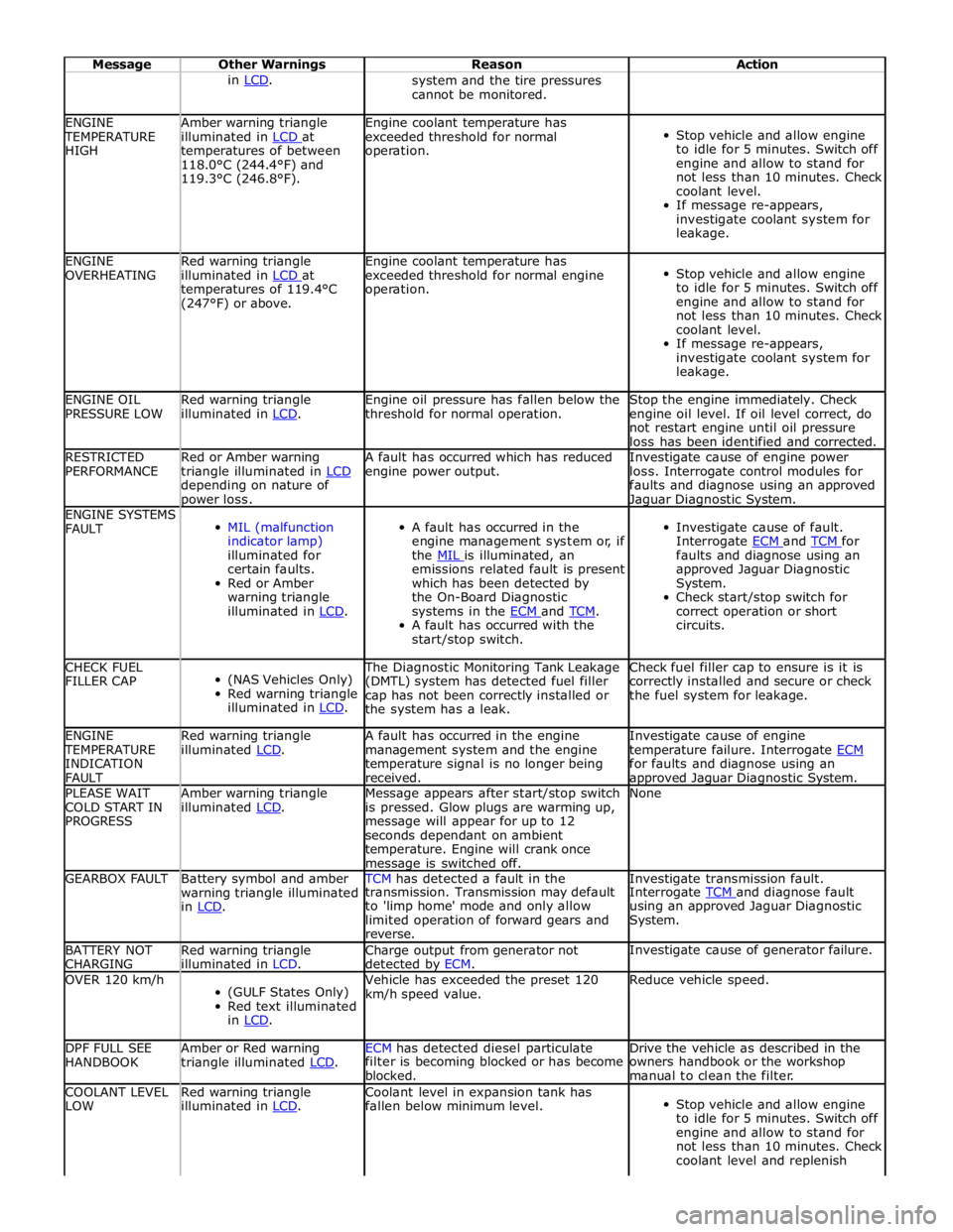
Message Other Warnings Reason Action in LCD. system and the tire pressures
cannot be monitored. ENGINE TEMPERATURE
HIGH Amber warning triangle
illuminated in LCD at temperatures of between
118.0°C (244.4°F) and
119.3°C (246.8°F). Engine coolant temperature has
exceeded threshold for normal
operation.
Stop vehicle and allow engine
to idle for 5 minutes. Switch off
engine and allow to stand for
not less than 10 minutes. Check
coolant level.
If message re-appears,
investigate coolant system for
leakage. ENGINE
OVERHEATING Red warning triangle
illuminated in LCD at temperatures of 119.4°C
(247°F) or above. Engine coolant temperature has
exceeded threshold for normal engine
operation.
Stop vehicle and allow engine
to idle for 5 minutes. Switch off
engine and allow to stand for
not less than 10 minutes. Check
coolant level.
If message re-appears,
investigate coolant system for
leakage. ENGINE OIL
PRESSURE LOW Red warning triangle
illuminated in LCD. Engine oil pressure has fallen below the
threshold for normal operation. Stop the engine immediately. Check
engine oil level. If oil level correct, do
not restart engine until oil pressure
loss has been identified and corrected. RESTRICTED
PERFORMANCE Red or Amber warning
triangle illuminated in LCD depending on nature of power loss. A fault has occurred which has reduced
engine power output. Investigate cause of engine power
loss. Interrogate control modules for
faults and diagnose using an approved Jaguar Diagnostic System. ENGINE SYSTEMS
FAULT
MIL (malfunction
indicator lamp)
illuminated for
certain faults.
Red or Amber
warning triangle
illuminated in LCD.
A fault has occurred in the
engine management system or, if
the MIL is illuminated, an emissions related fault is present
which has been detected by
the On-Board Diagnostic
systems in the ECM and TCM. A fault has occurred with the
start/stop switch.
Investigate cause of fault.
Interrogate ECM and TCM for faults and diagnose using an
approved Jaguar Diagnostic
System.
Check start/stop switch for
correct operation or short
circuits. CHECK FUEL
FILLER CAP
(NAS Vehicles Only)
Red warning triangle
illuminated in LCD. The Diagnostic Monitoring Tank Leakage
(DMTL) system has detected fuel filler
cap has not been correctly installed or
the system has a leak. Check fuel filler cap to ensure is it is
correctly installed and secure or check
the fuel system for leakage. ENGINE TEMPERATURE
INDICATION
FAULT Red warning triangle
illuminated LCD. A fault has occurred in the engine
management system and the engine
temperature signal is no longer being
received. Investigate cause of engine
temperature failure. Interrogate ECM for faults and diagnose using an approved Jaguar Diagnostic System. PLEASE WAIT
COLD START IN
PROGRESS Amber warning triangle
illuminated LCD. Message appears after start/stop switch
is pressed. Glow plugs are warming up,
message will appear for up to 12
seconds dependant on ambient
temperature. Engine will crank once message is switched off. None GEARBOX FAULT
Battery symbol and amber
warning triangle illuminated
in LCD. TCM has detected a fault in the Investigate transmission fault. transmission. Transmission may default
to 'limp home' mode and only allow
limited operation of forward gears and
reverse. Interrogate TCM and diagnose fault using an approved Jaguar Diagnostic
System. BATTERY NOT
CHARGING Red warning triangle
illuminated in LCD. Charge output from generator not
detected by ECM. Investigate cause of generator failure. OVER 120 km/h
(GULF States Only)
Red text illuminated
in LCD. Vehicle has exceeded the preset 120
km/h speed value. Reduce vehicle speed. DPF FULL SEE
HANDBOOK Amber or Red warning
triangle illuminated LCD. ECM has detected diesel particulate Drive the vehicle as described in the filter is becoming blocked or has become
blocked. owners handbook or the workshop
manual to clean the filter. COOLANT LEVEL
LOW Red warning triangle
illuminated in LCD. Coolant level in expansion tank has
fallen below minimum level.
Stop vehicle and allow engine
to idle for 5 minutes. Switch off
engine and allow to stand for
not less than 10 minutes. Check
coolant level and replenish
Page 1828 of 3039
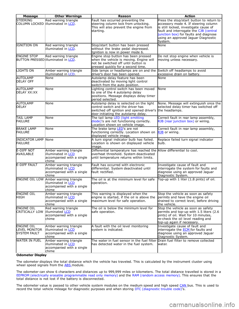
STEERING
COLUMN LOCKED Red warning triangle
illuminated in LCD. Fault has occurred preventing the
steering column lock from unlocking. This will also prevent the engine from
starting. Press the stop/start button to return to
accessory mode 4. If steering column
is still locked, investigate cause of
fault and interrogate the CJB (central junction box) for faults and diagnose
using an approved Jaguar Diagnostic System. IGNITION ON
Red warning triangle
illuminated in LCD. Stop/start button has been pressed
without the brake pedal depressed. Ignition is now in power mode 6. None ENGINE STOP
BUTTON PRESSED Red warning triangle
illuminated in LCD. Engine stop button has been pressed
when the vehicle is moving. Engine will
not be switched off until button is pressed quickly for a second time. Do not stop engine when vehicle is
moving unless necessary. LIGHTS ON
Amber warning triangle
illuminated in LCD. Side lamps or headlamps are on and the
driver's door has been opened. Switch off headlamps to avoid
excessive drain on battery. AUTOLAMP
DELAY OFF None
Autolamp delay feature has been
deactivated by moving light control
switch from the auto position. None AUTOLAMP
DELAY XX:XX None
Lighting control switch has been moved
to one of the 4 autolamp delay
positions. Message displays delay timer period selected. None AUTOLAMP
DELAY None
Autolamp delay is selected on the light
control switch and the driver has
switched off ignition and opened driver's
door initiating the autolamp delay. None. Message will extinguish once the
selected delay timer has switched off
the headlamps. TAIL LAMP
FAILURE None The tail lamp LED (light emitting
diode)'s are not functioning correctly.
Location shown on vehicle image. Correct fault in rear lamp assembly,
RJB (rear junction box) or wiring. BRAKE LAMP
FAILURE None The brake lamp LED's are not functioning correctly. Location shown on displayed vehicle image. Correct fault in rear lamp assembly,
RJB or wiring. INDICATOR LAMP
FAILURE None
A turn signal indicator bulb has failed.
Location is shown on displayed vehicle image. Replace failed turn signal indicator
bulb. E-DIFF NOT
AVAILABLE Amber warning triangle
illuminated in LCD accompanied with a single
chime Differential temperature has reached the
overheat threshold. System deactivated
until temperature returns within limits. Allow differential to cool. E-DIFF FAULT
Amber warning triangle
illuminated in LCD accompanied with a single
chime Fault has occurred with electronic
differential. System deactivated until
fault rectified. Investigate cause of fault and
interrogate the system for faults and
diagnose using an approved Jaguar Diagnostic System. ENGINE OIL LOW
Amber warning triangle
illuminated in LCD accompanied with a single
chime The oil is at the minimum level for safe
operation. Top-up with 1 liter (1.8 pints) of oil. ENGINE OIL
HIGH Amber warning triangle
illuminated in LCD accompanied with a single
chime This warning is displayed when the
engine is started, if the oil is above the
maximum level for safe operation. Stop the vehicle as soon as safety
permits and have the engine oil
drained to correct level, before driving
the vehicle. ENGINE OIL
CRITICALLY LOW Red warning triangle
illuminated LCD accompanied with a single
chime The oil is below the minimum level for
safe operation. Stop the vehicle as soon as safety
permits and top-up with 1.5 liters (2.6
pints) of oil. Wait for 10 minutes,
re-check the oil level reading and top-up again if necessary. ENGINE OIL
LEVEL MONITOR
SYSTEM FAULT Amber warning triangle
illuminated in LCD accompanied with a single
chime A fault with the oil level monitoring
system is indicated. Investigate cause of fault and
interrogate the ECM for faults and diagnose using an approved Jaguar Diagnostic System. WATER IN FUEL
Amber warning triangle
illuminated in LCD accompanied with a single
chime The water in fuel sensor in the fuel filter
has detected water in the fuel system. Drain fuel filter to remove collected
water. Odometer Display
The odometer displays the total distance which the vehicle has traveled. This is calculated by the instrument cluster using
wheel speed signals from the ABS module.
The odometer can show 6 characters and distances up to 999,999 miles or kilometers. The total distance travelled is stored in a
EEPROM (electrically erasable programmable read only memory) and the RAM (random access memory). This ensures that the
total distance is not lost if the battery is disconnected.
The odometer value is passed to other vehicle system modules on the medium speed and high speed CAN bus. This is used to record the total vehicle mileage for diagnostic purposes and when storing DTC (diagnostic trouble code)'s.
Page 2537 of 3039
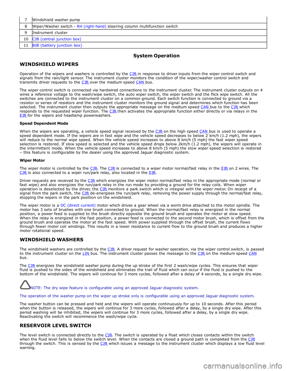
7 Windshield washer pump 8 Wiper/Washer switch - RH (right-hand) steering column multifunction switch 9 Instrument cluster 10 CJB (central junction box) 11 BJB (battery junction box)
WINDSHIELD WIPERS System Operation
Operation of the wipers and washers is controlled by the CJB in response to driver inputs from the wiper control switch and signals from the rain/light sensor. The instrument cluster monitors the condition of the wiper/washer control switch and
transmits driver requests to the CJB over the medium speed CAN bus.
The wiper control switch is connected via hardwired connections to the instrument cluster. The instrument cluster outputs on 4
wires a reference voltage to the wash/wipe switch, the auto wiper switch, the wiper switch and the flick wipe switch. All the
switches are connected to the instrument cluster on a common ground. Each switch function is connected to ground via a
resistor or series of resistors and the instrument cluster monitors the ground signal and determines which function has been
selected. The instrument cluster then outputs the appropriate message on the medium speed CAN bus to the CJB which responds to the requested wiper function. The CJB then activates the appropriate function either directly or via relays in the EJB for the wipers and headlamp powerwashers. Speed Dependent Mode
When the wipers are operating, a vehicle speed signal received by the CJB on the high speed CAN bus is used to operate a speed dependent mode. If the wipers are in fast wipe and the vehicle speed decreases to below 2 km/h (1.2 mph), the wipers
will reduce to the normal wipe speed. When the vehicle speed increases to above 8 km/h (5 mph) the fast wiper speed
selection is restored. If slow speed is selected and the vehicle speed drops below 2km/h (1.2 mph), the wipers will operate in
the intermittent mode. When the vehicle speed increases to above 8 km/h (5 mph) the slow wiper speed selection is restored
– this feature is configurable by the dealer using the approved Jaguar diagnostic system.
Wiper Motor
The wiper motor is controlled by the CJB. The CJB is connected to a wiper motor normal/fast relay in the EJB on 2 wires. The CJB is also connected to a wiper run/park relay, also located in the EJB.
Driver requests are received by the CJB which energizes the wiper motor normal/fast relay in the appropriate mode (normal or fast wipe) and also energizes the run/park relay in the run mode by providing a ground for the relay coils. When wiper
operation is deselected by the driver, the CJB monitors a park switch which is integral with the wiper motor. On receipt of a signal from the park switch, the CJB de-energises the run/park relay, removing the power supply through the normal/fast relay, stopping the wipers in the park position on the windshield.
The wiper motor is a DC (direct current) motor which drives a gear wheel via a worm drive attached to the motor spindle. The
motor has 3 sets of brushes with one brush connected to ground. When the normal/fast relay is energized in the normal
position, a power feed is supplied to the brush directly opposite the ground brush and operates the motor at slow speed.
When the relay is energized in the fast position, a power feed is connected to the second motor brush, which is offset from the
ground brush and operates the motor at the fast speed. With power supplied through the offset brush, the current flows
through fewer motor coil windings. This results in a lower resistance to current flow to the ground brush and produces a higher
motor rotational speed.
WINDSHIELD WASHERS
The windshield washers are controlled by the CJB. A driver request for washer operation, via the wiper control switch, is passed to the instrument cluster on the LIN bus. The instrument cluster passes the message to the CJB on the medium speed CAN bus.
The CJB energizes the windshield washer pump during the up stroke of the first 2 wash/wipe cycles. This ensures that wiper fluid is pushed to the sides of the windshield and eliminates the trail of fluid which can occur if the fluid is pushed to the
bottom of the windshield. The wipers will continue for 3 more cycles, followed after a delay of 4 seconds, by a single dry wipe.
NOTE: The dry wipe feature is configurable using an approved Jaguar diagnostic system.
The operation of the washer pump on the wiper up stroke only is configurable using an approved Jaguar diagnostic system.
The washer button can be pressed and held and the wipers will operate continuously for up to 10 seconds. After this period
when the button is released, the wipers will continue for 3 more cycles, followed after a delay, by a single dry wipe. After this
period washing will be inhibited, the wipers will continue for 3 more cycles, followed after a delay, by a single dry wipe.
Reactivating the switch will recommence the wash/wipe cycle.
RESERVOIR LEVEL SWITCH
The level switch is connected directly to the CJB. The switch is operated by a float which closes contacts within the switch when the fluid level falls to below the switch level. When the contacts are closed a ground path is completed from the CJB through the switch. This is sensed by the CJB which issues a message to the instrument cluster which displays a low fluid level warning.