Page 991 of 3039
Engine - V8 S/C 5.0L Petrol - Oil Pan
Removal and Installation
Removal
NOTE: Removal steps in this procedure may contain installation details. Published: 11-May-2011
1. Refer to: Battery Disconnect and Connect (414-01 Battery, Mounting and Cables, General Procedures).
2. WARNING: Make sure to support the vehicle with axle stands.
Raise and support the vehicle.
3. Refer to: Engine Oil Level Sensor (303-14D Electronic Engine Controls - V8 S/C 5.0L Petrol, Removal and Installation).
4. www.JagDocs.com
Page 992 of 3039
Installation
1. CAUTIONS:
Use only a plastic scraper when removing the sealing
material.
Use lint free cloth.
Make sure that the mating faces are clean and free of
corrosion and foreign material.
Apply RTV sealant WSE-M4G323-A6 (Loctite 5901G)
to the areas shown, and tighten the bolts within 7
minutes.
Apply a bead of sealant, 2.5 mm diameter, to the
area indicated.
2. NOTE: Tighten the bolts in the sequence shown.
Torque: 12 Nm
3. Refer to: Engine Oil Level Sensor (303-14D Electronic Engine Controls - V8 S/C 5.0L Petrol, Removal and Installation).
Page 1080 of 3039

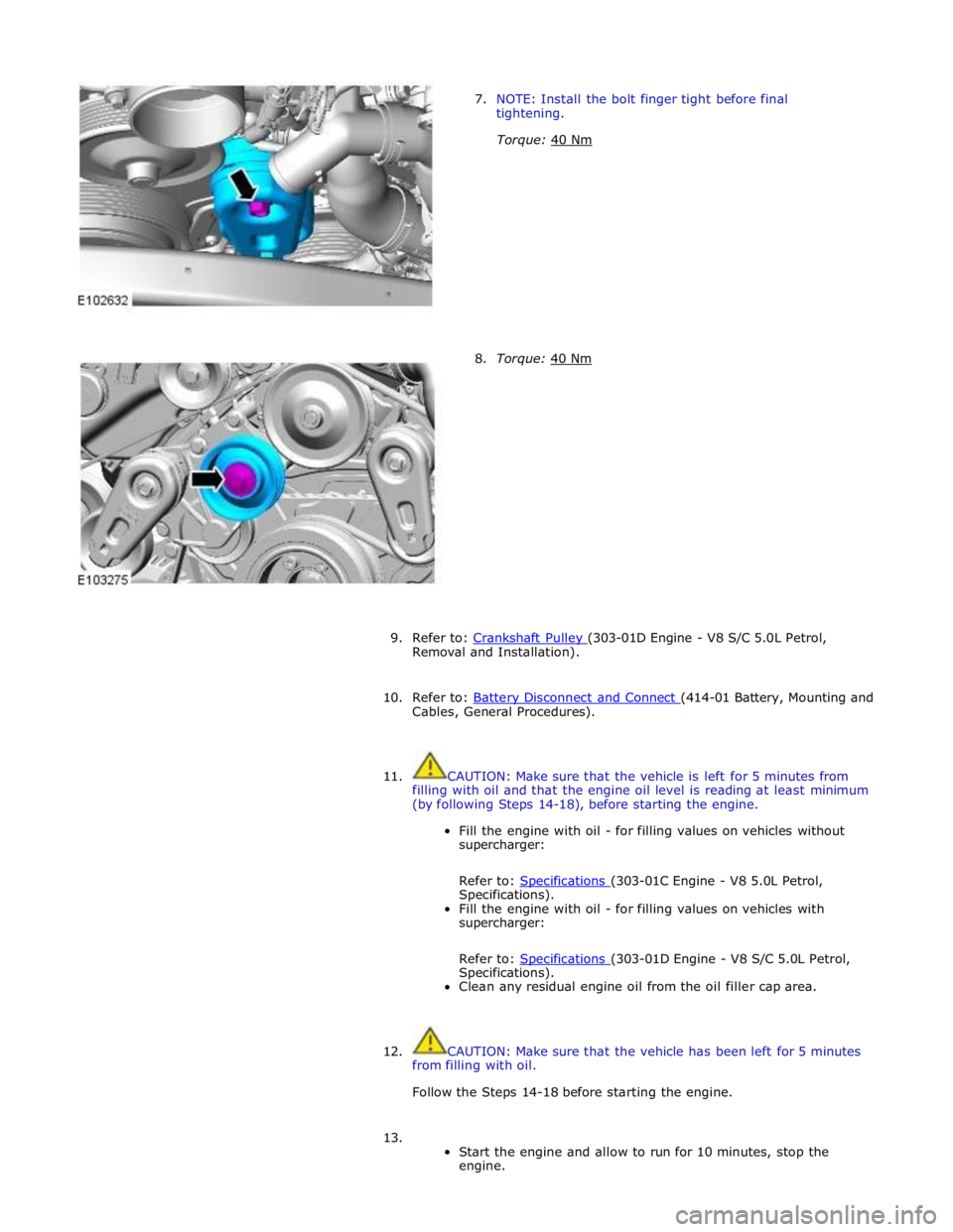
7. NOTE: Install the bolt finger tight before final
tightening.
Torque: 40 Nm
8. Torque: 40 Nm
9. Refer to: Crankshaft Pulley (303-01D Engine - V8 S/C 5.0L Petrol, Removal and Installation).
10. Refer to: Battery Disconnect and Connect (414-01 Battery, Mounting and Cables, General Procedures).
11. CAUTION: Make sure that the vehicle is left for 5 minutes from
filling with oil and that the engine oil level is reading at least minimum
(by following Steps 14-18), before starting the engine.
Fill the engine with oil - for filling values on vehicles without
supercharger:
Refer to: Specifications (303-01C Engine - V8 5.0L Petrol, Specifications).
Fill the engine with oil - for filling values on vehicles with
supercharger:
Refer to: Specifications (303-01D Engine - V8 S/C 5.0L Petrol, Specifications).
Clean any residual engine oil from the oil filler cap area.
12. CAUTION: Make sure that the vehicle has been left for 5 minutes
from filling with oil.
Follow the Steps 14-18 before starting the engine.
13.
Start the engine and allow to run for 10 minutes, stop the
engine.
Page 1081 of 3039
Check for leaks.
14. CAUTIONS:
Make sure that the selector lever and the gearshift mechanism are
in the park (P) position.
Make sure that the hood is open.
Turn the ignition on.
15.
Scroll through the trip menu to access the engine oil
level display. www.JagDocs.com
Page 1082 of 3039
16.
17.
Press the cruise control cancel button twice within 2
seconds.
The message center display will revert to the normal
display in the trip computer.
Scroll through the trip menu to access the engine oil
level display.
Check that the oil level display shows an oil level
reading.
Only after having started and run the engine for 10
minutes (as indicated in Step 13), switch off the
engine, then stabilizing for 10 minutes, take a
reading from the oil level display and, if necessary
top up with engine oil.
18. NOTE: If instructed to follow Steps 14-18 in a previous step, return
to Step 13 and continue the procedure.
Turn the ignition off.
19. Allow 10 minutes for the engine oil level to stabilize if there has been
additional oil top up.
Page 1083 of 3039
20.
NOTE: The following steps are to update the average
oil level value.
Turn the ignition on.
Press and hold the cruise control cancel button for
more than 2 seconds.
21.
The message center display will revert to the normal display in
the trip computer.
22. Turn the ignition off.
23. Turn the ignition on.
24.
Scroll through the trip menu to access the engine oil
level display.
Make sure that the average oil level value has now
been updated.
25. Refer to: Air Deflector (501-02 Front End Body Panels, Removal and Installation).
Page 1114 of 3039

14 Radiator 15 Auxiliary radiator 16 Connection with supercharger cooling system
System Operation
When the engine is running, the coolant is circulated around the engine cooling system by the coolant pump. From the coolant
pump, coolant flows through the cylinder heads and the engine oil cooler into the cylinder block and the heater manifold.
In the cylinder block, the coolant flows forwards to the outlet tube. When the coolant is cold, the thermostat is closed and the
coolant flows direct from the outlet tube back to the coolant pump. Once the coolant reaches operating temperature the
thermostat begins to open, to control system temperature, and coolant flows from the outlet tube to the coolant pump via the
radiator and, on SC (supercharger) vehicles, the auxiliary radiator. When the thermostat is open, the coolant flow through the
radiator(s) also generates a coolant flow through the transmission fluid cooler.
From the heater manifold the coolant flows through the electronic throttle and the heater core, in parallel circuits that are
unaffected by the position of the thermostat. From the electronic throttle, the coolant merges with bleed coolant from the
coolant pump and the outlet tube and flows to the expansion tank. From the heater core, the coolant flows back to the inlet of
the coolant pump.
Expansion and contraction of the coolant is accommodated by an air space in the expansion tank and the compliance of the
flexible hoses.
If the coolant level in the expansion tank decreases below a predetermined value, the level sensor connects a ground to the
instrument cluster, which activates the appropriate warning. For additional information, refer to 413-01 Instrument Cluster.
The cooling fan is operated by a fan control module integrated into the cooling fan motor. The fan control module regulates the
voltage, and thus speed, of the cooling fan motor in response to a PWM (pulse width modulation) signal from the ECM (engine
control module).
The cooling fan receives a battery feed and an ignition feed from the EJB (engine junction box). The ignition feed is supplied
from the main relay in the EJB, which is controlled by the ECM.
The ECM calculates the required fan speed from the engine temperature, A/C (air conditioning) system pressure and transmission fluid temperature. Under hot operating conditions, the fan may continue to operate for 4 minutes after the engine
has been switched off.
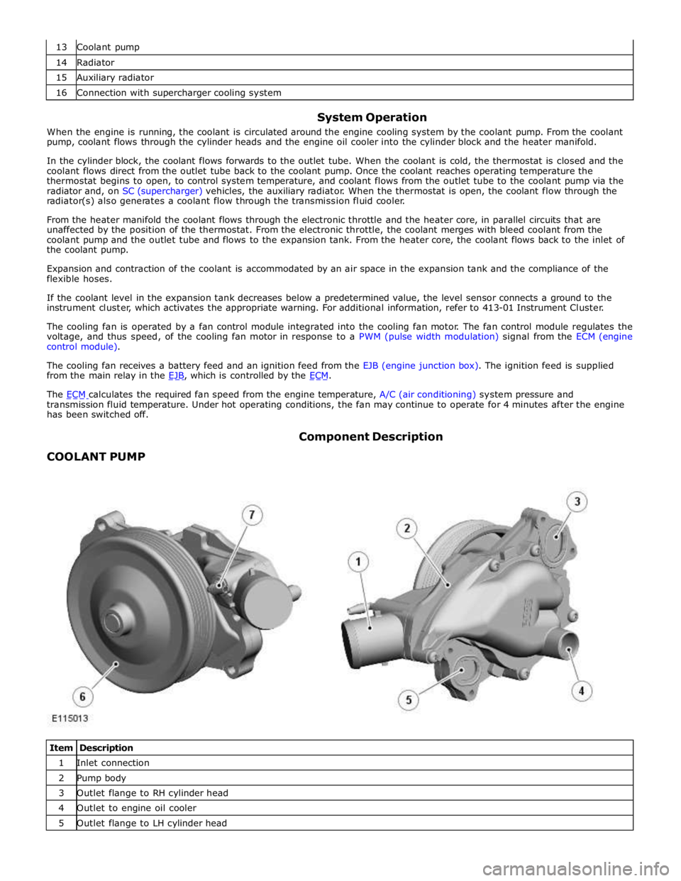
COOLANT PUMP Component Description
Item Description 1 Inlet connection 2 Pump body 3 Outlet flange to RH cylinder head 4 Outlet to engine oil cooler 5 Outlet flange to LH cylinder head
Page 1274 of 3039

GENERAL System Operation
The ignition coils are supplied with electrical power from the battery via a 250 A megafuse in the BJB (battery junction box)
and the ignition relay in the EJB (engine junction box). The control signal for the ignition relay is supplied by the CJB (central
junction box).
The ECM (engine control module) sends a separate signal to each ignition coil to trigger the power stage switching. The ECM calculates the dwell time from the battery voltage and engine speed, to ensure a constant energy level is produced in the
secondary coil each time the power stage is switched. This ensures sufficient spark energy is available without excessive
primary current flow, which avoids overheating and damage to the ignition coils.
The ECM calculates the ignition timing for individual cylinders from: Engine speed
Camshaft position
Engine load
Engine temperature
The knock control function
The shift control function
The idle speed control function.
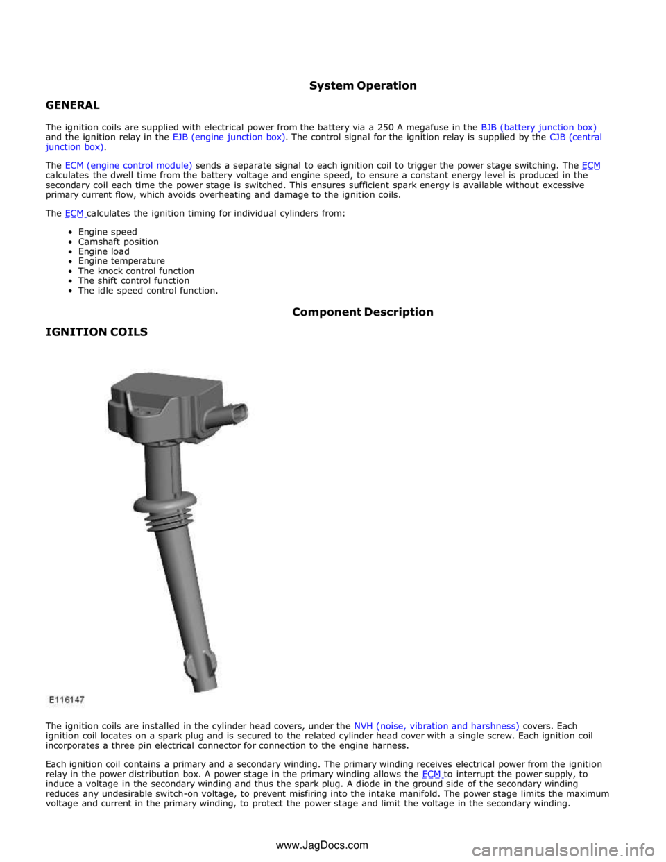
IGNITION COILS Component Description
The ignition coils are installed in the cylinder head covers, under the NVH (noise, vibration and harshness) covers. Each
ignition coil locates on a spark plug and is secured to the related cylinder head cover with a single screw. Each ignition coil
incorporates a three pin electrical connector for connection to the engine harness.
Each ignition coil contains a primary and a secondary winding. The primary winding receives electrical power from the ignition
relay in the power distribution box. A power stage in the primary winding allows the ECM to interrupt the power supply, to induce a voltage in the secondary winding and thus the spark plug. A diode in the ground side of the secondary winding
reduces any undesirable switch-on voltage, to prevent misfiring into the intake manifold. The power stage limits the maximum
voltage and current in the primary winding, to protect the power stage and limit the voltage in the secondary winding. www.JagDocs.com