2010 JAGUAR XFR warning
[x] Cancel search: warningPage 2619 of 3039
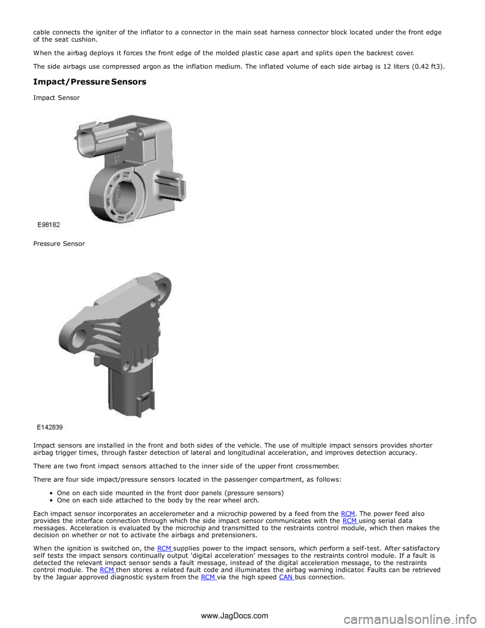
provides the interface connection through which the side impact sensor communicates with the RCM using serial data messages. Acceleration is evaluated by the microchip and transmitted to the restraints control module, which then makes the
decision on whether or not to activate the airbags and pretensioners.
When the ignition is switched on, the RCM supplies power to the impact sensors, which perform a self-test. After satisfactory self tests the impact sensors continually output 'digital acceleration' messages to the restraints control module. If a fault is
detected the relevant impact sensor sends a fault message, instead of the digital acceleration message, to the restraints
control module. The RCM then stores a related fault code and illuminates the airbag warning indicator. Faults can be retrieved by the Jaguar approved diagnostic system from the RCM via the high speed CAN bus connection. www.JagDocs.com
Page 2621 of 3039
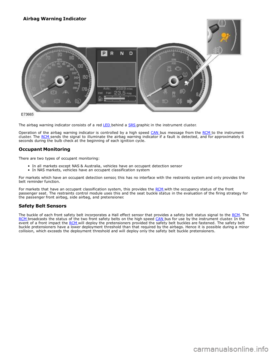
Operation of the airbag warning indicator is controlled by a high speed CAN bus message from the RCM to the instrument cluster. The RCM sends the signal to illuminate the airbag warning indicator if a fault is detected, and for approximately 6 seconds during the bulb check at the beginning of each ignition cycle.
Occupant Monitoring
There are two types of occupant monitoring:
In all markets except NAS & Australia, vehicles have an occupant detection sensor
In NAS markets, vehicles have an occupant classification system
For markets which have an occupant detection sensor, this has no interface with the restraints system and only provides the
belt reminder function.
For markets that have an occupant classification system, this provides the RCM with the occupancy status of the front passenger seat. The restraints control module uses this and the seat buckle status in the evaluation of the firing strategy for
the passenger front airbag, side airbag, and pretensioner.
Safety Belt Sensors
The buckle of each front safety belt incorporates a Hall effect sensor that provides a safety belt status signal to the RCM. The RCM broadcasts the status of the two front safety belts on the high speed CAN bus for use by the instrument cluster. In the event of a front impact the RCM will deploy the pretensioners provided the safety belt buckles are fastened. The safety belt buckle pretensioners have a lower deployment threshold than that required by the airbags. Hence it is possible during a minor
collision, which exceeds the deployment threshold and will deploy only the safety belt buckle pretensioners. Airbag Warning Indicator
Page 2624 of 3039
Published: 10-Jul-2014
Supplemental Restraint System - Air Bag and Safety Belt Pretensioner
Supplemental Restraint System (SRS)
Diagnosis and Testing
Principle of Operation
For a detailed description of the supplemental restraints system and operation, refer to the relevant Description and Operation
section in the workshop manual. REFER to: (501-20B Supplemental Restraint System)
Air Bag and Safety Belt Pretensioner Supplemental Restraint System (SRS) (Description and Operation), Air Bag and Safety Belt Pretensioner Supplemental Restraint System (SRS) (Description and Operation), Air Bag and Safety Belt Pretensioner Supplemental Restraint System (SRS) (Description and Operation).
Inspection and Verification
WARNING: TO AVOID ACCIDENTAL DEPLOYMENT AND POSSIBLE PERSONAL INJURY, THE BACKUP POWER SUPPLY MUST
BE DEPLETED BEFORE REPAIRING OR REPLACING ANY AIR BAG SUPPLEMENTAL RESTRAINT SYSTEM (SRS) COMPONENTS. TO
DEPLETE THE BACKUP POWER SUPPLY ENERGY, DISCONNECT THE BATTERY GROUND CABLE AND WAIT ONE MINUTE. FAILURE
TO FOLLOW THIS INSTRUCTION MAY RESULT IN PERSONAL INJURY.
CAUTION: Diagnosis by substitution from a donor vehicle is NOT acceptable. Substitution of control modules does not
guarantee confirmation of a fault, and may also cause additional faults in the vehicle being tested and/or the donor vehicle.
NOTE: Given the legal implications of a restraints system failure, harness repairs to Air Bag module circuits are not
acceptable. Where the text refers to "REPAIR the circuit", this will normally mean the replacement of a harness.
1. Verify the customer concern.
2. Visually inspect for obvious signs of damage and system integrity.
3. If an obvious cause for an observed or reported concern is found, correct the cause (if possible) before proceeding to
the next step.
4. If the cause is not visually evident, check for Diagnostic Trouble Codes (DTCs) and refer to the DTC Index.
DTC Index
For a list of Diagnostic Trouble Codes (DTCs) that could be logged on this vehicle, please refer to Section 100-00.
REFER to: Diagnostic Trouble Code (DTC) Index - DTC: Restraints Control Module (RCM) (100-00 General Information, Description and Operation). Electrical
Battery condition, state of charge
Make sure all electrical connector(s) are engaged correctly on the air bag circuits
Wiring harness
Air bag module(s)
Make sure the restraints control module (RCM) is correctly installed
Fuse(s)
Sensor(s)
Pretensioner(s)
Warning lamp bulb(s) Visual Inspection
www.JagDocs.com
Page 2625 of 3039
Supplemental Restraint System - Air Bag Disposal
General Procedures
Deployed Air Bag Published: 11-May-2011
1. WARNING: Always wear safety glasses when repairing an air bag
supplemental restraint system (SRS) vehicle and when handling an air
bag module. Failure to follow this instruction may result in personal
injury.
Deployed air bag modules are to be disposed of as special waste and
must comply with local environmental requirements, if in doubt, contact
Authority for disposal requirements.
2. NOTE: The storage, transportation, disposal, and/or recycling of air
bag module components must be carried out in accordance with all
applicable federal, state and local regulations including, but not limited
to, those governing building and fire codes, environmental protection,
occupational health and safety, and transportation.
Modules removed and deployed by Jaguar service are to be returned to
the importer for disposal.
Undeployed Air Bag — Inoperative
1. WARNING: Carry a live air bag module with the air bag and trim
cover or deployment door pointed away from your body. This will reduce
the risk of injury in the event of an accidental deployment. Failure to
follow this instruction may result in personal injury.
NOTE: All inoperative air bag modules have been placed on the
Mandatory Return List. All discolored or damaged air bag modules must
be treated the same as any inoperative live air bag being returned.
Failure to follow this instruction may result in personal injury.
Remove the inoperative driver air bag module or passenger air bag
module. For additional information Driver Air Bag Module or Passenger Air Bag Module in this section.
Remote Deployment Undeployed Air Bag — Scrapped Vehicle
1. WARNINGS:
Always wear safety glasses when repairing an air bag supplemental
restraint system (SRS) vehicle and when handling an air bag module.
Failure to follow this instruction may result in personal injury.
Carry a live air bag module with the air bag and trim cover or
deployment door pointed away from your body. This will reduce the risk
of injury in the event of an accidental deployment. Failure to follow this
instruction may result in personal injury.
Remote deployment is to be carried out outdoors with all personnel
at least 6.1 meters (20 feet) away to ensure personal safety. Due to the
loud report which occurs when the air bag is deployed, hearing protection
is required. Failure to follow this instruction may result in personal
injury.
Page 2626 of 3039
Do not place the driver or passenger air bag module with the trim
cover or deployment door facing down, as the forces of the deploying air
bag can cause it to ricochet and cause personal injury. Failure to follow
this instruction may result in personal injury.
Equipment required: Universal deployment tool-Part N° 418-135 and 12V
Battery.
2. The deployment procedure should be carried out outdoors away from
other personnel.
3. Remove any loose debris from around air bag. Make sure that no
flammable liquids are present.
4. Disconnect the battery ground and positive cables.
5. Disconnect the relevant air bag module electrical connector.
6. Connect the appropriate adaptor lead to the restraint device.
7. Connect the deployment lead to the adaptor lead. Pass wire of the
deployment tool through window, close all doors, leave window with lead
for deployment tool open.
8. WARNING: Before proceeding, make sure precautions have been taken
to warn personnel of a possible loud noise upon activation. Do not allow
anybody to approach closer to restraint device than six meters. Failure
to follow this instruction may result in personal injury.
Move as far from restraint device as possible and connect the tool clips
to a 12V vehicle battery.
9. WARNING: Do not handle the deployed device immediately after
activation - it may be hot. Allow the unit to cool for at least 20 minutes.
Cooling modules should be continuously monitored to make sure heat
does not create a fire with spilled liquids or other debris. Failure to
follow this instruction may result in personal injury.
Deploy the module by depressing both switches on the tool. If activation
does not occur, disconnect battery from tool and seek advise from Jaguar
Engineering and wait for further instructions.
10. Repeat procedure for all air bags in vehicle.
11. The vehicle is now to be scrapped in the normal manner with modules
installed.
Disposal of live air bag modules for all air bags, using tyres
1. Equipment required: Deployment tool 418-S135, Battery (12V), Safety
goggles to BS2092 grade 2, Rubber gloves to PrEN 374 class 2, Ear
protectors that have been measured to BS.EN 24869, Particulate
respirator to EN 149 grade FFP2S
2. The deployment procedure should be carried out outdoors, away from
other personnel.
3. Stack four scrap tyres, securing together with heavy gauge wire or cable.
Page 2627 of 3039
while disconnected from any electrical power source, connect deployment
harness and place air bag adaptor portion under tyre stack, ready for
connection to air bag.
4. WARNING: Power must not be connected during this step. Failure to
follow this instruction may result in personal injury.
CAUTION: Make sure the connector is not in contact with the
inflator or it will be damaged during the test.
Connect air bag to air bag connector, make sure the locking sleeve is
fully engaged. position the air bag with the cover facing upwards.
5. Make sure battery connections of deployment harness are ten meters
away from the tyre stack
6. Remove any loose from around the air bag . Make sure that no
flammable liquids are present.
7. WARNING: Before proceeding, make sure precautions have been taken
to warn personnel of a possible loud noise upon activation. Do not allow
anybody to approach closer to restraint device than six meters. Failure
to follow this instruction may result in personal injury.
Move as far from restraint device as possible and connect the tool clips
to a 12V vehicle battery.
8. WARNING: Do not handle the deployed device immediately after
activation - it may be hot. Allow the unit to cool for at least 20 minutes.
Cooling modules should be continuously monitored to make sure heat
does not create a fire with spilled liquids or other debris. Failure to
follow this instruction may result in personal injury.
Deploy the module by depressing both switches on the tool. If activation
does not occur, disconnect battery from tool and seek advise from Jaguar
Engineering and wait for further instructions.
9. Allow the air bag to cool for at least 20 minutes. Cooling modules should
be continuously monitored to make sure heat generated a fire with
spilled liquids or other debris.
10. Remove the air bag from the tyre stack and seal in a plastic bag, ready
for disposal.
11. In the event of any problems or queries arising from this procedure,
contact Jaguar Engineering.
Page 2628 of 3039
Supplemental Restraint System - B-Pillar Side Impact Sensor
Removal and Installation
Removal
NOTE: Removal steps in this procedure may contain installation details. Published: 11-May-2011
1. Make the air bag supplemental restraint system (SRS) safe.
Refer to: Standard Workshop Practices (100-00 General Information, Description and Operation).
2. WARNING: To avoid accidental deployment and possible personal injury,
the backup power supply must be depleted before repairing or replacing
any air bag supplementary restraints system (SRS) components. To
deplete the backup power supply energy, disconnect the battery ground
cable and wait for one minute. Failure to follow this instruction may
result in personal injury.
Refer to: Battery Disconnect and Connect (414-01 Battery, Mounting and Cables, General Procedures).
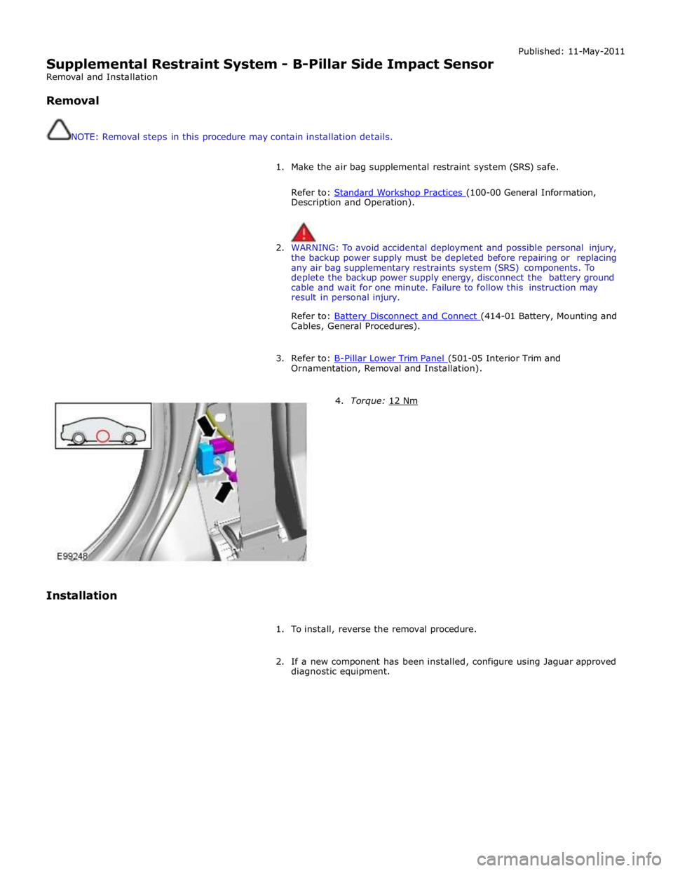
3. Refer to: B-Pillar Lower Trim Panel (501-05 Interior Trim and Ornamentation, Removal and Installation).
Installation
4. Torque: 12 Nm
1. To install, reverse the removal procedure.
2. If a new component has been installed, configure using Jaguar approved
diagnostic equipment.
Page 2629 of 3039
Supplemental Restraint System - Clockspring
Removal and Installation Published: 11-May-2011
Removal
WARNINGS:
Always wear safety glasses when repairing an air bag supplemental restraint system (SRS) vehicle and when handling an
air bag module.
Carry a live air bag module with the air bag and trim cover pointed away from your body. This will reduce the risk of injury
in the event of an accidental deployment. Failure to follow this instruction may result in personal injury.
Do not set a live air bag module down with the trim cover face down. Failure to follow this instruction may result in
personal injury.
After deployment, the air bag surface can contain deposits of sodium hydroxide, a product of the gas generant
combustion that is irritating to the skin. Wash your hands with soap and water afterwards. Failure to follow this instruction
may result in personal injury.
Never probe the connectors on the air bag module. Doing so may result in air bag deployment, which may result in
personal injury. Failure to follow this instruction may result in personal injury.
Air bag modules with discolored or damaged trim covers must be replaced, not repainted.
Vehicle sensor orientation is critical for correct system operation. If a vehicle equipped with an air bag supplemental
restraint system (SRS) is involved in a collision, inspect the sensor mounting bracket and wiring pigtail for deformation. If
damaged, replace the sensor whether or not the air bag is deployed.
To avoid accidental deployment and possible personal injury, the backup power supply must be depleted before repairing
or replacing any air bag supplemental restraint system (SRS) components. To deplete the backup power supply energy,
disconnect the battery ground cable and wait one minute. Failure to follow this instruction may result in personal injury.
CAUTION: Make sure the wheels are in the straight-ahead position. Failure to follow this instruction may result in
damage to the component.
NOTE: Removal steps in this procedure may contain installation details.
1. Make the SRS system safe.
Refer to: Standard Workshop Practices (100-00 General Information, Description and Operation).
2. CAUTIONS:
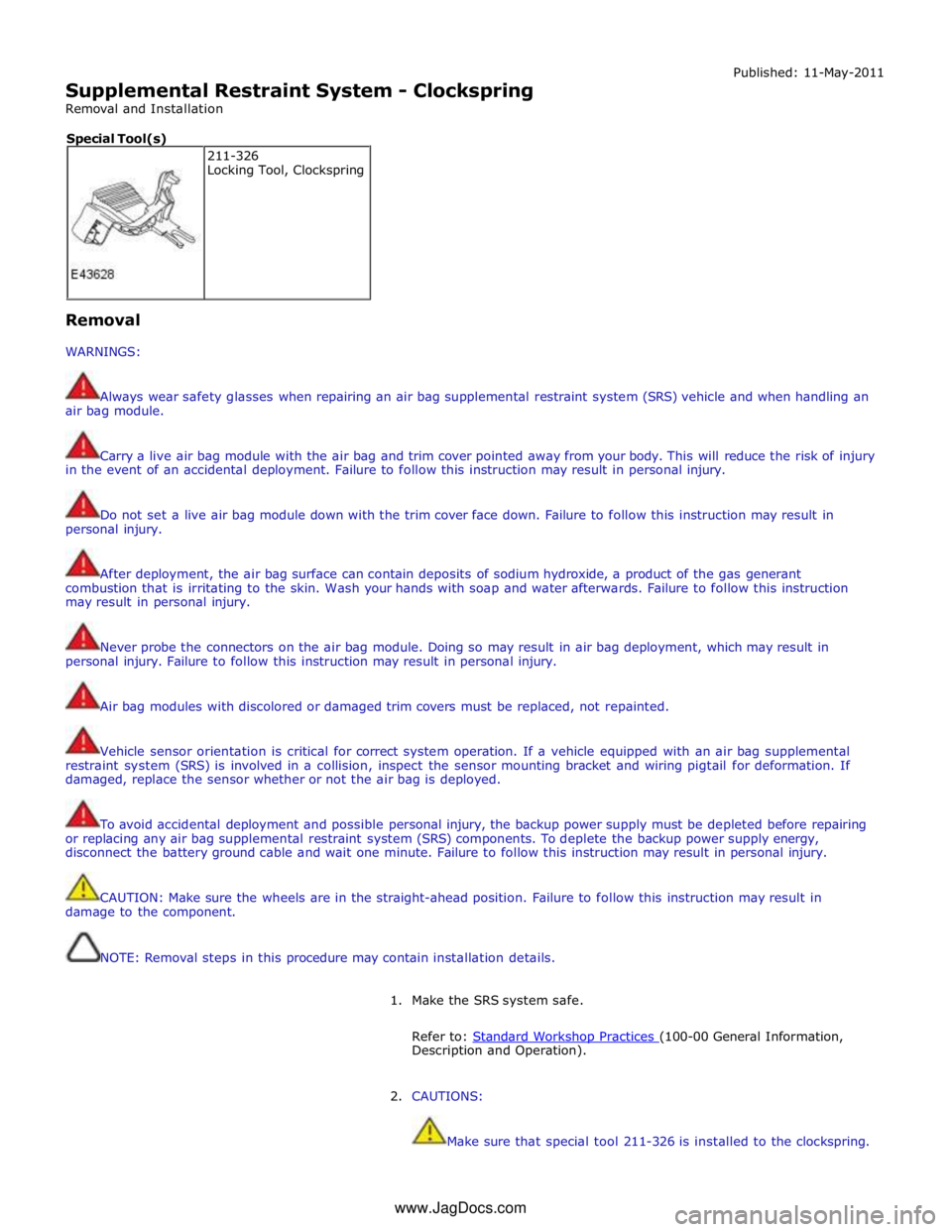
Make sure that special tool 211-326 is installed to the clockspring. 211-326
Locking Tool, Clockspring Special Tool(s)
www.JagDocs.com