Page 2197 of 3039

Front End Body Panels - Hood
Removal and Installation Published: 11-May-2011
Removal
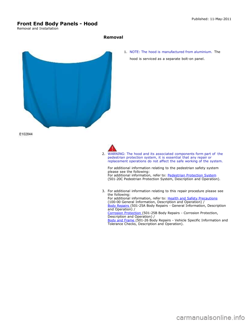
1. NOTE: The hood is manufactured from aluminium. The
hood is serviced as a separate bolt-on panel.
2. WARNING: The hood and its associated components form part of the
pedestrian protection system, it is essential that any repair or
replacement operations do not affect the safe working of the system.
For additional information relating to the pedestrian safety system
please see the following:
For additional information, refer to: Pedestrian Protection System (501-20C Pedestrian Protection System, Description and Operation).
3. For additional information relating to this repair procedure please see
the following:
For additional information, refer to: Health and Safety Precautions (100-00 General Information, Description and Operation) /
Body Repairs (501-25A Body Repairs - General Information, Description and Operation) /
Corrosion Protection (501-25B Body Repairs - Corrosion Protection, Description and Operation) /
Body and Frame (501-26 Body Repairs - Vehicle Specific Information and Tolerance Checks, Description and Operation).
Page 2202 of 3039
Front End Body Panels - Radiator Splash Shield Removal and Installation
Removal Published: 11-May-2011
1. WARNING: Make sure to support the vehicle with axle stands.
Raise and support the vehicle.
2. Installation
1. To install, reverse the removal procedure.
Page 2216 of 3039
Body Closures - Fuel Filler Door Assembly
Removal and Installation
Removal
CAUTION: Do not align the bowl using the hinge arm.
NOTE: Removal steps in this procedure may contain installation details. Published: 11-May-2011
1. WARNING: Do not work on or under a vehicle supported only by a jack.
Always support the vehicle on safety stands.
Raise and support the vehicle.
2. Refer to: Fuel Tank Filler Pipe (310-01, Removal and Installation).
3.
4.
Page 2233 of 3039
10.
11. WARNING: Failure to follow this instruction may cause
damage to the vehicle.
CAUTION: Make sure the locating dowels are installed
correctly.
CAUTION: Make sure that these components are
installed to the noted removal position.
1. To install, reverse the removal procedure. Installation
Page 2257 of 3039
17.
18.
19.
WARNING: This step requires the aid of another
technician.
WARNING: This step requires the aid of another
technician.
CAUTIONS:
Note the fitted position of the component prior to
removal.
Make sure that these components are installed to the
noted removal position.
Page 2258 of 3039
Installation
20.
21.
CAUTION: Note the fitted position of the component
prior to removal.
NOTE: Make sure that the component is installed to
the position noted on removal.
WARNING: This step requires the aid of another
technician.
1. To install, reverse the removal procedure.
Page 2287 of 3039
Exterior Trim and Ornamentation - Rocker Panel Moulding
Removal and Installation
Removal
CAUTIONS:
Protect the surrounding paintwork to avoid damage.
LH illustration shown, RH is similar.
NOTE: Removal steps in this procedure may contain installation details. Published: 04-Mar-2014
1. WARNING: Make sure to support the vehicle with axle stands.
Raise and support the vehicle.
2.
Page 2292 of 3039

Rear View Mirrors - Rear View Mirrors - Overview
Description and Operation
Overview
The exterior mirrors incorporate the following:
Blind spot monitoring indicator
Auto dimming function
Turn signal indicators
Approach lamps
Exterior temperature sensor
Heated mirror function
Reverse dipping function Published: 11-May-2011
Movement of the door mirrors is controlled from a switch pack located on the drivers door. The switch pack contains 2
non-latching mirror select buttons labeled 'L' and 'R' and a 4-way mirror movement switch. Door mirror movement commands
are transmitted to the driver's door module over the LIN (local interconnect network) bus. The drivers door module transmits
any mirror movement commands to the passenger door module over the medium speed CAN (controller area network) bus.
Movement of the door mirrors is carried out by the respective door module. The door modules provide supply and ground paths
to the mirror motors and monitor mirror position via potentiometers located in the mirror housings.
Both exterior door mirrors and the interior mirror feature an auto dimming function. The interior rear view mirror contains one
forward and one reward facing light sensor. The light sensors control the auto dimming feature of the interior mirror to reduce
glare from the headlights of following vehicles.
When auto-dimming of the interior mirror is required, a supply is provided by the interior mirror to both door mirrors to initiate
the door mirror auto-dimming sequence.
Blind spot monitoring function alerts the driver to a vehicle located in the vehicle blind spot. A warning indicator is located in
each exterior mirror towards the outer edge.
Refer to: Blindspot Monitoring System (413-09 Warning Devices, Description and Operation).