Page 2387 of 3039
9.
10. WARNING: This step requires the aid of another
technician.
CAUTION: Take extra care when handling the
component.
Torque: 35 Nm
NOTE: Some variation in the illustrations may occur,
but the essential information is always correct.
Torque: 35 Nm
Page 2427 of 3039
3. WARNING: Do not allow the glass to drop.
NOTE: Left-hand shown, right-hand similar.
4. For additional information, refer to: Front Door Trim Panel (501-05 Interior Trim and Ornamentation, Removal and Installation).
5. NOTE: Right-hand shown, left-hand similar.
6. TORQUE: 7 Nm
Page 2435 of 3039
Published: 11-May-2011
Glass, Frames and Mechanisms - Rear Door Window Regulator and Motor
Removal and Installation
Removal
NOTE: Removal steps in this procedure may contain installation details.
1. Remove the rear door speaker.
Refer to: Rear Door Speaker (415-01A Information and Entertainment System, Removal and Installation).
2.
3. WARNING: Do not allow the glass to drop.
NOTE: The door glass should be lowered by
approximately one third.
Torque: 7 Nm
Installation
1. To install, reverse the removal procedure.
Page 2437 of 3039
Installation 4. CAUTIONS:
Protect the surrounding components.
Protect the surrounding paintwork to avoid damage.
5. WARNING: This step requires the aid of another
technician.
1. CAUTIONS:
Make sure that the mating faces are clean and free of
foreign material.
Correct preparation of body apertures “post painting”
to ensure satisfactory glass adhesion, must be carried out
in line with industry practise.
Prepare the window glass, window glass flange and
trimmed PU adhesive in accordance with the
instructions included with the PU adhesive kit.
Page 2441 of 3039
Installation 6. CAUTIONS:
Protect the surrounding components.
Protect the surrounding paintwork to avoid damage.
7. WARNING: This step requires the aid of another
technician.
1. CAUTIONS:
Make sure that the mating faces are clean and free of
foreign material.
Correct preparation of body apertures “post painting”
to ensure satisfactory glass adhesion, must be carried out
in line with industry practise.
Prepare the window glass, window glass flange and
trimmed PU adhesive in accordance with the
instructions included with the PU adhesive kit.
Page 2442 of 3039
2. CAUTION: Touching the adhesive surface will impair
rebonding.
3. WARNING: This step requires the aid of another
technician.
CAUTIONS:
Make sure that the component is correctly located on
the locating dowels.
Make sure that equal pressure is applied to the full
length of the component.
If the ambient temperature falls below 10 degrees
C, apply warm air (25 degrees C) continuously for 15
minutes.
4. CAUTION: Make sure that no excess sealant residue is
evident.
If water is used as a means for the leak check, then
allow sealant to dry before testing.
Spray water around the windshield glass, mark any
area that leaks. Dry the windshield glass and
sealant before applying additional sealant.
5.
Page 2469 of 3039

Instrument Panel and Console - Instrument Panel Console
Removal and Installation Published: 11-May-2011
Removal
CAUTIONS:
Inspect the seals, replace if damaged.
Inspect the O-rings, replace if damaged.
NOTE: Removal steps in this procedure may contain installation details.
All vehicles
1. Refer to: Battery Disconnect and Connect (414-01 Battery, Mounting and Cables, General Procedures).
2. WARNING: Make sure to support the vehicle with axle stands.
Raise and support the vehicle.
Vehicles with supercharger
3. Refer to: Cooling System Draining, Filling and Bleeding - V8 S/C 5.0L Petrol (303-03C Engine Cooling - V8 5.0L Petrol/V8 S/C 5.0L Petrol, General Procedures).
Vehicles without supercharger
4. Refer to: Cooling System Draining, Filling and Bleeding - V8 5.0L Petrol (303-03C Engine Cooling - V8 5.0L Petrol/V8 S/C 5.0L Petrol, General
Procedures).
Vehicles with diesel engine
5. Refer to: Cooling System Draining, Filling and Bleeding (303-03A Engine Cooling - TDV6 3.0L Diesel, General Procedures).
All vehicles
6. Refer to: Air Conditioning (A/C) System Recovery, Evacuation and Charging (412-00 Climate Control System - General Information, General Procedures).
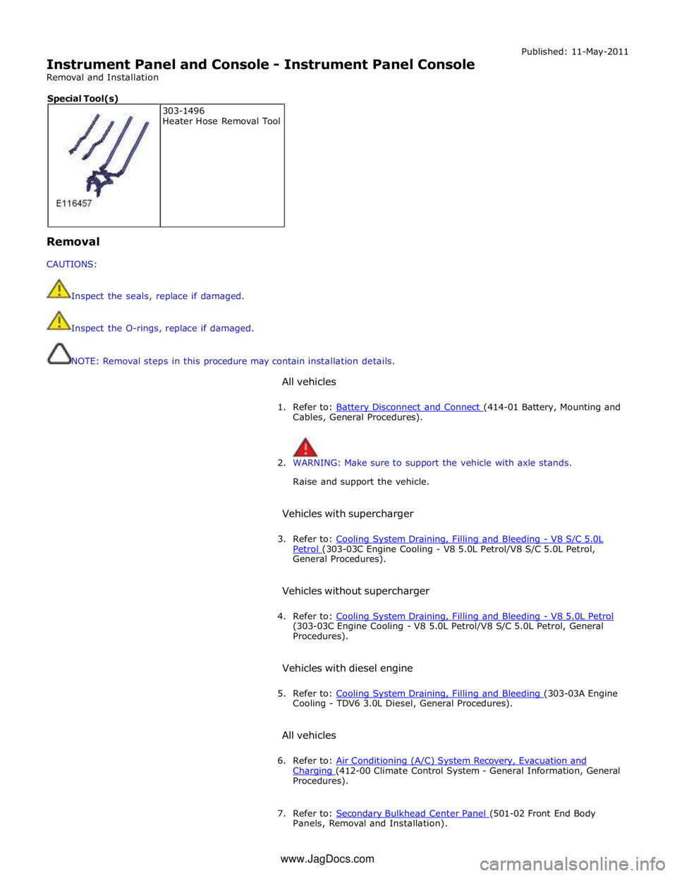
7. Refer to: Secondary Bulkhead Center Panel (501-02 Front End Body Panels, Removal and Installation). 303-1496
Heater Hose Removal Tool Special Tool(s)
www.JagDocs.com
Page 2537 of 3039

7 Windshield washer pump 8 Wiper/Washer switch - RH (right-hand) steering column multifunction switch 9 Instrument cluster 10 CJB (central junction box) 11 BJB (battery junction box)
WINDSHIELD WIPERS System Operation
Operation of the wipers and washers is controlled by the CJB in response to driver inputs from the wiper control switch and signals from the rain/light sensor. The instrument cluster monitors the condition of the wiper/washer control switch and
transmits driver requests to the CJB over the medium speed CAN bus.
The wiper control switch is connected via hardwired connections to the instrument cluster. The instrument cluster outputs on 4
wires a reference voltage to the wash/wipe switch, the auto wiper switch, the wiper switch and the flick wipe switch. All the
switches are connected to the instrument cluster on a common ground. Each switch function is connected to ground via a
resistor or series of resistors and the instrument cluster monitors the ground signal and determines which function has been
selected. The instrument cluster then outputs the appropriate message on the medium speed CAN bus to the CJB which responds to the requested wiper function. The CJB then activates the appropriate function either directly or via relays in the EJB for the wipers and headlamp powerwashers. Speed Dependent Mode
When the wipers are operating, a vehicle speed signal received by the CJB on the high speed CAN bus is used to operate a speed dependent mode. If the wipers are in fast wipe and the vehicle speed decreases to below 2 km/h (1.2 mph), the wipers
will reduce to the normal wipe speed. When the vehicle speed increases to above 8 km/h (5 mph) the fast wiper speed
selection is restored. If slow speed is selected and the vehicle speed drops below 2km/h (1.2 mph), the wipers will operate in
the intermittent mode. When the vehicle speed increases to above 8 km/h (5 mph) the slow wiper speed selection is restored
– this feature is configurable by the dealer using the approved Jaguar diagnostic system.
Wiper Motor
The wiper motor is controlled by the CJB. The CJB is connected to a wiper motor normal/fast relay in the EJB on 2 wires. The CJB is also connected to a wiper run/park relay, also located in the EJB.
Driver requests are received by the CJB which energizes the wiper motor normal/fast relay in the appropriate mode (normal or fast wipe) and also energizes the run/park relay in the run mode by providing a ground for the relay coils. When wiper
operation is deselected by the driver, the CJB monitors a park switch which is integral with the wiper motor. On receipt of a signal from the park switch, the CJB de-energises the run/park relay, removing the power supply through the normal/fast relay, stopping the wipers in the park position on the windshield.
The wiper motor is a DC (direct current) motor which drives a gear wheel via a worm drive attached to the motor spindle. The
motor has 3 sets of brushes with one brush connected to ground. When the normal/fast relay is energized in the normal
position, a power feed is supplied to the brush directly opposite the ground brush and operates the motor at slow speed.
When the relay is energized in the fast position, a power feed is connected to the second motor brush, which is offset from the
ground brush and operates the motor at the fast speed. With power supplied through the offset brush, the current flows
through fewer motor coil windings. This results in a lower resistance to current flow to the ground brush and produces a higher
motor rotational speed.
WINDSHIELD WASHERS
The windshield washers are controlled by the CJB. A driver request for washer operation, via the wiper control switch, is passed to the instrument cluster on the LIN bus. The instrument cluster passes the message to the CJB on the medium speed CAN bus.
The CJB energizes the windshield washer pump during the up stroke of the first 2 wash/wipe cycles. This ensures that wiper fluid is pushed to the sides of the windshield and eliminates the trail of fluid which can occur if the fluid is pushed to the
bottom of the windshield. The wipers will continue for 3 more cycles, followed after a delay of 4 seconds, by a single dry wipe.
NOTE: The dry wipe feature is configurable using an approved Jaguar diagnostic system.
The operation of the washer pump on the wiper up stroke only is configurable using an approved Jaguar diagnostic system.
The washer button can be pressed and held and the wipers will operate continuously for up to 10 seconds. After this period
when the button is released, the wipers will continue for 3 more cycles, followed after a delay, by a single dry wipe. After this
period washing will be inhibited, the wipers will continue for 3 more cycles, followed after a delay, by a single dry wipe.
Reactivating the switch will recommence the wash/wipe cycle.
RESERVOIR LEVEL SWITCH
The level switch is connected directly to the CJB. The switch is operated by a float which closes contacts within the switch when the fluid level falls to below the switch level. When the contacts are closed a ground path is completed from the CJB through the switch. This is sensed by the CJB which issues a message to the instrument cluster which displays a low fluid level warning.