2010 JAGUAR XFR warning
[x] Cancel search: warningPage 2679 of 3039
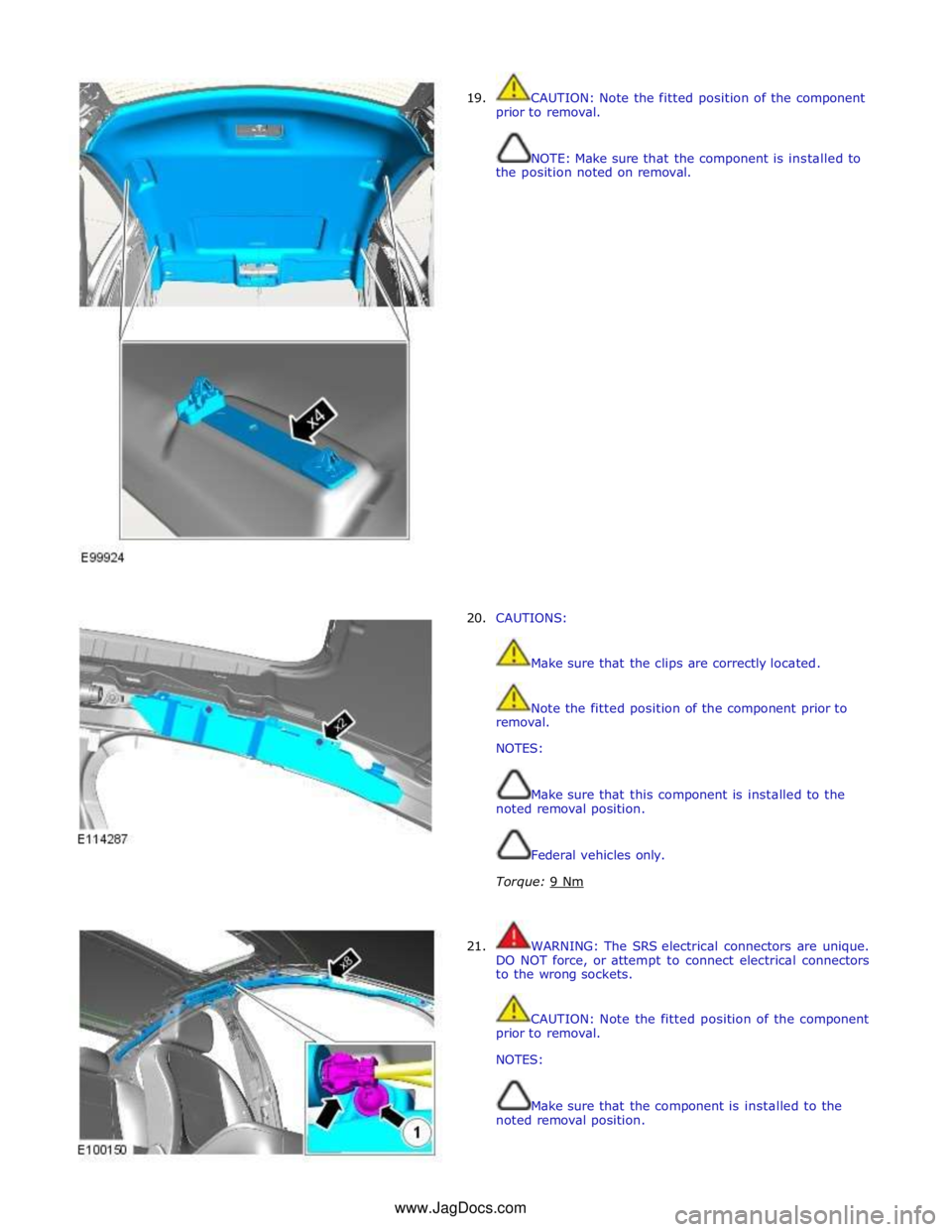
19.
20.
CAUTION: Note the fitted position of the component
prior to removal.
NOTE: Make sure that the component is installed to
the position noted on removal.
CAUTIONS:
Make sure that the clips are correctly located.
Note the fitted position of the component prior to
removal.
NOTES:
Make sure that this component is installed to the
noted removal position.
Federal vehicles only.
Torque: 9 Nm
21. WARNING: The SRS electrical connectors are unique.
DO NOT force, or attempt to connect electrical connectors
to the wrong sockets.
CAUTION: Note the fitted position of the component
prior to removal.
NOTES:
Make sure that the component is installed to the
noted removal position. www.JagDocs.com
Page 2682 of 3039
Published: 11-May-2011
Pedestrian Protection System - Pedestrian Protection System - Overview
Description and Operation
OVERVIEW
WARNING: All pyrotechnic devices are dangerous. Before performing any procedures on any pyrotechnic device, read all
information contained within the Standard Workshop Practices section of this manual.
Refer to: Standard Workshop Practices (100-00 General Information, Description and Operation).
The pedestrian protection system is designed to mitigate injuries in a pedestrian collision with the vehicle. It does this by
utilizing a pair of pyrotechnic actuators to lift the hood away from the engine, creating a cushioned impact between the
pedestrian and the vehicle.
The pedestrian protection system also includes passive protection integrated into the bumper system and bonnet structure.
WARNING: Do not fit any non-Jaguar approved accessories to the vehicle.
NOTE: The pedestrian protection system operates independently from the SRS (supplemental restraint system).
Page 2684 of 3039
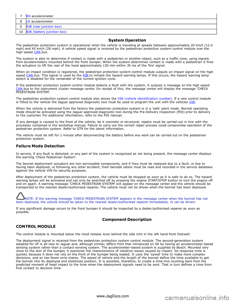
7 RH accelerometer 8 LH accelerometer 9 RJB (rear junction box) 10 BJB (battery junction box)
System Operation
The pedestrian protection system is operational when the vehicle is traveling at speeds between approximately 20 km/h (12.4
mph) and 45 km/h (28 mph). A vehicle speed signal is received by the pedestrian protection system control module over the
high speed CAN bus.
The system is able to determine if contact is made with a pedestrian or another object, such as a traffic cone, using signals
from accelerometers mounted behind the front bumper. When the system determines contact is made with a pedestrian it fires
the actuators to lift the rear of the hood approximately 130 mm within 35 ms of the 'fire' signal.
When an impact condition is registered, the pedestrian protection system control module outputs an impact signal on the high
speed CAN bus. This signal is used by the RJB to initiate the hazard warning lamps. If this occurs, the hazard warning lamp switch is disabled for the remainder of the current ignition cycle.
If the pedestrian protection system control module detects a fault with the system, it outputs a message on the high speed
CAN bus to the instrument cluster message center. On receipt of this, the message center will display the message 'CHECK PEDESTRIAN SYSTEM'.
The pedestrian protection system control module also stores the VIN (vehicle identification number). If a new control module
is fitted to the vehicle the Jaguar approved diagnostic tool must be used to program the unit with the vehicles VIN.
When the vehicle is delivered from the factory the pedestrian protection system is in a 'safe' plant mode. Normal operating
mode should be activated using the Jaguar approved diagnostic tool during the Pre-Delivery Inspection (PDI) prior to delivery
to the customer. For additional information, refer to the PDI manual.
If any damage is caused to the front of the vehicle, be it cosmetic or structural, repairs must be carried out in line with the
processes contained in the workshop manual. Failure to carry out the correct repair process could compromise operation of the
pedestrian protection system. Refer to GTR for the latest information.
The vehicle must be left for 1 minute after disconnecting the battery before any work can be carried out on the pedestrian
protection system.
Failure Mode Detection
In service, if any fault is detected, or any part of the system is recognized as not being present, the message center displays
the warning 'Check Pedestrian System'.
The bonnet deployment actuators are non-serviceable components, and if they must be replaced due to a fault, or due to
having been deployed, or following any other accident, their barcode labels must be read and recorded in the service database
against the vehicle VIN for security purposes.
After deployment of the pedestrian protection system, the vehicle must be stopped as soon as it is safe to do so. The hazard
warning lamps will be activated and can only be switched off by pressing the engine START/STOP button to turn the engine off
and on again. A warning message 'CHECK PEDESTRIAN SYSTEM' will appear on the message center and the vehicle should be
transported to the nearest dealer/authorised repairer. The vehicle must not be driven when the bonnet has been deployed.
NOTE: If the warning message 'CHECK PEDESTRIAN SYSTEM' appears in the message center when the bonnet has not
been deployed, the vehicle should be taken to the nearest dealer/authorised repairer immediately. It can be driven.
If any significant damage occurs to the front bumper it should be inspected by a dealer/authorised repairer as soon as
possible.
CONTROL MODULE Component Description
The control module is mounted below the hood release lever behind the side trim in the left hand front footwell.
The deployment signal is received from the pedestrian protection system control module. The second-generation system
adopted for XF is all-new to Jaguar and, although similar, differs from that introduced on XK by having an accelerometer-based
sensing system rather than a contact-sensing system. The accelerometer-based system is supplied by Bosch. Mounted very
close to the skin of the bumper, it examines the characteristics of vibration waves caused by impact. Its response time is
quicker, because it does not rely on the front of the bumper being loaded. It uses the 'saved' time to make more complex
decisions, and so has fewer error states. The speed of vehicle and the length of the bonnet define the time available to get
the bonnet into its deployed and stabilized position. It is possible, therefore, to create a time-line counting back from the
predicted moment of head impact to the time when the deployment signals need to be sent. That in turn defines a time from
first contact to decision time.
www.JagDocs.com
Page 2687 of 3039
Pedestrian Protection System - Pedestrian Protection System
Diagnosis and Testing
Principles of Operation Published: 09-Dec-2013
For a detailed description of the Pedestrian Protection System, refer to the relevant Description and Operation section in the
workshop manual.
REFER to: Pedestrian Protection System (501-20C Pedestrian Protection System, Description and Operation) / Pedestrian Protection System (501-20C Pedestrian Protection System, Description and Operation) / Pedestrian Protection System (501-20C Pedestrian Protection System, Description and Operation).
Inspection and Verification
WARNINGS:
TO AVOID ACCIDENTAL DEPLOYMENT AND POSSIBLE PERSONAL INJURY, THE BACKUP POWER SUPPLY MUST BE DEPLETED
BEFORE REPAIRING OR REPLACING ANY PEDESTRIAN PROTECTION SYSTEM COMPONENTS. TO DEPLETE THE BACKUP POWER
SUPPLY ENERGY, DISCONNECT THE BATTERY GROUND CABLE AND WAIT TWO MINUTES. FAILURE TO FOLLOW THIS
INSTRUCTION MAY RESULT IN PERSONAL INJURY.
Do not use a multimeter to probe the pedestrian protection system actuators. It is possible for the power from the
multimeter battery to trigger the activation of the actuator. Failure to follow this instruction may result in personal injury.
CAUTION: Diagnosis by substitution from a donor vehicle is NOT acceptable. Substitution of control modules does not
guarantee confirmation of a fault, and may also cause additional faults in the vehicle being tested and/or the donor vehicle.
NOTES:
If the control module or a component is suspect and the vehicle remains under manufacturer warranty, refer to the
Warranty Policy and Procedures manual (section B1.2), or determine if any prior approval programme is in operation, prior to
the installation of a new module/component.
When performing voltage or resistance tests, always use a digital multimeter accurate to three decimal places, and with
an up-to-date calibration certificate. When testing resistance always take the resistance of the digital multimeter leads into
account.
Check and rectify basic faults before beginning diagnostic routines involving pinpoint tests.
It is advisable not to use a cellular phone or to have a cellular phone in close proximity when working on the pedestrian
protection system or components
Given the legal implications of a restraints system failure, harness repairs to pedestrian protection system circuits are
not acceptable. Where the text refers to "REPAIR the circuit", this will normally mean the replacement of a harness.
After 5 hood deployment events, a new Pedestrian Protection System Control Module (PPSCM) and wiring harness must be
installed.
1. Verify the customer concern
2. Visually inspect for obvious signs of damage and system integrity
Visual Inspection
Mechanical Electrical
Hood
Hood hinge
Hood deployment controls
Fuses
Wiring harnesses and connectors
Pedestrian Protection System Control Module (PPSCM)
Impact sensors
Hood deployment controls
3. If an obvious cause for an observed or reported concern is found, correct the cause (if possible) before proceeding to
the next step
4. If the cause is not visually evident, verify the symptom and refer to the Symptom Chart, alternatively check for
Page 2688 of 3039
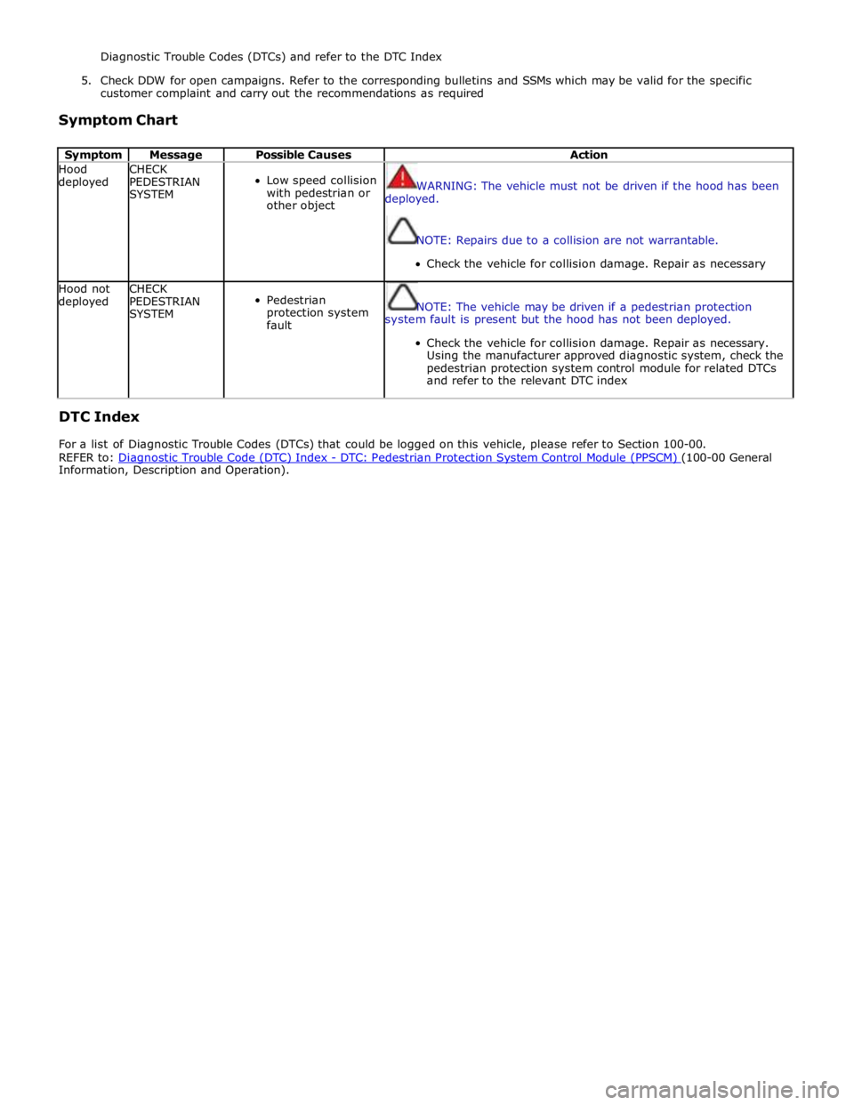
Diagnostic Trouble Codes (DTCs) and refer to the DTC Index
5. Check DDW for open campaigns. Refer to the corresponding bulletins and SSMs which may be valid for the specific
customer complaint and carry out the recommendations as required
Symptom Chart
Symptom Message Possible Causes Action Hood
deployed CHECK
PEDESTRIAN
SYSTEM
Low speed collision
with pedestrian or
other object
WARNING: The vehicle must not be driven if the hood has been
deployed.
NOTE: Repairs due to a collision are not warrantable.
Check the vehicle for collision damage. Repair as necessary Hood not
deployed CHECK
PEDESTRIAN
SYSTEM
Pedestrian
protection system
fault
NOTE: The vehicle may be driven if a pedestrian protection
system fault is present but the hood has not been deployed.
Check the vehicle for collision damage. Repair as necessary.
Using the manufacturer approved diagnostic system, check the
pedestrian protection system control module for related DTCs
and refer to the relevant DTC index
DTC Index
For a list of Diagnostic Trouble Codes (DTCs) that could be logged on this vehicle, please refer to Section 100-00.
REFER to: Diagnostic Trouble Code (DTC) Index - DTC: Pedestrian Protection System Control Module (PPSCM) (100-00 General Information, Description and Operation).
Page 2709 of 3039
NOTE: It is preferable to repair body parts rather than to renew them, as this keeps the complete body-shell
intact.
Which body parts need to be renewed?
Which body parts can be repaired?
Obtaining spare parts
The availability of spare parts often determines how easily the body repairs can be carried out. The following procedure is
recommended:
Obtain all the data for the vehicle, including type, vehicle identification number, trim code, engine identification letters,
initial registration etc.
Establish all of the metal parts that need to be renewed.
Establish all of the attached parts that need to be renewed, including small parts like rivets, clips etc.
Straightening repairs
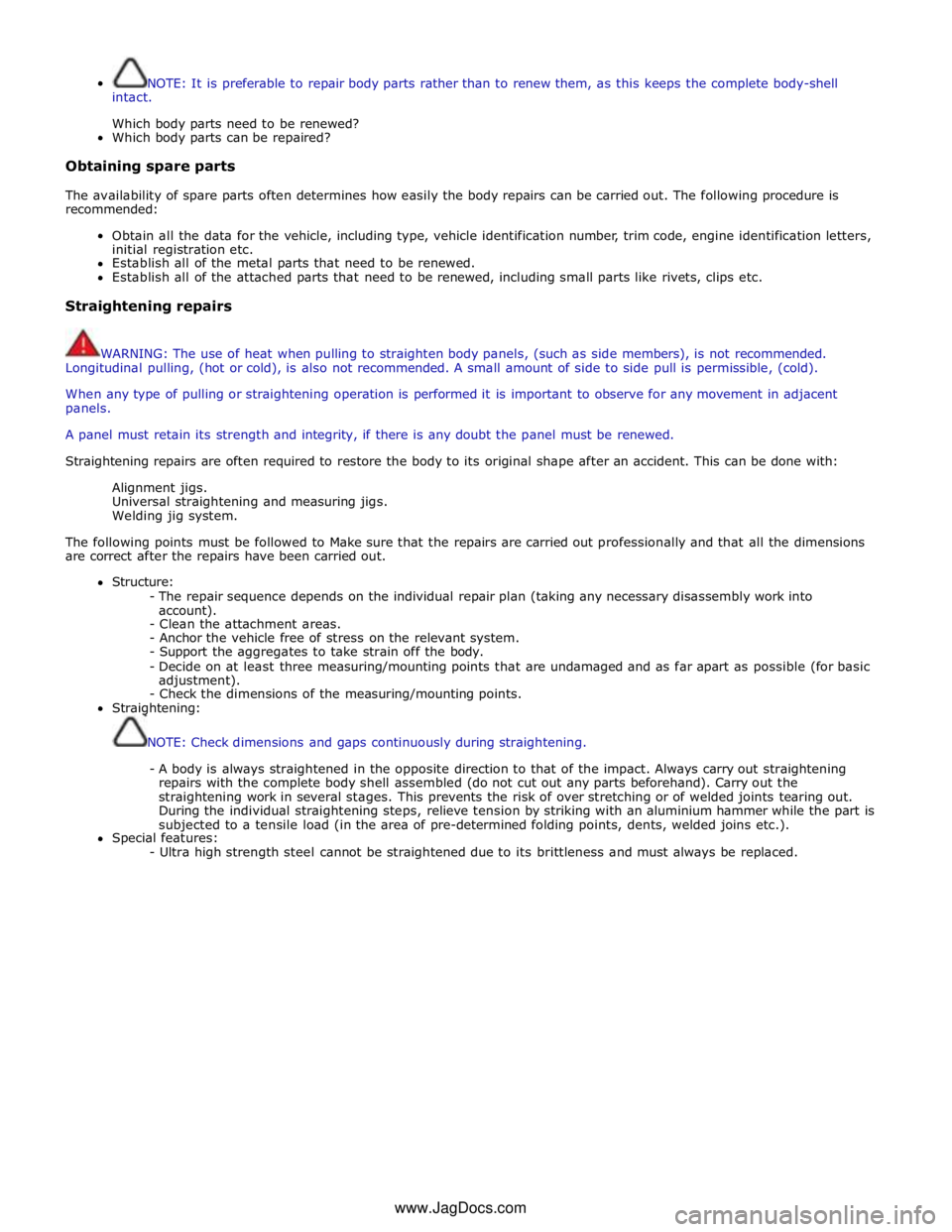
WARNING: The use of heat when pulling to straighten body panels, (such as side members), is not recommended.
Longitudinal pulling, (hot or cold), is also not recommended. A small amount of side to side pull is permissible, (cold).
When any type of pulling or straightening operation is performed it is important to observe for any movement in adjacent
panels.
A panel must retain its strength and integrity, if there is any doubt the panel must be renewed.
Straightening repairs are often required to restore the body to its original shape after an accident. This can be done with:
Alignment jigs.
Universal straightening and measuring jigs.
Welding jig system.
The following points must be followed to Make sure that the repairs are carried out professionally and that all the dimensions
are correct after the repairs have been carried out.
Structure:
- The repair sequence depends on the individual repair plan (taking any necessary disassembly work into
account).
- Clean the attachment areas.
- Anchor the vehicle free of stress on the relevant system.
- Support the aggregates to take strain off the body.
- Decide on at least three measuring/mounting points that are undamaged and as far apart as possible (for basic
adjustment).
- Check the dimensions of the measuring/mounting points.
Straightening:
NOTE: Check dimensions and gaps continuously during straightening.
- A body is always straightened in the opposite direction to that of the impact. Always carry out straightening
repairs with the complete body shell assembled (do not cut out any parts beforehand). Carry out the
straightening work in several stages. This prevents the risk of over stretching or of welded joints tearing out.
During the individual straightening steps, relieve tension by striking with an aluminium hammer while the part is
subjected to a tensile load (in the area of pre-determined folding points, dents, welded joins etc.).
Special features:
- Ultra high strength steel cannot be straightened due to its brittleness and must always be replaced. www.JagDocs.com
Page 2820 of 3039
Front End Sheet Metal Repairs - Hood Latch Panel
Removal and Installation
Removal Published: 11-May-2011
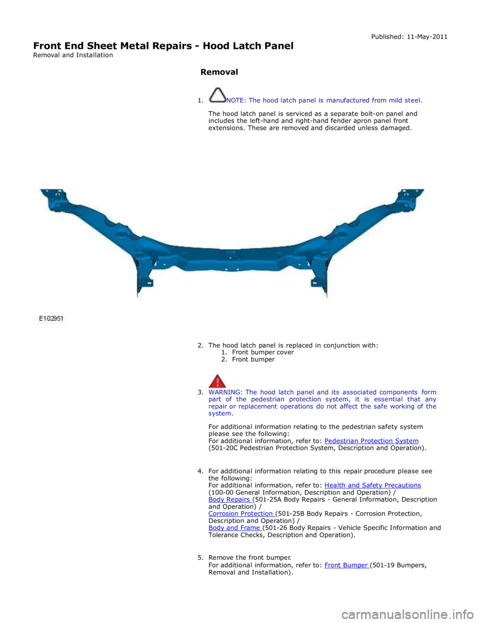
1. NOTE: The hood latch panel is manufactured from mild steel.
The hood latch panel is serviced as a separate bolt-on panel and
includes the left-hand and right-hand fender apron panel front
extensions. These are removed and discarded unless damaged.
2. The hood latch panel is replaced in conjunction with:
1. Front bumper cover
2. Front bumper
3. WARNING: The hood latch panel and its associated components form
part of the pedestrian protection system, it is essential that any
repair or replacement operations do not affect the safe working of the
system.
For additional information relating to the pedestrian safety system
please see the following:
For additional information, refer to: Pedestrian Protection System (501-20C Pedestrian Protection System, Description and Operation).
4. For additional information relating to this repair procedure please see
the following:
For additional information, refer to: Health and Safety Precautions (100-00 General Information, Description and Operation) /
Body Repairs (501-25A Body Repairs - General Information, Description and Operation) /
Corrosion Protection (501-25B Body Repairs - Corrosion Protection, Description and Operation) /
Body and Frame (501-26 Body Repairs - Vehicle Specific Information and Tolerance Checks, Description and Operation).
5. Remove the front bumper.
For additional information, refer to: Front Bumper (501-19 Bumpers, Removal and Installation).
Page 3014 of 3039
Published: 31-Jul-2013
Uni-Body, Subframe and Mounting System - Front Subframe V8 5.0L Petrol/V8 S/C 5.0L Petrol
Removal and Installation
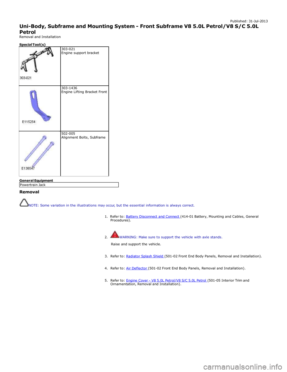
Special Tool(s)
303-021
Engine support bracket
303-1436
Engine Lifting Bracket Front
502-005
Alignment Bolts, Subframe General Equipment
Removal
NOTE: Some variation in the illustrations may occur, but the essential information is always correct.
1. Refer to: Battery Disconnect and Connect (414-01 Battery, Mounting and Cables, General Procedures).
2. WARNING: Make sure to support the vehicle with axle stands.
Raise and support the vehicle.
3. Refer to: Radiator Splash Shield (501-02 Front End Body Panels, Removal and Installation). 4. Refer to: Air Deflector (501-02 Front End Body Panels, Removal and Installation). 5. Refer to: Engine Cover - V8 5.0L Petrol/V8 S/C 5.0L Petrol (501-05 Interior Trim and Ornamentation, Removal and Installation). Powertrain Jack