2010 JAGUAR XFR warning
[x] Cancel search: warningPage 2571 of 3039
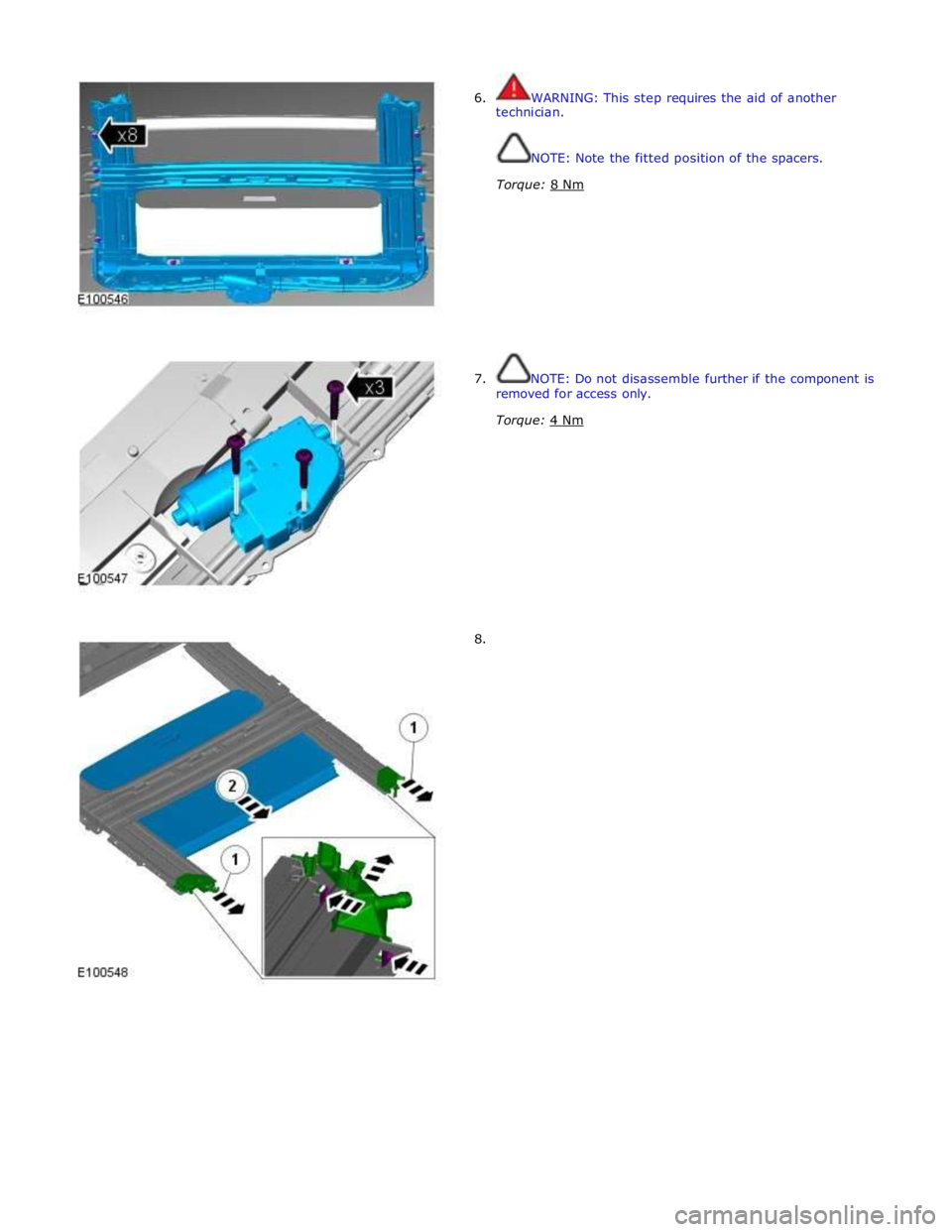
6. WARNING: This step requires the aid of another
technician.
NOTE: Note the fitted position of the spacers.
Torque: 8 Nm
7. NOTE: Do not disassemble further if the component is
removed for access only.
Torque: 4 Nm
8.
Page 2580 of 3039
Bumpers - Front Bumper
Removal and Installation Published: 11-May-2011
Removal
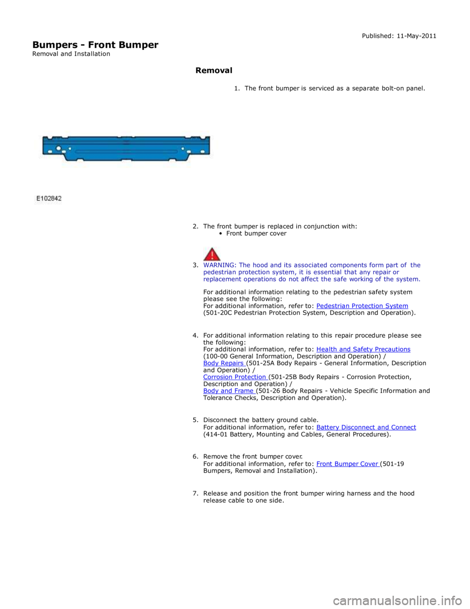
1. The front bumper is serviced as a separate bolt-on panel.
2. The front bumper is replaced in conjunction with:
Front bumper cover
3. WARNING: The hood and its associated components form part of the
pedestrian protection system, it is essential that any repair or
replacement operations do not affect the safe working of the system.
For additional information relating to the pedestrian safety system
please see the following:
For additional information, refer to: Pedestrian Protection System (501-20C Pedestrian Protection System, Description and Operation).
4. For additional information relating to this repair procedure please see
the following:
For additional information, refer to: Health and Safety Precautions (100-00 General Information, Description and Operation) /
Body Repairs (501-25A Body Repairs - General Information, Description and Operation) /
Corrosion Protection (501-25B Body Repairs - Corrosion Protection, Description and Operation) /
Body and Frame (501-26 Body Repairs - Vehicle Specific Information and Tolerance Checks, Description and Operation).
5. Disconnect the battery ground cable.
For additional information, refer to: Battery Disconnect and Connect (414-01 Battery, Mounting and Cables, General Procedures).
6. Remove the front bumper cover.
For additional information, refer to: Front Bumper Cover (501-19 Bumpers, Removal and Installation).
7. Release and position the front bumper wiring harness and the hood
release cable to one side.
Page 2582 of 3039
Bumpers - Front Bumper Cover
Removal and Installation
Removal
NOTE: Removal steps in this procedure may contain installation details. Published: 11-May-2011
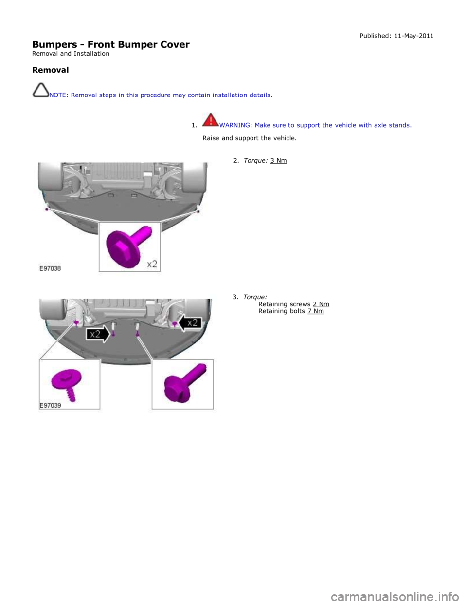
1. WARNING: Make sure to support the vehicle with axle stands.
Raise and support the vehicle.
2. Torque: 3 Nm 3. Torque:
Retaining screws 2 Nm Retaining bolts 7 Nm
Page 2593 of 3039

Safety Belt System - Safety Belt System - Overview
Description and Operation
Authoring Template
OVERVIEW Published: 11-May-2011
A three point safety belt is fitted to all seating positions. Each safety belt retractor incorporates an emergency locking feature.
The emergency locking retractor incorporates 2 mechanical inertia devices. One inertia device activates if the safety belt is
subjected to a sharp pull. The second inertia device activates if the vehicle is subject to a sudden deceleration or is on a
severe incline.
North American Specification (NAS) safety belt retractors also include an automatic locking feature. The Automatic Locking
Retractor (ALR) is fitted to all passenger seating positions and allows the safety belt to be tensioned to aid the safe fitment
of child or booster seats. For additional information, refer to the Owners Handbook.
NAS vehicles are also fitted with a belt tension sensor on the front passenger seat. The belt tension sensor is incorporated
into the seat belt lower anchorage and is attached to the seat frame by an M10 Torx head bolt. The belt tension sensor forms
part of the SRS (supplemental restraint system) occupancy detection and classification feature.
The center rear safety belt features a mini-buckle lower anchorage. The mini-buckle is disengaged by inserting a suitable tool
into the small aperture on the front face of the housing.
To aid the fitment of child seats, 3 tethers are located on the rear parcel shelf. Each tether is attached to the parcel shelf with
an M10 Torx head bolt.
A safety belt warning indicator is located in the instrument cluster to remind front seat passengers to fasten their safety belts.
The warning indicator will illuminate if the safety belt of an occupied front seat is not fastened.
Refer to: Instrument Cluster (413-01, Description and Operation).
Page 2595 of 3039
Safety Belt System - Safety Belt System
Diagnosis and Testing
Principle of Operation Published: 13-Jun-2013
For a detailed description of the seatbelt system and operation, refer to the relevant description and operation section of the
workshop manual REFER to: (501-20A Safety Belt System)
Safety Belt System (Description and Operation), Safety Belt System (Description and Operation), Safety Belt System (Description and Operation).
Safety Information
WARNINGS:
To avoid accidental deployment the back-up power supply must be depleted before beginning any work on the SRS system
or its components. Failure to follow this instruction may result in personal injury
Do not use a multimeter to probe an SRS module. It is possible for the power from the multimeter battery to trigger the
activation of the module. Failure to follow this instruction may result in personal injury
NOTE: Do not to use a cellular phone or to have a cellular phone in close proximity when working on the SRS system or
components
Power supply depletion
Before beginning any work on the SRS system or related components:
1. Remove the ignition key
2. Disconnect the battery leads, ground first
3. Wait 2 minutes for the power circuit to discharge
There are comprehensive instructions on the correct procedures for SRS system repairs, refer to the relevant section of the
workshop manual
Inspection and Verification
CAUTION: Diagnosis by substitution from a donor vehicle is NOT acceptable. Substitution of control modules does not
guarantee confirmation of a fault and may also cause additional faults in the vehicle being checked and/or the donor vehicle
NOTE: Check and rectify basic faults before beginning diagnostic routines including pinpoint tests
1. Verify the customer concern by operating the seatbelt
2. Visually inspect for obvious signs of mechanical or electrical damage
Visual Inspection
Mechanical Electrical
Check for the installation of non-standard accessories which may affect or
obstruct the function of the seatbelt system
Frayed or damaged webbing
Missing or damaged button stop
Pretensioner(s) Buckles/Stalks
Fuses
Wiring harness fault
Correct engagement of electrical
connectors
Loose or corroded connections
Warning lamp bulb(s)
Impact sensor(s)
Buckle sensor(s)
Pretensioner(s)
Belt tension sensor(s)
Restraints control module
3. If an obvious cause for an observed or reported concern is found, correct the cause (if possible) before proceeding to
the next step
4. If the cause is not visually evident, carry out the test methods described below, alternatively check for diagnostic
trouble codes and refer to the relevant diagnostic trouble code index
Page 2611 of 3039
Published: 30-May-2012
Supplemental Restraint System - Air Bag and Safety Belt Pretensioner
Supplemental Restraint System (SRS) - Overview
Description and Operation
OVERVIEW
WARNING: All pyrotechnic devices are dangerous. Before performing any procedures on any pyrotechnic device, read all
information contained within the Standard Workshop Practices section of this manual.
Refer to: Standard Workshop Practices (100-00 General Information, Description and Operation).
The SRS (supplemental restraint system) provides additional protection for the vehicle occupants in certain impact conditions.
The system is controlled by the RCM (restraints control module), which is mounted beneath the floor console. The system
includes twin stage drivers and front passenger airbags.
The RCM receives inputs from various sensors around the vehicle and determines which, if any, airbags should be deployed.
The SRS features an occupant detection system. The occupant detection system comprises a mat fitted inside the front passenger seat. By monitoring the condition of the mat, the RCM can determine if the front passenger seat is occupied. It uses this information to determine which airbags to deploy in the event of an impact. This information is also used to illuminate the
safety belt instrument cluster warning lamp if the front passenger seat is occupied and the safety belt is not engaged.
North American Specification (NAS) vehicles also feature an occupant classification system. The occupant classification system
comprises a control module, pressure pad and safety belt tension sensor. The system can determine the size and weight of the
front seat passenger. This information is transmitted to the RCM over the high speed CAN (controller area network) bus. The RCM uses this information to help determine which airbags to deploy in the event of an impact.
Page 2615 of 3039
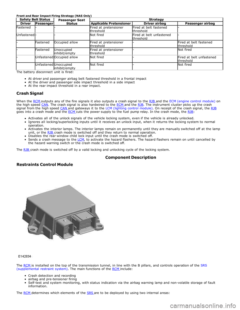
Driver Passenger Applicable Pretensioner Driver airbag Passenger airbag Fastened - -
Fired at pretensioner
threshold Fired at belt fastened
threshold - Unfastened - - Not fired
Fired at belt unfastened
threshold - - Fastened Occupied allow
Fired at pretensioner
threshold -
Fired at belt fastened
threshold - Fastened
Unoccupied inhibit/empty Fired at pretensioner
threshold - Not fired - Unfastened Occupied allow Not fired -
Fired at belt unfastened
threshold Unfastened
Unoccupied inhibit/empty Not fired - Not fired The battery disconnect unit is fired:
At driver and passenger airbag belt fastened threshold in a frontal impact
At the driver and passenger side impact threshold in a side impact
At the rear impact threshold in a rear impact.
Crash Signal
When the RCM outputs any of the fire signals it also outputs a crash signal to the RJB and the ECM (engine control module) on the high speed CAN. The crash signal is also hardwired to the ECM and the RJB. The instrument cluster picks up the crash signal from the high speed CAN and gateways it to the LCM (lighting control module). On receipt of the crash signal, the RJB goes into a crash mode and the ECM cuts the power supply to the fuel pump relay. In the crash mode, the RJB: Activates all of the unlock signals of the vehicle locking system, even if the vehicle is already unlocked.
Ignores all locking/superlocking inputs until it receives an unlock input, when it returns the locking system to normal
operation.
Activates the interior lamps. The interior lamps remain on permanently until they are manually switched off at the lamp
unit, or the RJB crash mode is switched off and they return to normal operation. Disables the rear window child lock input until the crash mode is switched off.
Sends a crash message to the LCM, to activate the hazard flashers. The hazard flashers remain on until cancelled by the hazard warning switch or the crash mode is switched off.
The RJB crash mode is switched off by a valid locking and unlocking cycle of the locking system.
Restraints Control Module Component Description
The RCM is installed on the top of the transmission tunnel, in line with the B pillars, and controls operation of the SRS (supplemental restraint system). The main functions of the RCM include:
Crash detection and recording
airbag and pre-tensioner firing
Self-test and system monitoring, with status indication via the airbag warning lamp and non-volatile storage of fault
information.
The RCM determines which elements of the SRS are to be deployed by using two internal areas:
Page 2616 of 3039
and the safety belt buckle sensor. Based on this data, the RCM decides which level of airbag module deployment is required and forwards the information to the second area, the deployment handler.
The deployment handler evaluates the status of the seat track position sensor and safety belt buckle sensors before a decision
is made about which restraints should finally be deployed.
Data from the side crash sensors is used by the RCM in conjunction with acceleration data from the RCM internal accelerometer to make a deployment decision. The RCM processes the acceleration data and subject to an impact being of high enough severity, decides whether the side airbag module should be deployed.
On board testing of the airbag modules, front safety belt pretensioner firing circuits, warning indicator circuits and module
status (the crash and side impact sensors perform basic self-tests) is performed by the RCM together with the storing of fault codes.
The RCM drives the SRS indicator on the instrument pack via a CAN signal. If the warning lamp fails, a fault code is recorded and a warning tone is sounded in place of the lamp if a further fault occurs. It also provides a temporary back-up power supply
to operate the airbag modules in the event that in crash conditions, the battery supply is lost. In the event of a crash, it
records certain data which can be accessed via the diagnostic connector.
A safing sensor in the RCM provides confirmation of an impact to verify if airbag and pretensioner activation is necessary. A roll-over sensor monitors the lateral attitude of the vehicle. Various firing strategies are employed by the RCM to ensure that during an accident only the appropriate airbags and pretensioners are fired. The firing strategy used also depends on the
inputs from the safety belt switches and the occupant monitoring system.
An energy reserve in the RCM ensures there is always a minimum of 150 milliseconds of stored energy available if the power supply from the ignition switch is disrupted during a crash. The stored energy is sufficient to produce firing signals for the
driver airbag, the passenger airbag and the safety belt pretensioners.
When the ignition is switched on, the RCM performs a self-test and then performs cyclical monitoring of the system. If a fault is detected the RCM stores a related fault code and illuminates the airbag warning indicator. The faults can be retrieved by the recommended Jaguar diagnostic tool over the CAN bus. If a fault that could cause a false fire signal is detected, the RCM disables the respective firing circuit, and keeps it disabled during a crash event.
Clock Spring
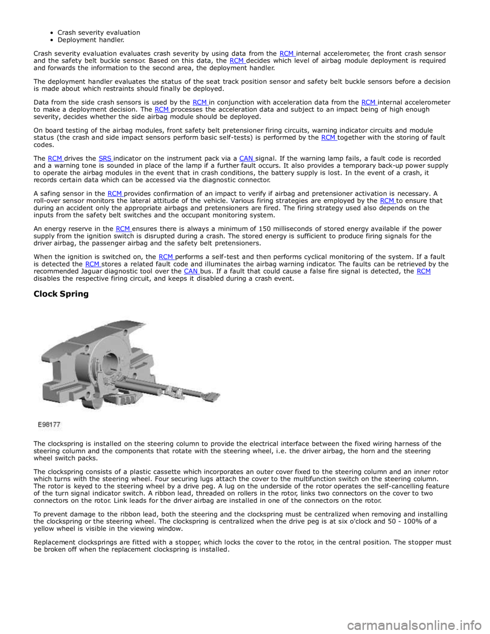
The clockspring is installed on the steering column to provide the electrical interface between the fixed wiring harness of the
steering column and the components that rotate with the steering wheel, i.e. the driver airbag, the horn and the steering
wheel switch packs.
The clockspring consists of a plastic cassette which incorporates an outer cover fixed to the steering column and an inner rotor
which turns with the steering wheel. Four securing lugs attach the cover to the multifunction switch on the steering column.
The rotor is keyed to the steering wheel by a drive peg. A lug on the underside of the rotor operates the self-cancelling feature
of the turn signal indicator switch. A ribbon lead, threaded on rollers in the rotor, links two connectors on the cover to two
connectors on the rotor. Link leads for the driver airbag are installed in one of the connectors on the rotor.
To prevent damage to the ribbon lead, both the steering and the clockspring must be centralized when removing and installing
the clockspring or the steering wheel. The clockspring is centralized when the drive peg is at six o'clock and 50 - 100% of a
yellow wheel is visible in the viewing window.
Replacement clocksprings are fitted with a stopper, which locks the cover to the rotor, in the central position. The stopper must
be broken off when the replacement clockspring is installed.