2010 JAGUAR XFR warning
[x] Cancel search: warningPage 2095 of 3039

DTC Description Possible Causes Action Write target SID
synchronisation error
following re-programming
Noise/EMC related error B100A63
Fuel Pump
Authorisation
RJB fault
Low speed CAN fault
Instrument cluster fault
Low battery voltage <9V Check power and ground supplies to RJB and instrument cluster.
Check CAN communications between RJB and instrument cluster.
Check battery is in fully charged and serviceable condition, refer
to the battery care manual B102612
Steering Column
Lock
Steering column lock
ground circuit - short to
power Refer to the electrical circuit diagrams and check steering column
lock ground circuit for short to power B108783 LIN Bus "A"
The checksum of the
received LIN frame is
incorrect Check the battery monitoring system and rear parking aid system
for DTCs and refer to relevant DTC Index B108786 LIN Bus "A"
The header of the LIN
message received is
incorrect Carry out any pinpoint test associated with this DTC using the
manufacturer approved diagnostic system. Check the battery
monitoring system and rear parking aid system for DTCs and
refer to relevant DTC Index B108788 LIN Bus "A"
Battery monitoring
system LIN circuit - short
to ground, power Carry out any pinpoint test associated with this DTC using the
manufacturer approved diagnostic system. Refer to the electrical
circuit diagrams and check battery monitoring system LIN circuit
for short to ground, power B108A23 Start Button
Start/Stop switch digital
input signal circuit -
stuck low Carry out any pinpoint test associated with this DTC using the
manufacturer approved diagnostic system. Refer to the electrical
circuit diagrams and check Start/Stop switch digital input signal
circuit for short to ground B10A111 Trailer Tow
Detection
Trailer tow detection
digital input circuit -
short to ground Carry out any pinpoint test associated with this DTC using the
manufacturer approved diagnostic system. Refer to the electrical
circuit diagrams and check trailer tow detection digital input
circuit for short to ground B10AF12 Blower Fan Relay
High Side output not
driven - Diagnosis
feedback indicates output
is short to power Refer to the electrical circuit diagrams and check blower motor
supply circuit for short to power B10AF14 Blower Fan Relay
High Side output not
driven - Diagnosis
feedback indicates output
is short to ground, open
circuit Refer to the electrical circuit diagrams and check blower motor
supply circuit for short to ground, open circuit B10AF93 Blower Fan Relay
High Side output not
driven - Diagnosis
feedback indicates output
is at open load or short
to power Carry out any pinpoint test associated with this DTC using the
manufacturer approved diagnostic system. Refer to the electrical
circuit diagrams and check blower motor supply circuit for short
to power, open circuit B10DD11 Airbag Deployed
Airbag deployed digital
input signal circuit - short
to ground Carry out any pinpoint test associated with this DTC using the
manufacturer approved diagnostic system. Refer to the electrical
circuit diagrams and check airbag deployed digital input signal
circuit for short to ground B10DD15 Airbag Deployed
Airbag deployed digital
input signal circuit - short
to power, open circuit Carry out any pinpoint test associated with this DTC using the
manufacturer approved diagnostic system. Refer to the electrical
circuit diagrams and check airbag deployed digital input signal
circuit for short to power, open circuit B10DD38 Airbag Deployed
Signal frequency incorrect Check the RCM for related DTCs and refer to the relevant DTC
Index B10DE11
Low Fuel Warning
Switch
Diesel run-dry switch
analogue input circuit -
short to ground Carry out any pinpoint test associated with this DTC using the
manufacturer approved diagnostic system. Refer to the electrical
circuit diagrams and check diesel run-dry switch analogue input
circuit for short to ground www.JagDocs.com
Page 2096 of 3039

DTC Description Possible Causes Action B10DE15
Low Fuel Warning
Switch
Diesel run-dry switch
analogue input circuit -
short to power, open
circuit Carry out any pinpoint test associated with this DTC using the
manufacturer approved diagnostic system. Refer to the electrical
circuit diagrams and check diesel run-dry switch analogue input
circuit for short to power, open circuit B111211 Park Aid Ignition
Parking aid ignition
supply circuit - short to
ground Carry out any pinpoint test associated with this DTC using the
manufacturer approved diagnostic system. Refer to the electrical
circuit diagrams and check parking aid ignition supply circuit for
short to ground B111212 Park Aid Ignition
Parking aid ignition
supply circuit - short to
power Refer to the electrical circuit diagrams and check parking aid
ignition supply circuit for short to power B111511
High Mounted
Stop Lamp
Control
High mounted stop lamp
control circuit - short to
ground Carry out any pinpoint test associated with this DTC using the
manufacturer approved diagnostic system. Refer to the electrical
circuit diagrams and check high mounted stop lamp control circuit
for short to ground B111611 Left Tail Lamp
Left hand tail lamp
control circuit - short to
ground Carry out any pinpoint test associated with this DTC using the
manufacturer approved diagnostic system. Refer to the electrical
circuit diagrams and check left hand tail lamp control circuit for
short to ground B111711 Right Tail Lamp
Right hand tail lamp
control circuit - short to
ground Carry out any pinpoint test associated with this DTC using the
manufacturer approved diagnostic system. Refer to the electrical
circuit diagrams and check right hand tail lamp control circuit for
short to ground B111A11
Number Plate
Lamps
Right hand or left hand
number plate lamp
control circuits - short to
ground Carry out any pinpoint test associated with this DTC using the
manufacturer approved diagnostic system. Refer to the electrical
circuit diagrams and check right hand and left hand number plate
lamp control circuits for short to ground B111A12
Number Plate
Lamps
Right hand or left hand
number plate lamp
control circuits - short to
power Refer to the electrical circuit diagrams and check right hand and
left hand number plate lamp control circuits for short to power B111A13
Number Plate
Lamps
Right hand or left hand
number plate lamp
control circuits - open
circuit Refer to the electrical circuit diagrams and check right hand and
left hand number plate lamp control circuits for open circuit B111A-15
Number Plate
Lamps - circuit
short to battery
or open
Right or left side licence
plate lamp(s) inoperative
Right or left side licence
plate lamp control
circuits - short circuit to
power, open circuit, high
resistance
Refer to the electrical circuit diagrams and check right
side and left side licence plate lamp control circuits for
short circuit to power, open circuit, high resistance. Repair
wiring harness as required. Clear DTC and retest B111D12
Boot/Trunk Motor
Open
Luggage compartment lid
latch actuator control
circuit - short to power Carry out any pinpoint test associated with this DTC using the
manufacturer approved diagnostic system. Refer to the electrical
circuit diagrams and check luggage compartment lid latch
actuator control circuit for short to power B111D14
Boot/Trunk Motor
Open
Luggage compartment lid
latch actuator control
circuit - short to ground,
open circuit Carry out any pinpoint test associated with this DTC using the
manufacturer approved diagnostic system. Refer to the electrical
circuit diagrams and check luggage compartment lid latch
actuator control circuit for short to ground, open circuit B111E11 Boot/Trunk Lamps
Luggage compartment
lamp control circuit -
short to ground Carry out any pinpoint test associated with this DTC using the
manufacturer approved diagnostic system. Refer to the electrical
circuit diagrams and check luggage compartment lamp control
circuit for short to ground B111E12 Boot/Trunk Lamps
Luggage compartment
lamp control circuit -
short to power Refer to the electrical circuit diagrams and check luggage
compartment lamp control circuit for short to power
Page 2099 of 3039

DTC Description Possible Causes Action B124812
Right Rear Turn
Indicator
Right rear turn signal
lamp control circuit -
short to power Refer to the electrical circuit diagrams and check right rear turn
signal lamp control circuit for short to power B124813
Right Rear Turn
Indicator
Right rear turn signal
lamp control circuit -
open circuit Refer to the electrical circuit diagrams and check right rear turn
signal lamp control circuit for open circuit B1248-15
Right Rear Turn
Indicator - circuit
short to battery
or open
Right rear turn signal
lamp control circuit -
short circuit to power,
open circuit, high
resistance
Refer to electrical circuit diagrams and check right rear
turn signal lamp control circuit for short circuit to power,
open circuit, high resistance. Repair wiring harness as
required. Clear DTC and retest B126113
Fuel Flap/Door
Release Switch
Fuel filler flap digital
input signal circuit - open
circuit Refer to the electrical circuit diagrams and check fuel filler flap
digital input signal circuit for open circuit B1A7911 Rear Fog Lamp
Rear fog lamp control
circuit - short to ground Carry out any pinpoint test associated with this DTC using the
manufacturer approved diagnostic system. Refer to the electrical
circuit diagrams and check rear fog lamp control circuit for short
to ground B1A7912 Rear Fog Lamp
Rear fog lamp control
circuit - short to power Refer to the electrical circuit diagrams and check rear fog lamp
control circuit for short to power B1A7913 Rear Fog Lamp
Rear fog lamp control
circuit - open circuit Refer to the electrical circuit diagrams and check rear fog lamp
control circuit for open circuit B1C5512 Horn Relay
Horn control circuit -
short to power Refer to the electrical circuit diagrams and check horn control
circuit for short to power B1C5514 Horn Relay
Horn control circuit -
short to ground, open
circuit Refer to the electrical circuit diagrams and check horn control
circuit for short to ground, open circuit B1C8312 Rear Defog Relay
High Side output not
driven - diagnosis
feedback indicates output
is short to power Refer to the electrical circuit diagrams and check heated rear
window power supply circuit for short to power B1C8314 Rear Defog Relay
High Side output not
driven - diagnosis
feedback indicates output
is short to ground, open
circuit Refer to the electrical circuit diagrams and check heated rear
window power supply circuit for short to ground, open circuit B1C8393 Rear Defog Relay
High Side output not
driven - diagnosis
feedback indicates output
is at open load or short
to power Carry out any pinpoint test associated with this DTC using the
manufacturer approved diagnostic system. Refer to the electrical
circuit diagrams and check heated rear window power supply
circuit for open load and short to power B1C9112
Fuel Flap/Door
Lock Relay Coil
Circuit
Fuel filler flap locking
motor control circuit -
short to power Refer to the electrical circuit diagrams and check fuel filler flap
locking motor control circuit for short to power B1C9114
Fuel Flap/Door
Lock Relay Coil
Circuit
Fuel filler flap locking
motor control circuit -
short to ground, open
circuit Refer to the electrical circuit diagrams and check fuel filler flap
locking motor control circuit for short to ground, open circuit B1D3512 Hazard Switch
Hazard warning lamp
switch digital input circuit
- short to power Refer to the electrical circuit diagrams and check hazard warning
lamp switch digital input circuit for short to power
Page 2100 of 3039

DTC Description Possible Causes Action B1D3523 Hazard Switch
Hazard warning lamp
switch digital input circuit
- signal stuck low Carry out any pinpoint test associated with this DTC using the
manufacturer approved diagnostic system. Refer to the electrical
circuit diagrams and check hazard warning lamp switch digital
input circuit for short to ground U001988
Low Speed CAN
Communication
Bus
Bus off Carry out any pinpoint test associated with this DTC using the
manufacturer approved diagnostic system U014000
Lost
Communication
With Body
Control Module
No sub type information Carry out any pinpoint test associated with this DTC using the
manufacturer approved diagnostic system U015500
Lost
Communication
With Instrument
Panel Cluster
(IPC) Control
Module
No sub type information Carry out any pinpoint test associated with this DTC using the
manufacturer approved diagnostic system U015900
Lost
Communication
With Parking
Assist Control
Module "A"
No sub type information Carry out any pinpoint test associated with this DTC using the
manufacturer approved diagnostic system U016400
Lost
Communication
With HVAC
Control Module
No sub type information Carry out any pinpoint test associated with this DTC using the
manufacturer approved diagnostic system U021400
Lost
Communication
With Remote
Function
Actuation
No sub type information Carry out any pinpoint test associated with this DTC using the
manufacturer approved diagnostic system U030046
Internal Control
Module Software
Incompatibility
Calibration/parameter
memory failure Suspect the RJB. Check and install a new RJB as required, refer
to the new module/component installation note at the top of the
DTC Index U100000
Solid State Driver
Protection Active
-Driver Disabled
No sub type information Carry out any pinpoint test associated with this DTC using the
manufacturer approved diagnostic system U1A1449
CAN Initialisation
Failure
Internal electronic failure Suspect the RJB. Check and install a new RJB as required, refer
to the new module/component installation note at the top of the
DTC Index U300049 Control Module
Internal electronic failure Suspect the RJB. Check and install a new RJB as required, refer
to the new module/component installation note at the top of the
DTC Index U300055 Control Module
Not configured Re-configure the RJB using the manufacturer approved diagnostic
system www.JagDocs.com
Page 2115 of 3039

length.
4.
5.
6.
7.
8.
9.
10.
11.
12.
13.
14.
15. NOTE: See illustration: Stripping Insulation
From the Relationship Table, find the correct length of insulation to be stripped from the pre-terminated wiring harness
and set the adjustable cable length stop to the correct length. Place the pre-terminated wiring harness in the wire
stripper and remove the insulation.
Put the cable identification sleeve(s) on to the wiring harness with the main cable colour nearest to the terminal.
During this next step do not over tighten. Place the selected butt splice connector in the crimping tool, matching the
aperture and the butt connector colours. Make sure that the window indentation in the butt connector is resting over
the guide bar on the lower jaw. Partially close the grip until the butt connector is securely held in the aperture. This will
give support to the butt connector while the pre-terminated wiring harness is inserted into it.
NOTE: See illustration: Splice Correctly Located
Insert the pre-terminated wiring harness into the butt connector and make sure that the wire is against the wire stop.
Close the grip firmly, crimping the lead to the butt connector. When the handles have been completely closed the butt
connector will be freed from the tool as the handles are released. If the handles have not been completely closed then
the jaws will hold the butt connector and it cannot be removed from the tool until the crimp is fully made by closing the
handles completely.
Make sure that the harness cable has been squarely cut and the correct length of insulation removed. If more than one
splice is needed the butt connectors must be not be crimped to the wiring harness at the same distance from the
connector. The splices must be staggered to prevent a bulk of splices in the same area of the wiring harness.
It is preferable to cover the butt splice joint with heat shrink sleeve. This is desirable not essential, except where the
electrical connector is a sealed electrical connector. Use the smaller diameter sleeve for red and blue pre-terminated
wiring harness(s) and the large diameter sleeve for the yellow pre-terminated wiring harness(s). It is advisable to place
the heat shrink over the completed joint but in some instances the sleeve will not pass over the terminal. Check, and if
required, place the correct size sleeve onto the harness cable or pre-terminated wiring harness before crimping the butt
splice to the wiring harness.
Place the harness cable into the butt splice with the splice window over the guide bar. Make sure that the cable harness
wire is against the stop in the butt splice, crimp the butt splice connector to the wiring harness.
Gently pull the harness cables each side of the butt splice to make sure that a secure joint has been made.
WARNING: Do not use a naked flame in areas where fuel or oil have been spilt. Clean the area of residual oil and
fuel and wait until the fuel spill has fully evaporated.
CAUTIONS:
When using a heat source make sure that it is localised and causes no damage to surrounding materials.
Where the repair procedure indicates that a glue lined heat shrink sleeve should be applied, apply sufficient heat
to the glue lined heat shrink to melt the glue in order to provide a water tight seal. Do not over heat the glue lined
heat shrink sleeve so that the wiring harness insulation becomes damaged.
Using a suitable heat source, shrink the sleeve over the butt splice.
If further pre-terminated wiring harness(s) are to be installed to the same electrical connector, make sure that the lead
is cut at a different length to the previous joint. This makes sure that the splices will, where possible, be staggered on
the wiring harness and prevent a bulk of splices in one area.
When all of the splices have been made, fit the terminal(s) to the electrical connector, taking care that the terminals
are correctly orientated.
Install the wiring harness cover and secure with adhesive electrical tape. Do not cover the wiring harness right to the
electrical connector as the terminals must have a little movement and not be firmly bound to the electrical connector or
wiring harness. Make sure that the cable identification sleeve(s) are showing at the wiring harness electrical connector.
www.JagDocs.com
Page 2192 of 3039

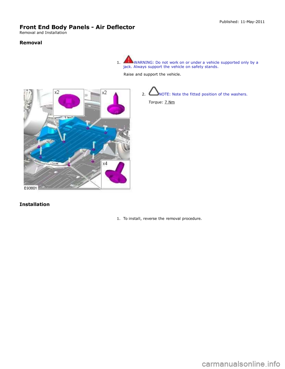
Front End Body Panels - Air Deflector
Removal and Installation
Removal Published: 11-May-2011
1. WARNING: Do not work on or under a vehicle supported only by a
jack. Always support the vehicle on safety stands.
Raise and support the vehicle.
Installation
2. NOTE: Note the fitted position of the washers.
Torque: 7 Nm
1. To install, reverse the removal procedure.
Page 2195 of 3039

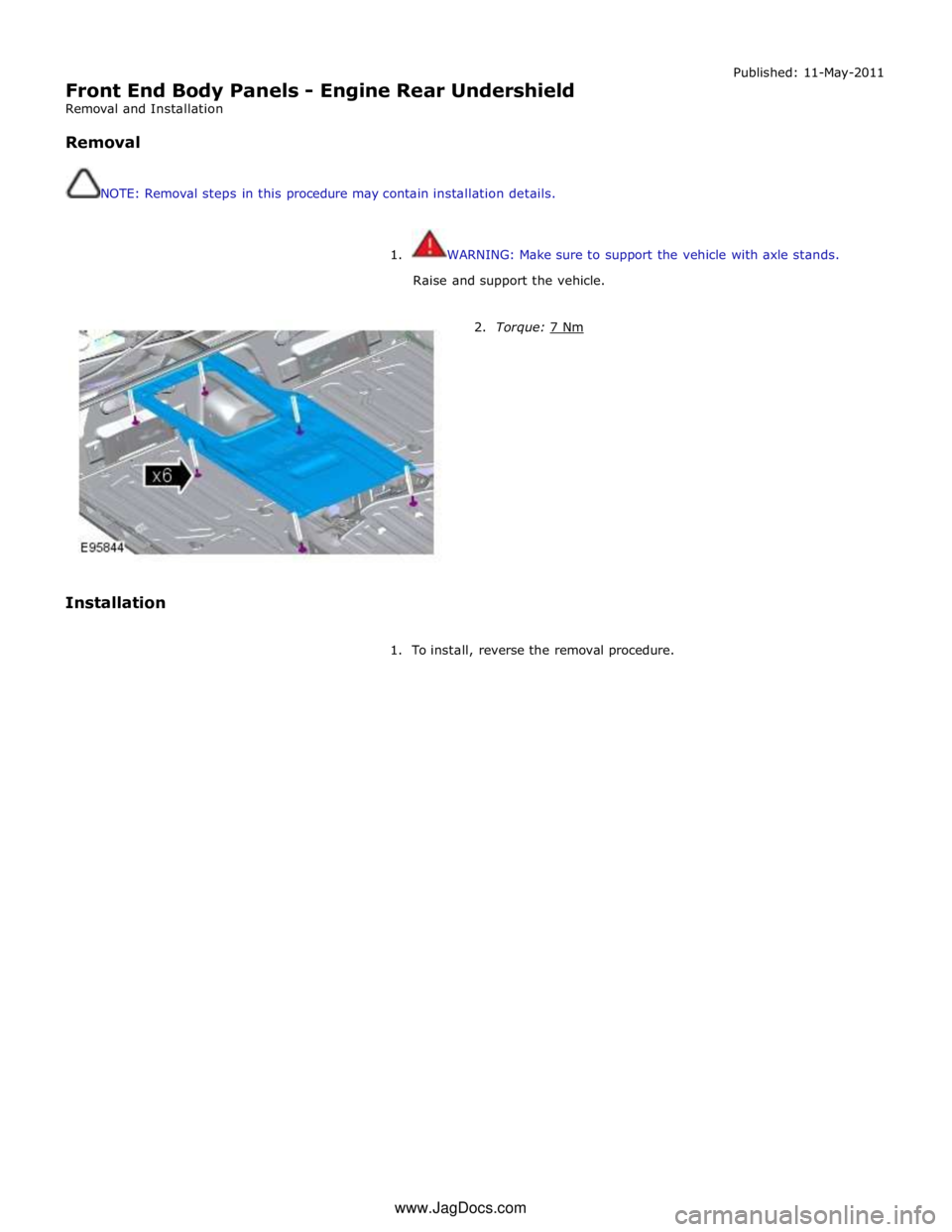
Front End Body Panels - Engine Rear Undershield
Removal and Installation
Removal
NOTE: Removal steps in this procedure may contain installation details. Published: 11-May-2011
1. WARNING: Make sure to support the vehicle with axle stands.
Raise and support the vehicle.
Installation
2. Torque: 7 Nm
1. To install, reverse the removal procedure. www.JagDocs.com
Page 2196 of 3039

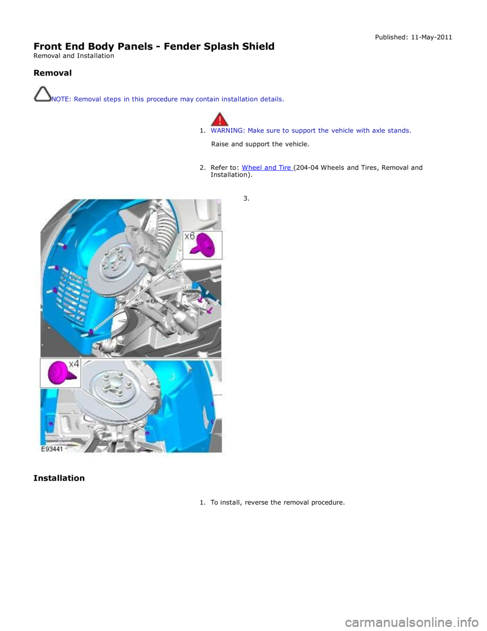
Front End Body Panels - Fender Splash Shield
Removal and Installation
Removal
NOTE: Removal steps in this procedure may contain installation details. Published: 11-May-2011
1. WARNING: Make sure to support the vehicle with axle stands.
Raise and support the vehicle.
2. Refer to: Wheel and Tire (204-04 Wheels and Tires, Removal and Installation).
3.
Installation
1. To install, reverse the removal procedure.