2010 JAGUAR XFR warning
[x] Cancel search: warningPage 2029 of 3039
Bulb Type Rating Reverse lamps - All markets PS19W 19W Licence plate lamps - All markets W5W 5W LIGHTING CONTROL SWITCH
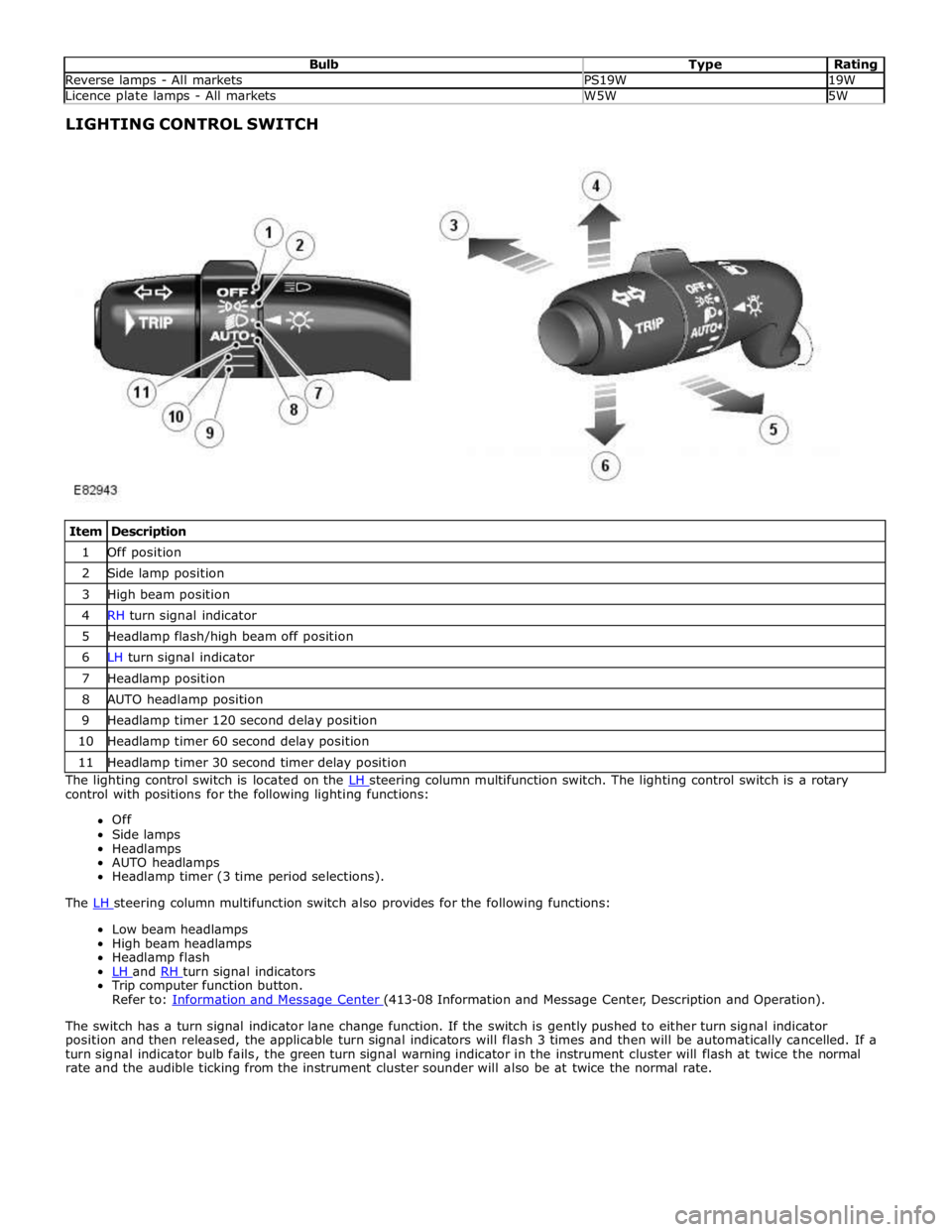
Item Description 1 Off position 2 Side lamp position 3 High beam position 4 RH turn signal indicator 5 Headlamp flash/high beam off position 6 LH turn signal indicator 7 Headlamp position 8 AUTO headlamp position 9 Headlamp timer 120 second delay position 10 Headlamp timer 60 second delay position 11 Headlamp timer 30 second timer delay position The lighting control switch is located on the LH steering column multifunction switch. The lighting control switch is a rotary control with positions for the following lighting functions:
Off
Side lamps
Headlamps
AUTO headlamps
Headlamp timer (3 time period selections).
The LH steering column multifunction switch also provides for the following functions: Low beam headlamps
High beam headlamps
Headlamp flash
LH and RH turn signal indicators Trip computer function button.
Refer to: Information and Message Center (413-08 Information and Message Center, Description and Operation).
The switch has a turn signal indicator lane change function. If the switch is gently pushed to either turn signal indicator
position and then released, the applicable turn signal indicators will flash 3 times and then will be automatically cancelled. If a
turn signal indicator bulb fails, the green turn signal warning indicator in the instrument cluster will flash at twice the normal
rate and the audible ticking from the instrument cluster sounder will also be at twice the normal rate.
Page 2032 of 3039
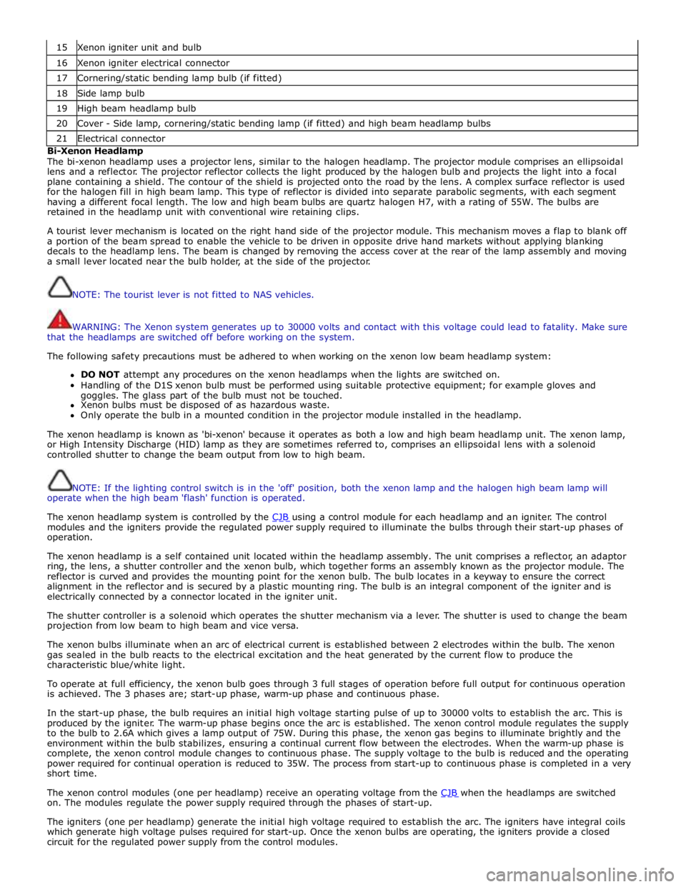
15 Xenon igniter unit and bulb 16 Xenon igniter electrical connector 17 Cornering/static bending lamp bulb (if fitted) 18 Side lamp bulb 19 High beam headlamp bulb 20 Cover - Side lamp, cornering/static bending lamp (if fitted) and high beam headlamp bulbs 21 Electrical connector Bi-Xenon Headlamp
The bi-xenon headlamp uses a projector lens, similar to the halogen headlamp. The projector module comprises an ellipsoidal
lens and a reflector. The projector reflector collects the light produced by the halogen bulb and projects the light into a focal
plane containing a shield. The contour of the shield is projected onto the road by the lens. A complex surface reflector is used
for the halogen fill in high beam lamp. This type of reflector is divided into separate parabolic segments, with each segment
having a different focal length. The low and high beam bulbs are quartz halogen H7, with a rating of 55W. The bulbs are
retained in the headlamp unit with conventional wire retaining clips.
A tourist lever mechanism is located on the right hand side of the projector module. This mechanism moves a flap to blank off
a portion of the beam spread to enable the vehicle to be driven in opposite drive hand markets without applying blanking
decals to the headlamp lens. The beam is changed by removing the access cover at the rear of the lamp assembly and moving
a small lever located near the bulb holder, at the side of the projector.
NOTE: The tourist lever is not fitted to NAS vehicles.
WARNING: The Xenon system generates up to 30000 volts and contact with this voltage could lead to fatality. Make sure
that the headlamps are switched off before working on the system.
The following safety precautions must be adhered to when working on the xenon low beam headlamp system:
DO NOT attempt any procedures on the xenon headlamps when the lights are switched on.
Handling of the D1S xenon bulb must be performed using suitable protective equipment; for example gloves and
goggles. The glass part of the bulb must not be touched.
Xenon bulbs must be disposed of as hazardous waste.
Only operate the bulb in a mounted condition in the projector module installed in the headlamp.
The xenon headlamp is known as 'bi-xenon' because it operates as both a low and high beam headlamp unit. The xenon lamp,
or High Intensity Discharge (HID) lamp as they are sometimes referred to, comprises an ellipsoidal lens with a solenoid
controlled shutter to change the beam output from low to high beam.
NOTE: If the lighting control switch is in the 'off' position, both the xenon lamp and the halogen high beam lamp will
operate when the high beam 'flash' function is operated.
The xenon headlamp system is controlled by the CJB using a control module for each headlamp and an igniter. The control modules and the igniters provide the regulated power supply required to illuminate the bulbs through their start-up phases of
operation.
The xenon headlamp is a self contained unit located within the headlamp assembly. The unit comprises a reflector, an adaptor
ring, the lens, a shutter controller and the xenon bulb, which together forms an assembly known as the projector module. The
reflector is curved and provides the mounting point for the xenon bulb. The bulb locates in a keyway to ensure the correct
alignment in the reflector and is secured by a plastic mounting ring. The bulb is an integral component of the igniter and is
electrically connected by a connector located in the igniter unit.
The shutter controller is a solenoid which operates the shutter mechanism via a lever. The shutter is used to change the beam
projection from low beam to high beam and vice versa.
The xenon bulbs illuminate when an arc of electrical current is established between 2 electrodes within the bulb. The xenon
gas sealed in the bulb reacts to the electrical excitation and the heat generated by the current flow to produce the
characteristic blue/white light.
To operate at full efficiency, the xenon bulb goes through 3 full stages of operation before full output for continuous operation
is achieved. The 3 phases are; start-up phase, warm-up phase and continuous phase.
In the start-up phase, the bulb requires an initial high voltage starting pulse of up to 30000 volts to establish the arc. This is
produced by the igniter. The warm-up phase begins once the arc is established. The xenon control module regulates the supply
to the bulb to 2.6A which gives a lamp output of 75W. During this phase, the xenon gas begins to illuminate brightly and the
environment within the bulb stabilizes, ensuring a continual current flow between the electrodes. When the warm-up phase is
complete, the xenon control module changes to continuous phase. The supply voltage to the bulb is reduced and the operating
power required for continual operation is reduced to 35W. The process from start-up to continuous phase is completed in a very
short time.
The xenon control modules (one per headlamp) receive an operating voltage from the CJB when the headlamps are switched on. The modules regulate the power supply required through the phases of start-up.
The igniters (one per headlamp) generate the initial high voltage required to establish the arc. The igniters have integral coils
which generate high voltage pulses required for start-up. Once the xenon bulbs are operating, the igniters provide a closed
circuit for the regulated power supply from the control modules.
Page 2036 of 3039
Rear Fog Lamp
The rear fog lamps are located in separate units attached to the luggage compartment lid. The rear fog lamps each use 3 high
intensity LED's. The fog lamp locates in a recess in the luggage compartment lid has a seal to prevent the ingress of water into the luggage compartment. The lamp is secured in the recess with a metal securing clip. The rear fog lamp is activated
using a button located on the auxiliary lighting switch in the instrument panel.
LICENCE PLATE LAMPS
Two licence plate lamps are located in the luggage compartment lid trim finisher. One is located adjacent to the emergency
luggage compartment lid release key barrel cover and the other is adjacent to the rear view camera (if fitted). The licence plate
lamps are active at all times when the side lamps are operating. Each lamp can be removed from the finisher by inserting a
wide, flat screwdriver blade or similar tool in a slot between the lamp lens and the finisher and gently levering the lamp from
the surround. The bulb is a push fit in a holder which in turn is a press fit in the lamp housing.
HIGH MOUNTED STOP LAMP
The high mounted stop lamp is located at the bottom of the rear windshield. The lamp is secured to a bezel in the parcel shelf
with 2 screws.
The high mounted stop lamp uses 12, red colored LED's which illuminate through a clear lens. The high mounted stop lamp functionality is the same as that described for the stop lamps.
TURN SIGNAL INDICATOR SIDE REPEATER LAMPS
The turn signal indicator side repeaters are located in each door mirror. On vehicles from 10MY the lamp is an LED unit which illuminates in an orange color. The LED unit is secured to the mirror bezel with 2 screws and is connected to the mirror wiring harness with a 2 pin connector.
The side repeaters have the same functionality and operate in conjunction with the front and rear turn signal indicators and
the hazard warning flashers.
HAZARD FLASHERS
The hazard flashers are activated by a non-latching switch located in the switch pack located in the center of the instrument
panel. The hazard flashers operate at all times when selected and operate independent of the ignition mode.
When the hazard flashers are selected on by the driver, a ground path is momentarily completed to the CJB which activates the front and rear and side repeater turn signal indicators. A second press of the switch is sensed by the CJB and the hazard flasher are deactivated. When the hazard flashers are active, they override any request for turn signal indicator operation.
The hazard flashers can also be activated by a crash signal from the RCM. Refer to: Air Bag and Safety Belt Pretensioner Supplemental Restraint System (SRS) (501-20B Supplemental Restraint System, Description and Operation).
Page 2037 of 3039
Exterior Lighting - Headlamps
Diagnosis and Testing
Principles of Operation Published: 11-Jul-2014
For a detailed description of the exterior lighting system, refer to the relevant Description and Operation section in the
workshop manual. REFER to: (417-01 Exterior Lighting)
Exterior Lighting (Description and Operation), Exterior Lighting (Description and Operation), Exterior Lighting (Description and Operation).
Safety Information
WARNINGS:
The Xenon Headlamp system generates up to 28,000 volts. Make sure that the headlamps are switched off before
working on the system. Failure to follow this instruction may lead to fatality.
The following safety precautions must be followed when working on the Xenon Headlamp system:
DO NOT attempt any procedures on the Xenon Headlamps or circuits when the system is energized.
Handling of the xenon bulb must be performed using suitable protective equipment, e.g. gloves and goggles. The glass
part of the bulb must not be touched.
Only operate the lamp in a mounted condition in the reflector.
All safety procedures and precautions must be followed to prevent personal injury.
CAUTION: Xenon bulbs must be disposed of as hazardous waste.
There are instructions on the correct procedures for Xenon Headlamp System repairs in the manual, refer to section 100-00 -
General Information, Standard Workshop Practices of the workshop manual.
Inspection and Verification
CAUTION: Diagnosis by substitution from a donor vehicle is NOT acceptable. Substitution of control modules does not
guarantee confirmation of a fault, and may also cause additional faults in the vehicle being tested and/or the donor vehicle.
1. Verify the customer concern.
2. Visually inspect for obvious signs of damage.
3. If an obvious cause for an observed or reported concern is found, correct the cause (if possible) before proceeding to
the next step.
4. If the cause is not visually evident, check for Diagnostic Trouble Codes (DTCs) and refer to DTC Index.
Symptom Chart
Symptom Possible Causes Action Low beam lamp(s)
inoperative
Bulb failure
Fuse(s) blown
Circuit fault
Lighting control switch
fault
Left-hand steering
column multifunction
switch fault Check the bulb and fuse condition (see visual inspection). Check the
headlamp circuits. Check the lighting control switch function. Check the
left-hand steering column multifunction switch operation. Refer to the
electrical guides. Check for DTCs indicating a headlamp or related circuit
fault. High beam lamp(s)
inoperative Electrical
Headlamp Leveling Module (HLM)
Bulb(s)
Photocell(s)
Ballast
Wiring harness/electrical connectors
Fuse(s) Visual Inspection
Page 2038 of 3039

Symptom Possible Causes Action Low beam lamp(s)
dim
Incorrect bulb rating
Tourist lever set in the
wrong position
Circuit fault
Lighting control switch
fault
Left-hand steering
column multifunction
switch fault Check the bulb condition and rating. Check the tourist lever is set
correctly. Check the headlamp circuits. Check the lighting control switch
function. Check the left-hand steering column multifunction switch
function. Refer to the electrical guides. High beam lamp(s)
dim Low beam lamp(s)
stuck on
Circuit fault
Lighting control switch
fault
Left-hand steering
column multifunction
switch fault
Headlamp timer
function fault Check the headlamp circuits. Check the lighting control switch function.
Check the left-hand steering column multifunction switch operation. Check
the headlamp timer function. Refer to the electrical guides. Check for DTCs
indicating a headlamp circuit fault High beam lamp(s)
stuck on Headlamp low/high
beam switching
function inoperative
Circuit fault
Left-hand steering
column multifunction
switch fault
Xenon lamp shutter
mechanism fault Check the headlamp circuits. Check the left-hand steering column
multifunction switch operation. Check the xenon lamp shutter mechanism
operation. Refer to the electrical guides. Check for DTCs indicating a
headlamp circuit fault Warning lamp(s)
inoperative
Fuse(s) blown
Lighting control switch
fault
Left-hand steering
column multifunction
switch inoperative
Circuit fault
Instrument cluster
fault Check the fuse(s) (see visual inspection). Check the lighting control switch
function. Check the left-hand steering column multifunction switch
function. Check the warning lamp circuits. Refer to the electrical guides.
Check for DTCs indicating an instrument cluster or CAN system fault. Headlamp Wet -
Internal
Condensation
Water Ingress Check for outstanding Technical Service Bulletins (TSBs) relating to
'Headlamp Internal Condensation'. Carry out the instructions in the service
bulletin to determine if the fault is related to condensation or water ingress. DTC Index
For a list of Diagnostic Trouble Codes (DTCs) that could be logged on this vehicle, please refer to Section 100-00. REFER to:
Diagnostic Trouble Code (DTC) Index - DTC: Headlamp Control Module (HCM) (100-00 General Information, Description and Operation).
Page 2045 of 3039
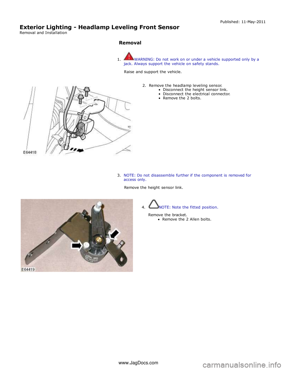
Exterior Lighting - Headlamp Leveling Front Sensor
Removal and Installation
Removal Published: 11-May-2011
1. WARNING: Do not work on or under a vehicle supported only by a
jack. Always support the vehicle on safety stands.
Raise and support the vehicle.
2. Remove the headlamp leveling sensor.
Disconnect the height sensor link.
Disconnect the electrical connector.
Remove the 2 bolts.
3. NOTE: Do not disassemble further if the component is removed for
access only.
Remove the height sensor link.
4. NOTE: Note the fitted position.
Remove the bracket.
Remove the 2 Allen bolts. www.JagDocs.com
Page 2047 of 3039
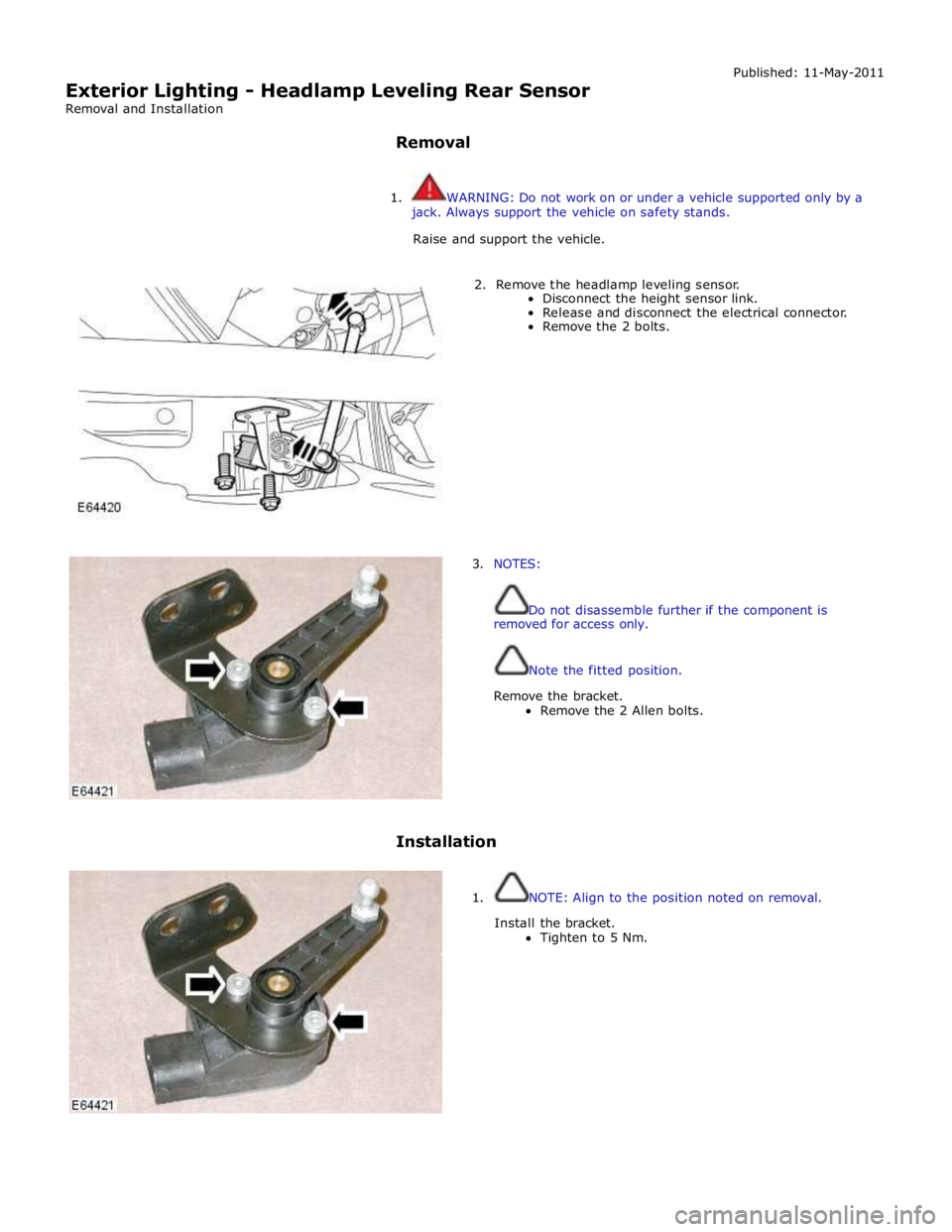
Exterior Lighting - Headlamp Leveling Rear Sensor
Removal and Installation
Removal Published: 11-May-2011
1. WARNING: Do not work on or under a vehicle supported only by a
jack. Always support the vehicle on safety stands.
Raise and support the vehicle.
2. Remove the headlamp leveling sensor.
Disconnect the height sensor link.
Release and disconnect the electrical connector.
Remove the 2 bolts.
3. NOTES:
Do not disassemble further if the component is
removed for access only.
Note the fitted position.
Remove the bracket.
Remove the 2 Allen bolts.
Installation
1. NOTE: Align to the position noted on removal.
Install the bracket.
Tighten to 5 Nm.
Page 2060 of 3039
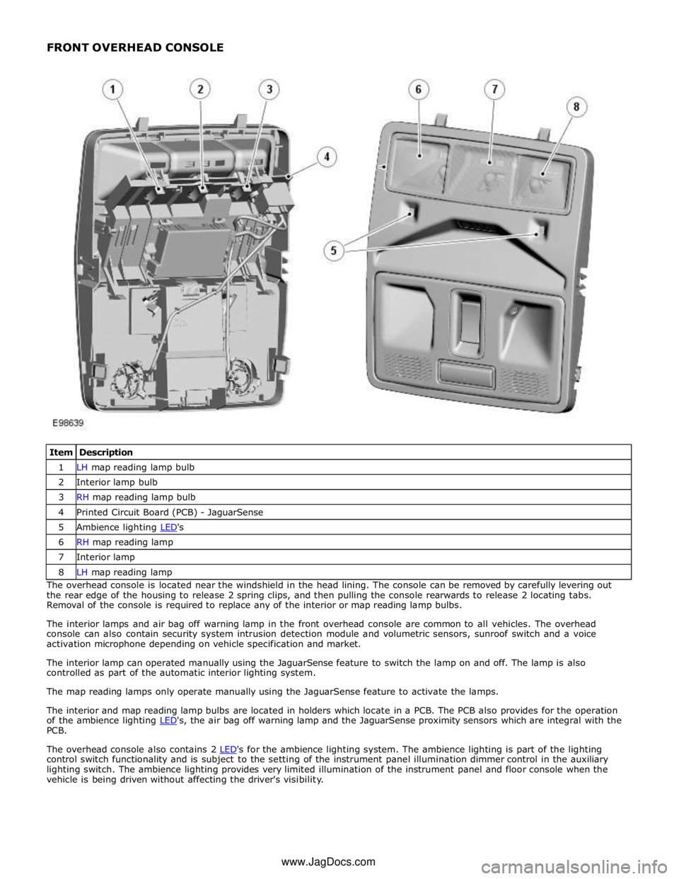
1 LH map reading lamp bulb 2 Interior lamp bulb 3 RH map reading lamp bulb 4 Printed Circuit Board (PCB) - JaguarSense 5 Ambience lighting LED's 6 RH map reading lamp 7 Interior lamp 8 LH map reading lamp The overhead console is located near the windshield in the head lining. The console can be removed by carefully levering out
the rear edge of the housing to release 2 spring clips, and then pulling the console rearwards to release 2 locating tabs.
Removal of the console is required to replace any of the interior or map reading lamp bulbs.
The interior lamps and air bag off warning lamp in the front overhead console are common to all vehicles. The overhead
console can also contain security system intrusion detection module and volumetric sensors, sunroof switch and a voice
activation microphone depending on vehicle specification and market.
The interior lamp can operated manually using the JaguarSense feature to switch the lamp on and off. The lamp is also
controlled as part of the automatic interior lighting system.
The map reading lamps only operate manually using the JaguarSense feature to activate the lamps.
The interior and map reading lamp bulbs are located in holders which locate in a PCB. The PCB also provides for the operation
of the ambience lighting LED's, the air bag off warning lamp and the JaguarSense proximity sensors which are integral with the PCB.
The overhead console also contains 2 LED's for the ambience lighting system. The ambience lighting is part of the lighting control switch functionality and is subject to the setting of the instrument panel illumination dimmer control in the auxiliary
lighting switch. The ambience lighting provides very limited illumination of the instrument panel and floor console when the
vehicle is being driven without affecting the driver's visibility. www.JagDocs.com