Page 1710 of 3039

control switch on the integrated control panel or the + and - soft buttons on the touch screen display (TSD). The ATC module also adjusts blower speed to compensate for the ram effect on inlet air produced by forward movement of the vehicle. As
vehicle speed and ram effect increases, blower motor speed is reduced, and vice versa.
Air Distribution Control
Two air distribution doors are used to direct air into the passenger compartment. The doors are operated by stepper motors,
which are controlled by the ATC module using LIN bus messages.
When the A/C system is in automatic mode, the ATC module automatically controls air distribution into the passenger compartment in line with its 'comfort' algorithm. Automatic control is overridden if any of the TSD air distribution soft buttons
are selected. Air distribution in the passenger compartment will remain as selected until the 'Auto' switch is pressed or a
different manual selection is made.
A/C Compressor Control
When A/C is selected the ATC module maintains the evaporator at an operating temperature that varies with the passenger compartment cooling requirements. If the requirement for cooled air decreases, the ATC module raises the evaporator operating temperature by reducing the flow of refrigerant provided by the A/C compressor. The ATC module closely controls the rate of temperature increase to avoid introducing moisture into the passenger compartment.
If the requirement for cooled air increases, the ATC module lowers the evaporator operating temperature by increasing the flow of refrigerant provided by the A/C compressor.
When A/C is off, the compressor current signal supplied by the ATC module holds the A/C compressor solenoid valve in the minimum flow position, effectively switching off the A/C function.
The ATC module incorporates limits for the operating pressure of the refrigerant system. If the system approaches the high pressure limit, the compressor current signal is progressively reduced until the system pressure decreases. If the system falls
below the low pressure limit, the compressor current signal is held at its lowest setting so that the A/C compressor is maintained at its minimum stroke. This avoids depletion of the lubricant from the A/C compressor.
A/C Compressor Torque
The ATC module transmits refrigerant pressure and A/C compressor current values to the ECM (engine control module) over the medium speed then high speed CAN bus, using the CJB as a gateway. The ECM uses these values to calculate the torque being used to drive the A/C compressor. The ECM compares the calculated value with its allowable value and if necessary forces the ATC module to inhibit the A/C compressor by transmitting the 'ACClutchInhibit' CAN message. This forces the ATC module to reduce the drive current to the A/C compressor solenoid valve, which reduces refrigerant flow. This in turn reduces the torque required to drive the A/C compressor.
By reducing the maximum A/C compressor torque, the ECM is able to reduce the load on the engine when it needs to maintain vehicle performance or cooling system integrity.
Cooling Fan Control
The ATC module determines the amount of condenser cooling required from the refrigerant pressure sensor, since there is a direct relationship between the temperature and pressure of the refrigerant. The cooling requirement is broadcast to the ECM on the medium speed CAN bus. The ECM then controls the temperature of the condenser using the cooling fan.
Programmed Defrost
The programmed defrost DEF switch is located on the integrated control panel. When the switch is pressed, the ATC module instigates the programmed defrost function. When selected, the ATC module configures the system as follows:
Automatic mode off.
A/C on. Selected temperature unchanged.
Air inlet set to fresh air.
Air distribution set to windshield.
Blower speed set to level 6.
Windshield heater (where fitted) and rear window heater on.
The programmed defrost function can be cancelled by one of the following:
Selecting any air distribution switch on the TSD.
Pressing the AUTO switch on the integrated control panel.
A second press of the DEF button.
Switching the ignition OFF.
The blower speed can be adjusted without terminating the programmed defrost function.
Rear Window Heater
Rear window heater operation is only enabled when the engine is running. The ATC module controls operation of the rear window heater using a relay in the RJB. When rear window heater operation is required, the ATC module broadcasts a message to the RJB on the medium speed CAN bus. On receipt of the message, the RJB energizes the relay by providing a ground path for the relay coil. This allows a battery feed to flow across the relay to power the rear window heater element.
Page 1712 of 3039

bus. Temperature control for the heater element is provided by the steering wheel heater control module which receives a
temperature feedback signal from a NTC (negative temperature coefficient) thermistor located within the steering wheel.
ATC Module Component Description
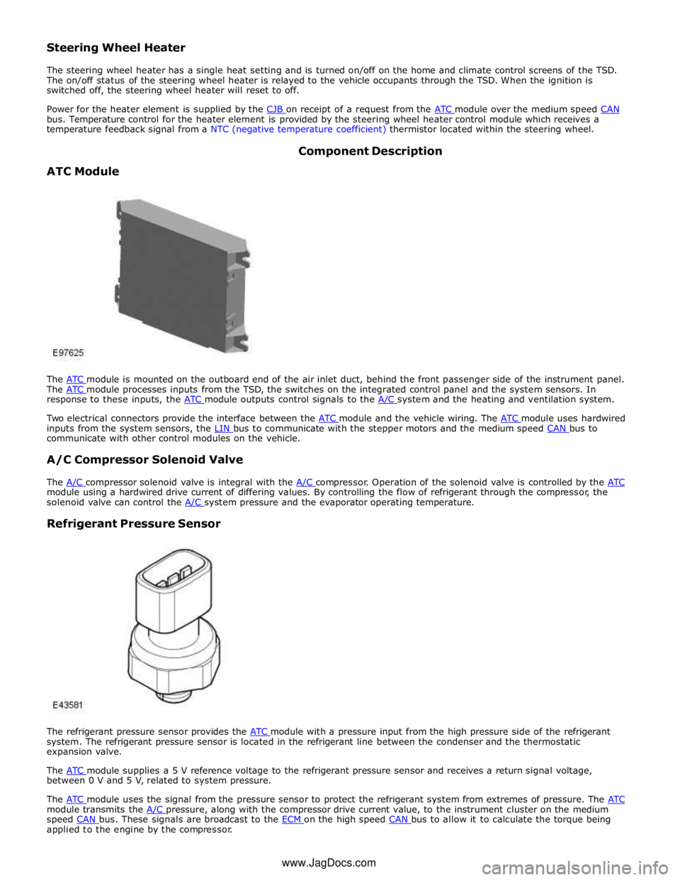
The ATC module is mounted on the outboard end of the air inlet duct, behind the front passenger side of the instrument panel. The ATC module processes inputs from the TSD, the switches on the integrated control panel and the system sensors. In response to these inputs, the ATC module outputs control signals to the A/C system and the heating and ventilation system.
Two electrical connectors provide the interface between the ATC module and the vehicle wiring. The ATC module uses hardwired inputs from the system sensors, the LIN bus to communicate with the stepper motors and the medium speed CAN bus to communicate with other control modules on the vehicle.
A/C Compressor Solenoid Valve
The A/C compressor solenoid valve is integral with the A/C compressor. Operation of the solenoid valve is controlled by the ATC module using a hardwired drive current of differing values. By controlling the flow of refrigerant through the compressor, the
solenoid valve can control the A/C system pressure and the evaporator operating temperature.
Refrigerant Pressure Sensor
The refrigerant pressure sensor provides the ATC module with a pressure input from the high pressure side of the refrigerant system. The refrigerant pressure sensor is located in the refrigerant line between the condenser and the thermostatic
expansion valve.
The ATC module supplies a 5 V reference voltage to the refrigerant pressure sensor and receives a return signal voltage, between 0 V and 5 V, related to system pressure.
The ATC module uses the signal from the pressure sensor to protect the refrigerant system from extremes of pressure. The ATC module transmits the A/C pressure, along with the compressor drive current value, to the instrument cluster on the medium speed CAN bus. These signals are broadcast to the ECM on the high speed CAN bus to allow it to calculate the torque being applied to the engine by the compressor. www.JagDocs.com
Page 1721 of 3039
Climate Control - Blower Motor Control Module
Removal and Installation
Removal
NOTE: Removal steps in this procedure may contain installation details. Published: 11-May-2011
1. Refer to: Battery Disconnect and Connect (414-01 Battery, Mounting and Cables, General Procedures).
Installation
2. CAUTION: Take extra care not to damage the clips or
screw threads. Failure to follow this instruction may result
in damage to the climate control assembly.
NOTE: RHD illustration shown, LHD is similar.
3. Torque: 1.3 Nm
1. To install, reverse the removal procedure.
Page 1725 of 3039
Climate Control - Climate Control Assembly
Removal and Installation
Removal
NOTES:
Removal steps in this procedure may contain installation details.
RHD illustration shown, LHD is similar. Published: 11-May-2011
1. Refer to: Battery Disconnect and Connect (414-01 Battery, Mounting and Cables, General Procedures).
2. WARNING: Make sure to support the vehicle with axle stands.
Raise and support the vehicle.
3. Refer to: Instrument Panel Console (501-12 Instrument Panel and Console, Removal and Installation).
4.
5. Torque: 9 Nm
Page 1726 of 3039
6. CAUTION: Be prepared to collect escaping coolant.
Torque: 9 Nm
7.
Installation
1. To install, reverse the removal procedure.
Page 1727 of 3039
Climate Control - Climate Control Module
Removal and Installation
Removal
NOTE: Removal steps in this procedure may contain installation details. Published: 11-May-2011
1. Refer to: Battery Disconnect and Connect (414-01 Battery, Mounting and Cables, General Procedures).
2. Refer to: Instrument Panel Console (501-12 Instrument Panel and Console, Removal and Installation).
Installation
3. CAUTIONS:
Take extra care not to damage the clips or screw
threads. Failure to follow this instruction may result in
damage to the climate control assembly.
Make sure that the component is correctly located on
the locating dowels.
NOTE: RHD illustration shown, LHD is similar.
Torque: 1.3 Nm
1. To install, reverse the removal procedure. www.JagDocs.com
Page 1728 of 3039
Climate Control - Defrost Vent/Register Blend Door Actuator
Removal and Installation
Removal
NOTE: Removal steps in this procedure may contain installation details. Published: 11-May-2011
1. Refer to: Battery Disconnect and Connect (414-01, General Procedures).
2. Refer to: Instrument Panel Console (501-12, Removal and Installation).
Installation
3. CAUTIONS:
Take extra care not to damage the clips or screw
threads. Failure to follow this instruction may result in
damage to the climate control assembly.
Make sure that the component is correctly located on
the locating dowels.
NOTE: RHD illustration shown, LHD is similar.
Torque: 1.3 Nm
1. To install, reverse the removal procedure.
Page 1733 of 3039
Climate Control - Evaporator
Removal and Installation
Removal
NOTE: Removal steps in this procedure may contain installation details.
All vehicles Published: 11-May-2011
1. Refer to: Battery Disconnect and Connect (414-01 Battery, Mounting and Cables, General Procedures).
2. Refer to: Heater Core and Evaporator Core Housing (412-01 Climate Control, Removal and Installation).
3. Refer to: Thermostatic Expansion Valve (412-01 Climate Control, Removal and Installation).
Right-hand drive vehicles
4. CAUTION: Take extra care not to damage the clips or
screw threads. Failure to follow this instruction may result
in damage to the climate control assembly.
Torque: 1.3 Nm
5. Torque: 1.3 Nm