Page 1513 of 3039
8.
9.
10. CAUTION: Only rotate the crankshaft clockwise.
NOTE: Make sure that the alignment mark is visable
through the inspection hole as illustrated.
Torque: 63 Nm
Page 1515 of 3039
14.
15.
16. CAUTION: Install new o-ring seals
Torque: 10 Nm
17.
Refer to: Catalytic Converter LH (309-00C Exhaust System - V8 5.0L Petrol/V8 S/C 5.0L Petrol, Removal and Installation).
18. Refer to: Catalytic Converter RH (309-00C Exhaust System - V8 5.0L Petrol/V8 S/C 5.0L Petrol, Removal and Installation).
19. Refer to: Battery Disconnect and Connect (414-01 Battery, Mounting and Cables, General Procedures). www.JagDocs.com
Page 1521 of 3039

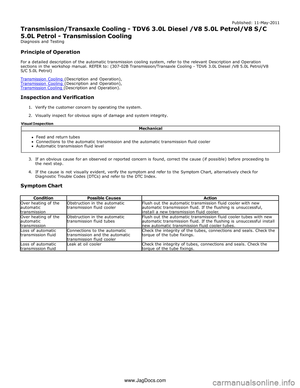
Transmission Cooling (Description and Operation), Transmission Cooling (Description and Operation).
Inspection and Verification
1. Verify the customer concern by operating the system.
2. Visually inspect for obvious signs of damage and system integrity.
3. If an obvious cause for an observed or reported concern is found, correct the cause (if possible) before proceeding to
the next step.
4. If the cause is not visually evident, verify the symptom and refer to the Symptom Chart, alternatively check for
Diagnostic Trouble Codes (DTCs) and refer to the DTC Index.
Symptom Chart
Condition Possible Causes Action Over heating of the
automatic
transmission Obstruction in the automatic
transmission fluid cooler Flush out the automatic transmission fluid cooler with new
automatic transmission fluid. If the flushing is unsuccessful,
install a new transmission fluid cooler. Over heating of the
automatic
transmission Obstruction in the automatic
transmission fluid tubes Flush out the automatic transmission fluid cooler tubes with new
automatic transmission fluid. If the flushing is unsuccessful install
new automatic transmission fluid cooler tubes. Loss of automatic
transmission fluid Connections to the automatic
transmission and the automatic
transmission fluid cooler Check the integrity of the tubes, connections and seals. Check the
torque of the tube fixings. Loss of automatic
transmission fluid Leak at oil cooler
Check the integrity of tubes, connections and seals. Check the torque of the tube fixings. Mechanical
Feed and return tubes
Connections to the automatic transmission and the automatic transmission fluid cooler
Automatic transmission fluid level Visual Inspection
www.JagDocs.com
Page 1524 of 3039
Published: 11-May-2011
Transmission/Transaxle Cooling - TDV6 3.0L Diesel /V8 5.0L Petrol/V8 S/C 5.0L Petrol - Transmission Fluid Cooler Tubes V8 5.0L Petrol/V8 S/C 5.0L
Petrol
Removal and Installation
Removal
NOTE: Removal steps in this procedure may contain installation details.
1. WARNING: Make sure to support the vehicle with axle stands.
Raise and support the vehicle.
2. Refer to: Transmission Fluid Drain and Refill (307-01A Automatic Transmission/Transaxle - V6 3.0L Petrol, General Procedures).
3. CAUTIONS:
Be prepared to collect escaping fluids.
Make sure that all openings are sealed. Use new
blanking caps.
4. Torque: 11 Nm www.JagDocs.com
Page 1551 of 3039
6. CAUTION: Make sure that the exhaust system is
supported with suitable retaining straps.
Tighten the top retaining nut first.
Torque:
Top nut 40 Nm Bottom nut 40 Nm
7. CAUTION: Make sure that the exhaust system is
supported with suitable retaining straps.
Torque: 55 Nm
8. CAUTIONS:
Make sure the anti-seize compound does not contact
the catalyst monitor sensor tip.
If accidentally dropped or knocked install a new
sensor.
NOTES:
Do not disassemble further if the component is
removed for access only.
If the original sensor is to be installed, apply lubricant
meeting specification ESE-M12A4-A to the thread of the
sensor.
Torque: 48 Nm
Installation
1. To install, reverse the removal procedure.
Page 1554 of 3039
6. CAUTION: Make sure that the exhaust system is
supported with suitable retaining straps.
Tighten the top retaining nut first.
Torque:
Top nut 40 Nm Bottom nut 40 Nm
7. CAUTION: Make sure that the exhaust system is
supported with suitable retaining straps.
Torque: 55 Nm
8. CAUTIONS:
Make sure the anti-seize compound does not contact
the catalyst monitor sensor tip.
If accidentally dropped or knocked install a new
sensor.
NOTES:
Do not disassemble further if the component is
removed for access only.
If the original sensor is to be installed, apply lubricant
meeting specification ESE-M12A4-A to the thread of the
sensor.
Torque: 48 Nm
Installation
1. To install, reverse the removal procedure.
Page 1556 of 3039
Published: 11-May-2011
Exhaust System - V8 5.0L Petrol/V8 S/C 5.0L Petrol - Exhaust Sound
Enhancement Valve
Removal and Installation
Removal
WARNING: Observe due care when working near a hot exhaust system.
NOTES:
The exhaust sound enhancement valve is an integeral part of the muffler and cannot be serviced separately.
Removal steps in this procedure may contain installation details.
1. WARNING: Make sure to support the vehicle with axle stands.
Raise and support the vehicle.
Installation
2. CAUTION: Make sure that these components are
installed to the noted removal position.
Torque:
M8 25 Nm M10 55 Nm
1. To install, reverse the removal procedure.
Page 1558 of 3039
7. CAUTION: Make sure that the exhaust system is
supported with suitable retaining straps.
Torque: 40 Nm
8. Torque: 40 Nm