2010 JAGUAR XFR reset
[x] Cancel search: resetPage 1793 of 3039
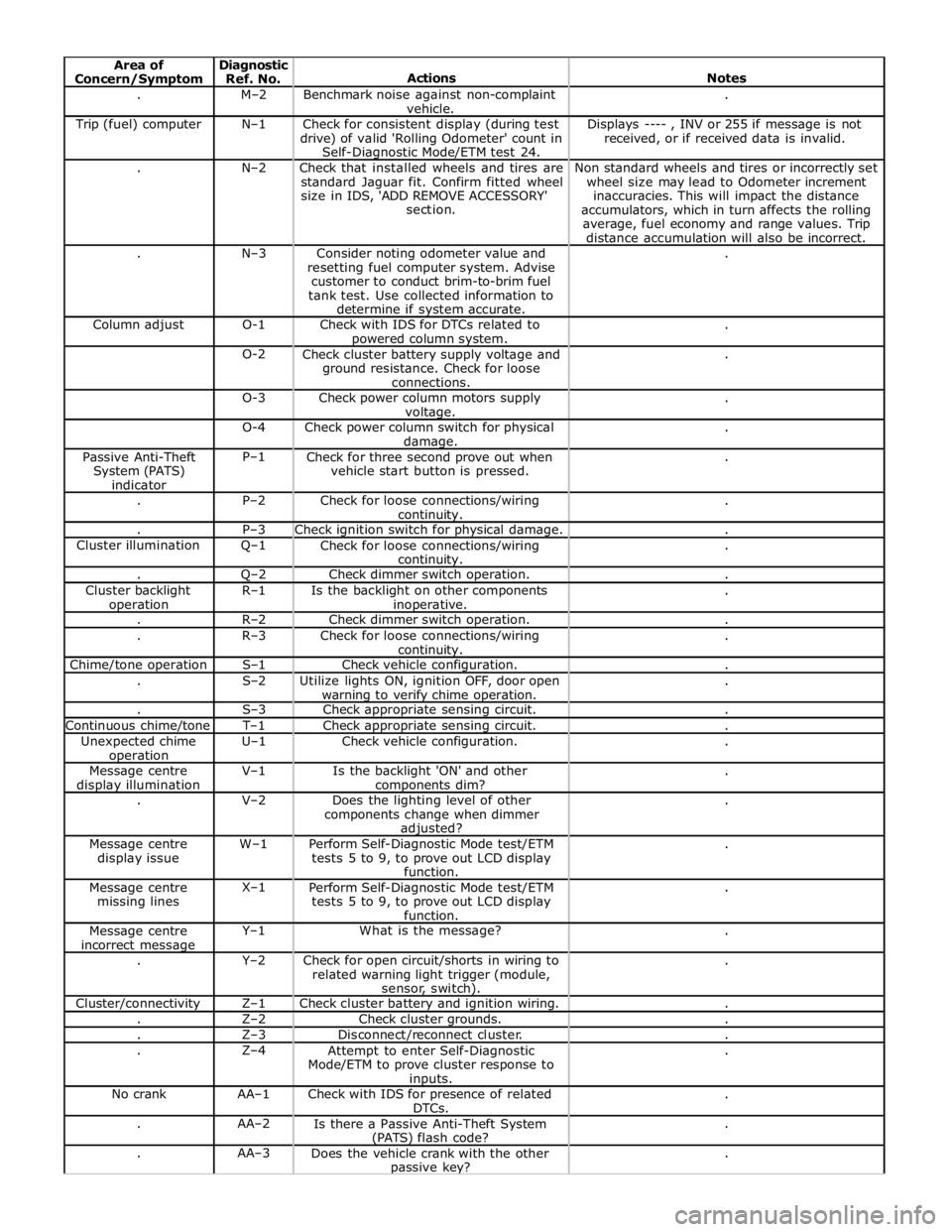
. M–2
Benchmark noise against non-complaint
vehicle. . Trip (fuel) computer N–1
Check for consistent display (during test
drive) of valid 'Rolling Odometer' count in
Self-Diagnostic Mode/ETM test 24. Displays ---- , INV or 255 if message is not
received, or if received data is invalid. . N–2
Check that installed wheels and tires are
standard Jaguar fit. Confirm fitted wheel
size in IDS, 'ADD REMOVE ACCESSORY'
section. Non standard wheels and tires or incorrectly set
wheel size may lead to Odometer increment
inaccuracies. This will impact the distance
accumulators, which in turn affects the rolling
average, fuel economy and range values. Trip
distance accumulation will also be incorrect. . N–3
Consider noting odometer value and
resetting fuel computer system. Advise
customer to conduct brim-to-brim fuel
tank test. Use collected information to
determine if system accurate. . Column adjust O-1
Check with IDS for DTCs related to powered column system. . O-2
Check cluster battery supply voltage and
ground resistance. Check for loose
connections. . O-3
Check power column motors supply voltage. . O-4
Check power column switch for physical damage. . Passive Anti-Theft
System (PATS)
indicator P–1
Check for three second prove out when
vehicle start button is pressed. . . P–2
Check for loose connections/wiring continuity. . . P–3 Check ignition switch for physical damage. . Cluster illumination Q–1
Check for loose connections/wiring continuity. . . Q–2 Check dimmer switch operation. . Cluster backlight operation R–1
Is the backlight on other components inoperative. . . R–2 Check dimmer switch operation. . . R–3
Check for loose connections/wiring continuity. . Chime/tone operation S–1 Check vehicle configuration. . . S–2
Utilize lights ON, ignition OFF, door open warning to verify chime operation. . . S–3 Check appropriate sensing circuit. . Continuous chime/tone T–1 Check appropriate sensing circuit. . Unexpected chime operation U–1 Check vehicle configuration. . Message centre display illumination V–1
Is the backlight 'ON' and other components dim? . . V–2
Does the lighting level of other
components change when dimmer adjusted? . Message centre
display issue W–1
Perform Self-Diagnostic Mode test/ETM
tests 5 to 9, to prove out LCD display
function. . Message centre
missing lines X–1
Perform Self-Diagnostic Mode test/ETM
tests 5 to 9, to prove out LCD display
function. . Message centre
incorrect message Y–1 What is the message? . . Y–2
Check for open circuit/shorts in wiring to
related warning light trigger (module,
sensor, switch). . Cluster/connectivity Z–1 Check cluster battery and ignition wiring. . . Z–2 Check cluster grounds. . . Z–3 Disconnect/reconnect cluster. . . Z–4
Attempt to enter Self-Diagnostic
Mode/ETM to prove cluster response to inputs. . No crank AA–1
Check with IDS for presence of related
DTCs. . . AA–2
Is there a Passive Anti-Theft System (PATS) flash code? . . AA–3
Does the vehicle crank with the other passive key? .
Page 1821 of 3039
Published: 11-May-2011
Information and Message Center - Information and Message Center - System
Operation and Component Description
Description and Operation
System Operation
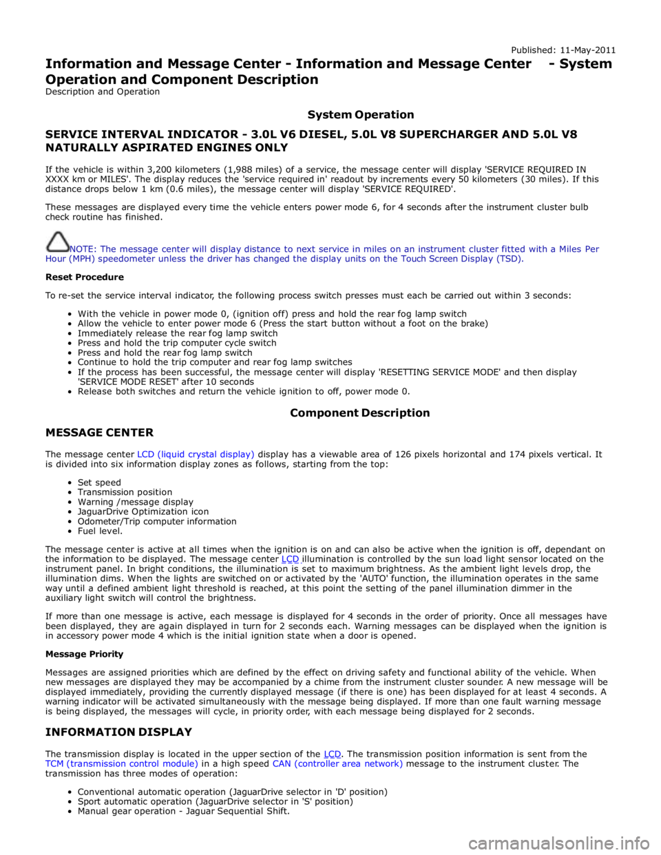
SERVICE INTERVAL INDICATOR - 3.0L V6 DIESEL, 5.0L V8 SUPERCHARGER AND 5.0L V8 NATURALLY ASPIRATED ENGINES ONLY
If the vehicle is within 3,200 kilometers (1,988 miles) of a service, the message center will display 'SERVICE REQUIRED IN
XXXX km or MILES'. The display reduces the 'service required in' readout by increments every 50 kilometers (30 miles). If this
distance drops below 1 km (0.6 miles), the message center will display 'SERVICE REQUIRED'.
These messages are displayed every time the vehicle enters power mode 6, for 4 seconds after the instrument cluster bulb
check routine has finished.
NOTE: The message center will display distance to next service in miles on an instrument cluster fitted with a Miles Per
Hour (MPH) speedometer unless the driver has changed the display units on the Touch Screen Display (TSD).
Reset Procedure
To re-set the service interval indicator, the following process switch presses must each be carried out within 3 seconds:
With the vehicle in power mode 0, (ignition off) press and hold the rear fog lamp switch
Allow the vehicle to enter power mode 6 (Press the start button without a foot on the brake)
Immediately release the rear fog lamp switch
Press and hold the trip computer cycle switch
Press and hold the rear fog lamp switch
Continue to hold the trip computer and rear fog lamp switches
If the process has been successful, the message center will display 'RESETTING SERVICE MODE' and then display
'SERVICE MODE RESET' after 10 seconds
Release both switches and return the vehicle ignition to off, power mode 0.
MESSAGE CENTER Component Description
The message center LCD (liquid crystal display) display has a viewable area of 126 pixels horizontal and 174 pixels vertical. It
is divided into six information display zones as follows, starting from the top:
Set speed
Transmission position
Warning /message display
JaguarDrive Optimization icon
Odometer/Trip computer information
Fuel level.
The message center is active at all times when the ignition is on and can also be active when the ignition is off, dependant on
the information to be displayed. The message center LCD illumination is controlled by the sun load light sensor located on the instrument panel. In bright conditions, the illumination is set to maximum brightness. As the ambient light levels drop, the
illumination dims. When the lights are switched on or activated by the 'AUTO' function, the illumination operates in the same
way until a defined ambient light threshold is reached, at this point the setting of the panel illumination dimmer in the
auxiliary light switch will control the brightness.
If more than one message is active, each message is displayed for 4 seconds in the order of priority. Once all messages have
been displayed, they are again displayed in turn for 2 seconds each. Warning messages can be displayed when the ignition is
in accessory power mode 4 which is the initial ignition state when a door is opened.
Message Priority
Messages are assigned priorities which are defined by the effect on driving safety and functional ability of the vehicle. When
new messages are displayed they may be accompanied by a chime from the instrument cluster sounder. A new message will be
displayed immediately, providing the currently displayed message (if there is one) has been displayed for at least 4 seconds. A
warning indicator will be activated simultaneously with the message being displayed. If more than one fault warning message
is being displayed, the messages will cycle, in priority order, with each message being displayed for 2 seconds.
INFORMATION DISPLAY
The transmission display is located in the upper section of the LCD. The transmission position information is sent from the TCM (transmission control module) in a high speed CAN (controller area network) message to the instrument cluster. The
transmission has three modes of operation:
Conventional automatic operation (JaguarDrive selector in 'D' position)
Sport automatic operation (JaguarDrive selector in 'S' position)
Manual gear operation - Jaguar Sequential Shift.
Page 1824 of 3039
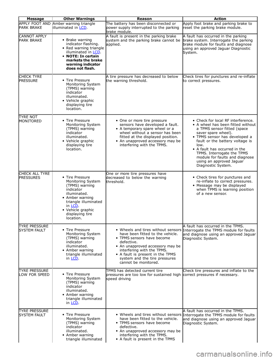
Message Other Warnings Reason Action APPLY FOOT AND
PARK BRAKE Amber warning triangle
illuminated in LCD. The battery has been disconnected or
power supply interrupted to the parking
brake module. Apply foot brake and parking brake to
reset the parking brake module. CANNOT APPLY
PARK BRAKE
Brake warning
indicator flashing.
Red warning triangle
illuminated in LCD. NOTE: In certain
markets the brake
warning indicator
does not flash. A fault is present in the parking brake
system and the parking brake cannot be
applied. A fault has occurred in the parking
brake system. Interrogate the parking
brake module for faults and diagnose
using an approved Jaguar Diagnostic
System. CHECK TYRE
PRESSURE
Tire Pressure
Monitoring System
(TPMS) warning
indicator
illuminated.
Vehicle graphic
displaying tire
location. A tire pressure has decreased to below
the warning threshold. Check tires for punctures and re-inflate
to correct pressures. TYRE NOT
MONITORED
Tire Pressure
Monitoring System
(TPMS) warning
indicator
illuminated.
Vehicle graphic
displaying tire
location.
One or more tire pressure
sensors have developed a fault.
A temporary spare wheel or a
wheel without a sensor has been
fitted at the displayed position.
An unapproved accessory may be
interfering with the TPMS.
Check for local RF interference.
A wheel has been fitted without
a TPMS sensor fitted (space
saver spare wheel).
TPMS sensor has developed a
fault or the battery voltage is
low.
A fault has occurred in the
TPMS. Interrogate the TPMS
module for faults and diagnose
using an approved Jaguar
Diagnostic System. CHECK ALL TYRE
PRESSURES
Tire Pressure
Monitoring System
(TPMS) warning
indicator
illuminated.
Amber warning
triangle illuminated
in LCD. Vehicle graphic
displaying tire
location. One or more tire pressures have
decreased to below the warning
threshold.
Check tires for punctures and
re-inflate to correct pressures.
Message may be displayed
when TPMS is learning position
of a new sensor. TYRE PRESSURE
SYSTEM FAULT
Tire Pressure
Monitoring System
(TPMS) warning
indicator
illuminated.
Amber warning
triangle illuminated
in LCD.
Wheels and tires without sensors
have been fitted to the vehicle.
TPMS sensors have become
defective.
An unapproved accessory may be
interfering with the TPMS.
A fault is present in the TPMS
system and the tire pressures
cannot be monitored. A fault has occurred in the TPMS.
Interrogate the TPMS module for faults
and diagnose using an approved Jaguar
Diagnostic System. TYRE PRESSURE
LOW FOR SPEED
Tire Pressure
Monitoring System
(TPMS) warning
indicator
illuminated.
Amber warning
triangle illuminated
in LCD. TPMS has detected current tire
pressures are too low for sustained high
speed driving Check tire pressures and inflate to the
correct pressures if necessary. TYRE PRESSURE
SYSTEM FAULT
Tire Pressure
Monitoring System
(TPMS) warning
indicator
illuminated.
Amber warning
triangle illuminated
Wheels and tires without sensors
have been fitted to the vehicle.
TPMS sensors have become
defective.
An unapproved accessory may be
interfering with the TPMS.
A fault is present in the TPMS A fault has occurred in the TPMS.
Interrogate the TPMS module for faults
and diagnose using an approved Jaguar
Diagnostic System.
Page 1825 of 3039
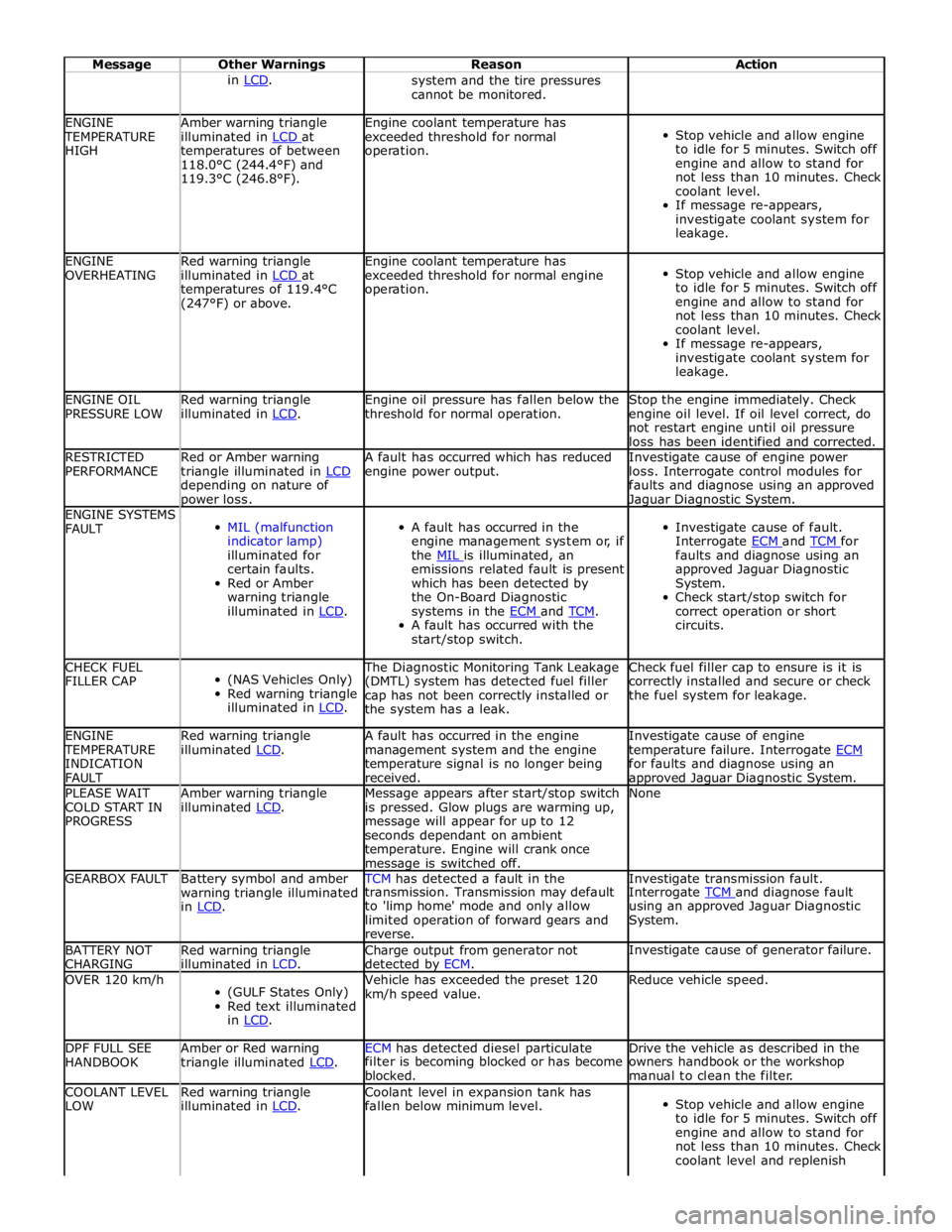
Message Other Warnings Reason Action in LCD. system and the tire pressures
cannot be monitored. ENGINE TEMPERATURE
HIGH Amber warning triangle
illuminated in LCD at temperatures of between
118.0°C (244.4°F) and
119.3°C (246.8°F). Engine coolant temperature has
exceeded threshold for normal
operation.
Stop vehicle and allow engine
to idle for 5 minutes. Switch off
engine and allow to stand for
not less than 10 minutes. Check
coolant level.
If message re-appears,
investigate coolant system for
leakage. ENGINE
OVERHEATING Red warning triangle
illuminated in LCD at temperatures of 119.4°C
(247°F) or above. Engine coolant temperature has
exceeded threshold for normal engine
operation.
Stop vehicle and allow engine
to idle for 5 minutes. Switch off
engine and allow to stand for
not less than 10 minutes. Check
coolant level.
If message re-appears,
investigate coolant system for
leakage. ENGINE OIL
PRESSURE LOW Red warning triangle
illuminated in LCD. Engine oil pressure has fallen below the
threshold for normal operation. Stop the engine immediately. Check
engine oil level. If oil level correct, do
not restart engine until oil pressure
loss has been identified and corrected. RESTRICTED
PERFORMANCE Red or Amber warning
triangle illuminated in LCD depending on nature of power loss. A fault has occurred which has reduced
engine power output. Investigate cause of engine power
loss. Interrogate control modules for
faults and diagnose using an approved Jaguar Diagnostic System. ENGINE SYSTEMS
FAULT
MIL (malfunction
indicator lamp)
illuminated for
certain faults.
Red or Amber
warning triangle
illuminated in LCD.
A fault has occurred in the
engine management system or, if
the MIL is illuminated, an emissions related fault is present
which has been detected by
the On-Board Diagnostic
systems in the ECM and TCM. A fault has occurred with the
start/stop switch.
Investigate cause of fault.
Interrogate ECM and TCM for faults and diagnose using an
approved Jaguar Diagnostic
System.
Check start/stop switch for
correct operation or short
circuits. CHECK FUEL
FILLER CAP
(NAS Vehicles Only)
Red warning triangle
illuminated in LCD. The Diagnostic Monitoring Tank Leakage
(DMTL) system has detected fuel filler
cap has not been correctly installed or
the system has a leak. Check fuel filler cap to ensure is it is
correctly installed and secure or check
the fuel system for leakage. ENGINE TEMPERATURE
INDICATION
FAULT Red warning triangle
illuminated LCD. A fault has occurred in the engine
management system and the engine
temperature signal is no longer being
received. Investigate cause of engine
temperature failure. Interrogate ECM for faults and diagnose using an approved Jaguar Diagnostic System. PLEASE WAIT
COLD START IN
PROGRESS Amber warning triangle
illuminated LCD. Message appears after start/stop switch
is pressed. Glow plugs are warming up,
message will appear for up to 12
seconds dependant on ambient
temperature. Engine will crank once message is switched off. None GEARBOX FAULT
Battery symbol and amber
warning triangle illuminated
in LCD. TCM has detected a fault in the Investigate transmission fault. transmission. Transmission may default
to 'limp home' mode and only allow
limited operation of forward gears and
reverse. Interrogate TCM and diagnose fault using an approved Jaguar Diagnostic
System. BATTERY NOT
CHARGING Red warning triangle
illuminated in LCD. Charge output from generator not
detected by ECM. Investigate cause of generator failure. OVER 120 km/h
(GULF States Only)
Red text illuminated
in LCD. Vehicle has exceeded the preset 120
km/h speed value. Reduce vehicle speed. DPF FULL SEE
HANDBOOK Amber or Red warning
triangle illuminated LCD. ECM has detected diesel particulate Drive the vehicle as described in the filter is becoming blocked or has become
blocked. owners handbook or the workshop
manual to clean the filter. COOLANT LEVEL
LOW Red warning triangle
illuminated in LCD. Coolant level in expansion tank has
fallen below minimum level.
Stop vehicle and allow engine
to idle for 5 minutes. Switch off
engine and allow to stand for
not less than 10 minutes. Check
coolant level and replenish
Page 1826 of 3039
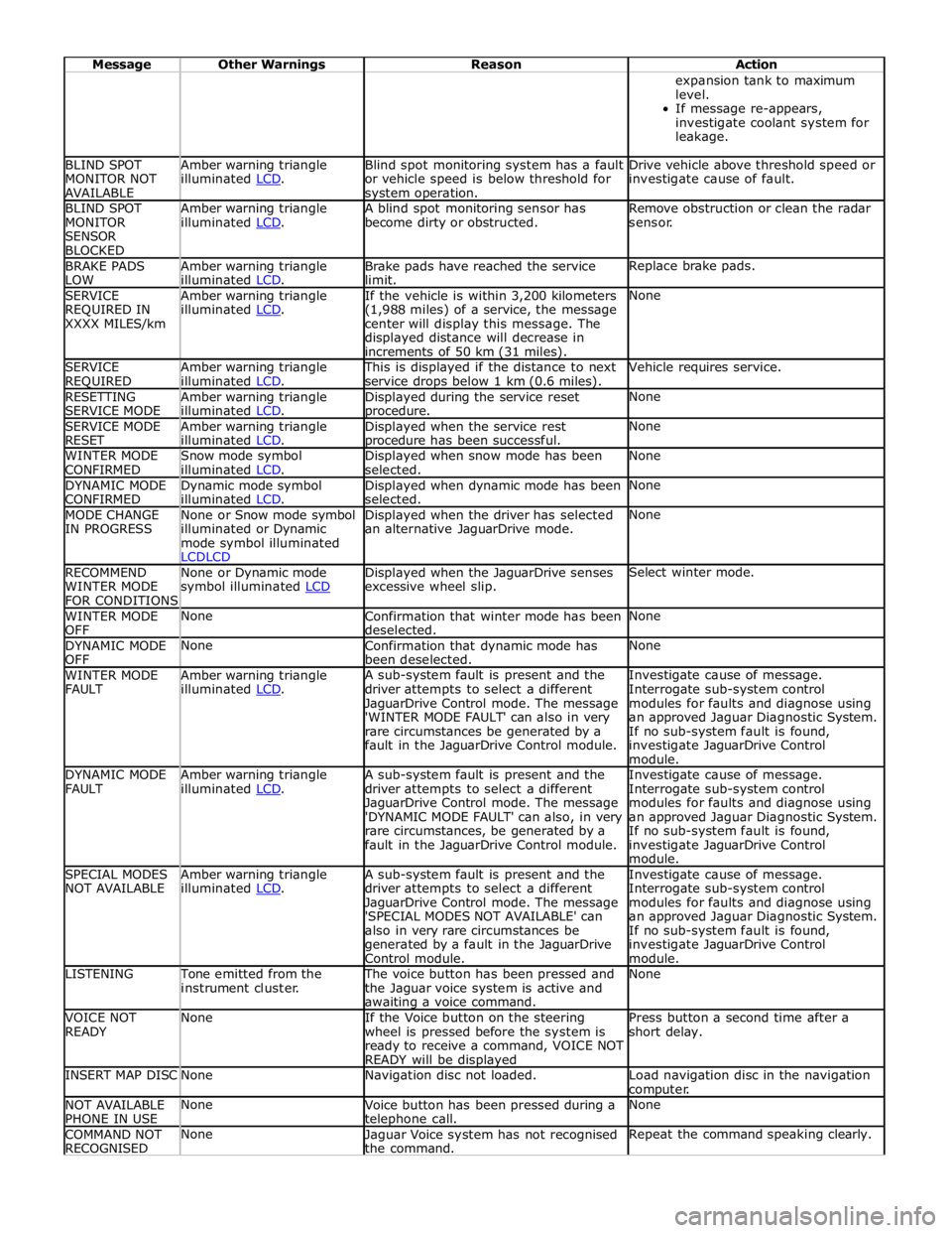
Message Other Warnings Reason Action expansion tank to maximum
level.
If message re-appears,
investigate coolant system for
leakage. BLIND SPOT
MONITOR NOT
AVAILABLE Amber warning triangle
illuminated LCD. Blind spot monitoring system has a fault
or vehicle speed is below threshold for system operation. Drive vehicle above threshold speed or
investigate cause of fault. BLIND SPOT
MONITOR
SENSOR
BLOCKED Amber warning triangle
illuminated LCD. A blind spot monitoring sensor has
become dirty or obstructed. Remove obstruction or clean the radar
sensor. BRAKE PADS
LOW Amber warning triangle
illuminated LCD. Brake pads have reached the service
limit. Replace brake pads. SERVICE
REQUIRED IN
XXXX MILES/km Amber warning triangle
illuminated LCD. If the vehicle is within 3,200 kilometers
(1,988 miles) of a service, the message
center will display this message. The
displayed distance will decrease in
increments of 50 km (31 miles). None SERVICE
REQUIRED Amber warning triangle
illuminated LCD. This is displayed if the distance to next
service drops below 1 km (0.6 miles). Vehicle requires service. RESETTING
SERVICE MODE Amber warning triangle
illuminated LCD. Displayed during the service reset procedure. None SERVICE MODE
RESET Amber warning triangle
illuminated LCD. Displayed when the service rest procedure has been successful. None WINTER MODE
CONFIRMED Snow mode symbol
illuminated LCD. Displayed when snow mode has been
selected. None DYNAMIC MODE
CONFIRMED Dynamic mode symbol
illuminated LCD. Displayed when dynamic mode has been
selected. None MODE CHANGE
IN PROGRESS None or Snow mode symbol
illuminated or Dynamic
mode symbol illuminated
LCDLCD Displayed when the driver has selected
an alternative JaguarDrive mode. None RECOMMEND
WINTER MODE
FOR CONDITIONS None or Dynamic mode
symbol illuminated LCD Displayed when the JaguarDrive senses
excessive wheel slip. Select winter mode. WINTER MODE
OFF None
Confirmation that winter mode has been
deselected. None DYNAMIC MODE
OFF None
Confirmation that dynamic mode has
been deselected. None WINTER MODE
FAULT Amber warning triangle
illuminated LCD. A sub-system fault is present and the
driver attempts to select a different
JaguarDrive Control mode. The message
'WINTER MODE FAULT' can also in very
rare circumstances be generated by a
fault in the JaguarDrive Control module. Investigate cause of message.
Interrogate sub-system control
modules for faults and diagnose using
an approved Jaguar Diagnostic System.
If no sub-system fault is found,
investigate JaguarDrive Control
module. DYNAMIC MODE
FAULT Amber warning triangle
illuminated LCD. A sub-system fault is present and the
driver attempts to select a different
JaguarDrive Control mode. The message
'DYNAMIC MODE FAULT' can also, in very
rare circumstances, be generated by a
fault in the JaguarDrive Control module. Investigate cause of message.
Interrogate sub-system control
modules for faults and diagnose using
an approved Jaguar Diagnostic System.
If no sub-system fault is found,
investigate JaguarDrive Control
module. SPECIAL MODES
NOT AVAILABLE Amber warning triangle
illuminated LCD. A sub-system fault is present and the
driver attempts to select a different
JaguarDrive Control mode. The message
'SPECIAL MODES NOT AVAILABLE' can
also in very rare circumstances be
generated by a fault in the JaguarDrive
Control module. Investigate cause of message.
Interrogate sub-system control
modules for faults and diagnose using
an approved Jaguar Diagnostic System.
If no sub-system fault is found,
investigate JaguarDrive Control
module. LISTENING Tone emitted from the
instrument cluster. The voice button has been pressed and
the Jaguar voice system is active and awaiting a voice command. None VOICE NOT
READY None
If the Voice button on the steering
wheel is pressed before the system is
ready to receive a command, VOICE NOT
READY will be displayed Press button a second time after a
short delay. INSERT MAP DISC None Navigation disc not loaded.
Load navigation disc in the navigation
computer. NOT AVAILABLE
PHONE IN USE None
Voice button has been pressed during a telephone call. None COMMAND NOT
RECOGNISED None
Jaguar Voice system has not recognised
the command. Repeat the command speaking clearly.
Page 1829 of 3039
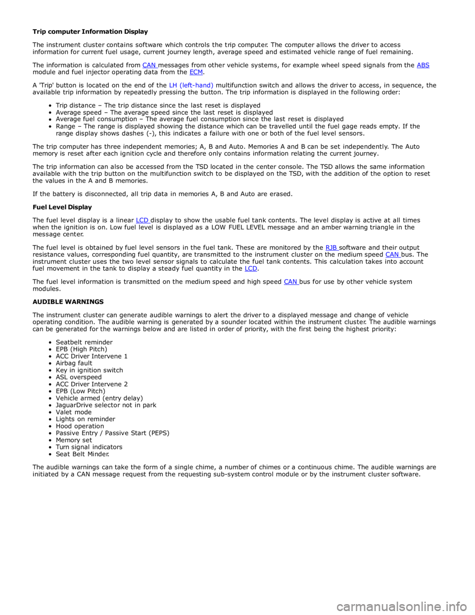
module and fuel injector operating data from the ECM.
A 'Trip' button is located on the end of the LH (left-hand) multifunction switch and allows the driver to access, in sequence, the
available trip information by repeatedly pressing the button. The trip information is displayed in the following order:
Trip distance – The trip distance since the last reset is displayed
Average speed – The average speed since the last reset is displayed
Average fuel consumption – The average fuel consumption since the last reset is displayed
Range – The range is displayed showing the distance which can be travelled until the fuel gage reads empty. If the
range display shows dashes (-), this indicates a failure with one or both of the fuel level sensors.
The trip computer has three independent memories; A, B and Auto. Memories A and B can be set independently. The Auto
memory is reset after each ignition cycle and therefore only contains information relating the current journey.
The trip information can also be accessed from the TSD located in the center console. The TSD allows the same information
available with the trip button on the multifunction switch to be displayed on the TSD, with the addition of the option to reset
the values in the A and B memories.
If the battery is disconnected, all trip data in memories A, B and Auto are erased.
Fuel Level Display
The fuel level display is a linear LCD display to show the usable fuel tank contents. The level display is active at all times when the ignition is on. Low fuel level is displayed as a LOW FUEL LEVEL message and an amber warning triangle in the
message center.
The fuel level is obtained by fuel level sensors in the fuel tank. These are monitored by the RJB software and their output resistance values, corresponding fuel quantity, are transmitted to the instrument cluster on the medium speed CAN bus. The instrument cluster uses the two level sensor signals to calculate the fuel tank contents. This calculation takes into account
fuel movement in the tank to display a steady fuel quantity in the LCD.
The fuel level information is transmitted on the medium speed and high speed CAN bus for use by other vehicle system modules.
AUDIBLE WARNINGS
The instrument cluster can generate audible warnings to alert the driver to a displayed message and change of vehicle
operating condition. The audible warning is generated by a sounder located within the instrument cluster. The audible warnings
can be generated for the warnings below and are listed in order of priority, with the first being the highest priority:
Seatbelt reminder
EPB (High Pitch)
ACC Driver Intervene 1
Airbag fault
Key in ignition switch
ASL overspeed
ACC Driver Intervene 2
EPB (Low Pitch)
Vehicle armed (entry delay)
JaguarDrive selector not in park
Valet mode
Lights on reminder
Hood operation
Passive Entry / Passive Start (PEPS)
Memory set
Turn signal indicators
Seat Belt Minder.
The audible warnings can take the form of a single chime, a number of chimes or a continuous chime. The audible warnings are
initiated by a CAN message request from the requesting sub-system control module or by the instrument cluster software.
Page 1869 of 3039
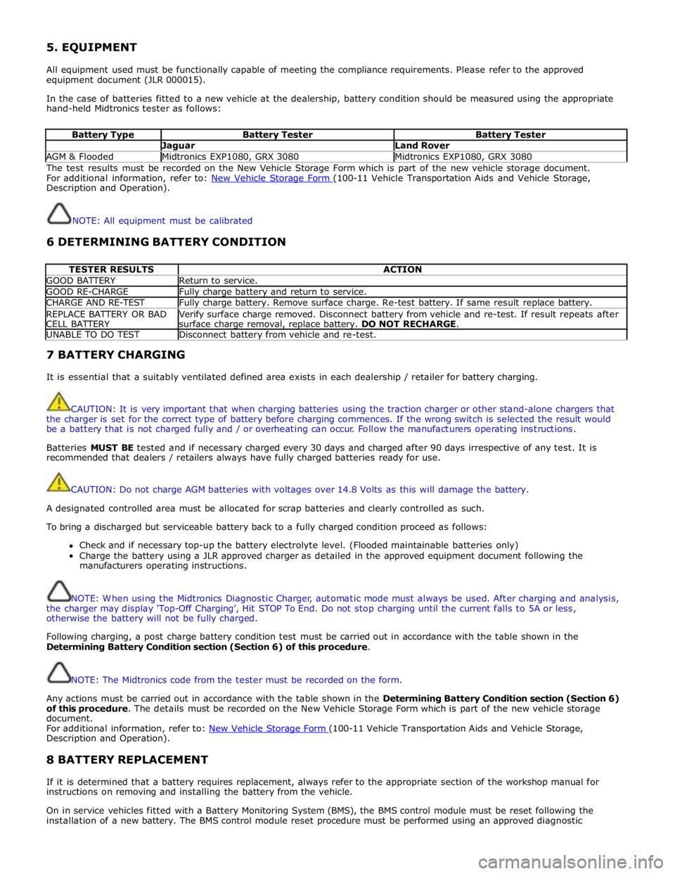
5. EQUIPMENT
All equipment used must be functionally capable of meeting the compliance requirements. Please refer to the approved
equipment document (JLR 000015).
In the case of batteries fitted to a new vehicle at the dealership, battery condition should be measured using the appropriate
hand-held Midtronics tester as follows:
Battery Type Battery Tester Battery Tester Jaguar Land Rover AGM & Flooded Midtronics EXP1080, GRX 3080 Midtronics EXP1080, GRX 3080 The test results must be recorded on the New Vehicle Storage Form which is part of the new vehicle storage document.
For additional information, refer to: New Vehicle Storage Form (100-11 Vehicle Transportation Aids and Vehicle Storage, Description and Operation).
NOTE: All equipment must be calibrated
6 DETERMINING BATTERY CONDITION
TESTER RESULTS ACTION GOOD BATTERY Return to service. GOOD RE-CHARGE Fully charge battery and return to service. CHARGE AND RE-TEST Fully charge battery. Remove surface charge. Re-test battery. If same result replace battery. REPLACE BATTERY OR BAD
CELL BATTERY Verify surface charge removed. Disconnect battery from vehicle and re-test. If result repeats after
surface charge removal, replace battery. DO NOT RECHARGE. UNABLE TO DO TEST Disconnect battery from vehicle and re-test. 7 BATTERY CHARGING
It is essential that a suitably ventilated defined area exists in each dealership / retailer for battery charging.
CAUTION: It is very important that when charging batteries using the traction charger or other stand-alone chargers that
the charger is set for the correct type of battery before charging commences. If the wrong switch is selected the result would
be a battery that is not charged fully and / or overheating can occur. Follow the manufacturers operating instructions.
Batteries MUST BE tested and if necessary charged every 30 days and charged after 90 days irrespective of any test. It is
recommended that dealers / retailers always have fully charged batteries ready for use.
CAUTION: Do not charge AGM batteries with voltages over 14.8 Volts as this will damage the battery.
A designated controlled area must be allocated for scrap batteries and clearly controlled as such.
To bring a discharged but serviceable battery back to a fully charged condition proceed as follows:
Check and if necessary top-up the battery electrolyte level. (Flooded maintainable batteries only)
Charge the battery using a JLR approved charger as detailed in the approved equipment document following the
manufacturers operating instructions.
NOTE: When using the Midtronics Diagnostic Charger, automatic mode must always be used. After charging and analysis,
the charger may display ‘Top-Off Charging’, Hit STOP To End. Do not stop charging until the current falls to 5A or less,
otherwise the battery will not be fully charged.
Following charging, a post charge battery condition test must be carried out in accordance with the table shown in the
Determining Battery Condition section (Section 6) of this procedure.
NOTE: The Midtronics code from the tester must be recorded on the form.
Any actions must be carried out in accordance with the table shown in the Determining Battery Condition section (Section 6)
of this procedure. The details must be recorded on the New Vehicle Storage Form which is part of the new vehicle storage
document.
For additional information, refer to: New Vehicle Storage Form (100-11 Vehicle Transportation Aids and Vehicle Storage, Description and Operation).
8 BATTERY REPLACEMENT
If it is determined that a battery requires replacement, always refer to the appropriate section of the workshop manual for
instructions on removing and installing the battery from the vehicle.
On in service vehicles fitted with a Battery Monitoring System (BMS), the BMS control module must be reset following the
installation of a new battery. The BMS control module reset procedure must be performed using an approved diagnostic
Page 1871 of 3039

Published: 21-Dec-2012
Battery and Charging System - General Information - Quiescent Drain
Description and Operation
VEHICLE QUIESCENT CURRENT TESTING
On vehicles fitted with a Battery Monitoring System (BMS), the diagnostic routine for quiescent drain testing in the approved
Jaguar or Land Rover diagnostic system should be utilized.
If a customer complains of a vehicle battery that discharges continuously or when left for a prolonged period of time, it is
recommended that a quiescent drain test is performed as described below.
The battery drain should be measured using the approved Jaguar or Land Rover diagnostic system or a Digital Multi-Meter
(DVOM). A procedure for quiescent drain measurement using the diagnostic system is available in the Diagnosis and Testing
section of the Workshop Manual. The vehicle should be in the locked/armed state (for example vehicle alarm fully armed), all
doors, engine and luggage compartment lids are open and latched (so as to appear closed from an electrical point of view).
The test should take place after the vehicle has entered shutdown mode. The time taken for this to occur after the ignition is
switched off varies according to model (Refer to the Topix On line resource for details).
When the vehicle is armed, the effect of the security system Light Emitting Diode (LED) flashing is to cause a pulsation in the
measured current drain. In this case, either the average current should be taken (using a Digital Multi- Meter (DVOM) with an
averaging system) or the current reading taken, ignoring the brief high current peaks.
EQUIPMENT
Approved Jaguar or Land Rover diagnostic system with current probeOR Digital Multi-Meter (DVOM) with current probe.
METHOD OF MEASUREMENT
Using an Approved Jaguar or Land Rover Diagnostic System.
1. Switch off all electrical loads and ensure that the ignition is off
2. Connect the current probe to the approved Jaguar or Land Rover diagnostic system
3. Calibrate the probe
4. Install a clamp around the battery lead/junction box lead
5. Go to the Quiescent Current Testing section in this procedure
Using a digital multimeter
Do not use an in-line DVOM to measure the quiescent drain on vehicles fitted with an electronic throttle (for example XK 2006
onwards). The current exceeds the maximum amount the fuse in the DVOM is capable of handling.
1. Switch off all electrical loads and ensure that the ignition is off
2. Connect the current probe to the digital multmeter
3. Calibrate the probe
4. Install a clamp around the battery lead/junction box lead
5. Go to the Quiescent Current Testing section in this procedure
QUIESCENT CURRENT TESTING
1. Switch ignition to ‘on’ or select ignition mode in keyless vehicles and switch to ‘off’ (do not crank)
2. Remove key from ignition switch (if equipped)
3. Open and latch all doors, hood and luggage compartment lid
4. Lock the vehicle using the remote function on the remote handset. (Single lock only to avoid volumetric alarm arming)
5. Remove any other potential electrical drains such as accessories plugged into accessory sockets
6. Record the amperage readings after the shutdown period referenced in the Topix on line resource for details. Note all
cars from 10MY onwards and XK from 07MY and XF from 08MY should be less than 30mA after 30 minutes
7. Record the final reading on the battery report form
The preferred method of testing following an excessive current consumption figure is to use a current probe around individual
junction box leads to the various suspected circuits to identify a potential cause. This is in preference to the old method of
removing fuses for the following reasons:
The drain may be caused by a module remaining active and preventing the quiescent drain from reducing to normal
levels
The drain may be caused by a relay winding that is activated. Pulling the fuse can allow this to ‘reset’ and the drain will
be lost and go un-diagnosed
QUIESCENT DRAIN - TYPICAL VALUES
NOTE: The quiescent drain after the initial shutdown period should not exceed the value shown in the table.
Jaguar Quiescent Drain Values
MODEL SHUT DOWN PERIOD (minutes) TYPICAL VALUES BATTERY DRAIN (mA) XJS 3.2 60 <30 Sovereign 3.2 60 <37.3