2010 JAGUAR XFR reset
[x] Cancel search: resetPage 648 of 3039

7 Instrument cluster 8 Parking brake switch 9 Parking brake actuator
Static Apply System Operation
The EPB module receives a vehicle speed signal from the ABS (anti-lock brake system) module on the high speed CAN bus. If the parking brake switch is pulled to the 'Apply' position and vehicle speed is less than 2 mph (3 km/h), the EPB module will
instigate its 'Static Apply' mode and drive the actuator to apply full parking brake force to the rear wheels.
The EPB module monitors the current drawn by the actuator and compares this to information held within its configuration
software to determine when full braking force has been applied.
Dynamic Apply
There are two 'Dynamic Apply' modes; low speed dynamic and high speed dynamic. The low speed dynamic mode operates at
speeds between 2 mph (3 km/h) and 20 mph (32 km/h). The high speed dynamic mode operates at speeds above 20 mph (32
km/h).
If the parking brake switch is pulled up to the 'Apply' position and vehicle speed is within the low speed dynamic range, the
EPB module drives the actuator to apply full parking brake force to the rear wheels.
If the parking brake switch is pulled up to the 'Apply' position and vehicle speed is within the high speed dynamic range, the
EPB module will apply braking force to the rear wheels at a slower rate until full braking load is reached or the switch is
released. The rate with which braking force is applied is controlled by the EPB module, which monitors both current drawn by
the actuator and positional information from the actuator hall sensor and compares this to information held within its
configuration software.
Drive Away Release
The EPB module will initiate its 'Drive Away Release' function and automatically release the parking brake if the following
conditions are detected:
The engine is running.
Drive , or reverse is selected.
Positive throttle movement is detected.
The EPB module receives messages of gear selector position and throttle angle over the high speed CAN bus from the TCM (transmission control module) and the ECM (engine control module) respectively.
Release from Park
The EPB module will initiate its 'Release from Park' function and automatically release the parking brake if the gear selector is
moved from Park to any position except Neutral.
Repairs
Before carrying out any work on the parking brake system, the Jaguar approved diagnostic system must be connected and the
'parking brake unjam' routine run. The routine can be found in the 'Vehicle Configuration' area, under the 'Set-up and
Configuration' menu. After any work has been carried out on the parking brake, the system will require resetting.
CAUTION: Do not use the 'Emergency Release' tool to allow work to be carried out on the parking brake. Work can only be
carried out on the parking brake system after the 'parking brake unjam' routine has been run.
Resetting
If the electrical supply is disconnected from the EPB module, the actuator will loose its position memory. On battery
re-connection and ignition on, 'APPLY FOOT AND PARK BRAKE' will be displayed in the instrument cluster message center
indicating the parking brake requires resetting.
Refer to: Parking Brake (206-05, Diagnosis and Testing).
Operating Voltages
The EPB module will only operate the actuator if the power supply from the battery is between 9 V and 16 V. At any voltage
within this range, the actuator is able to fully tighten and release the brake cables. If the power supply falls outside of the
range, a fault code is stored in the EPB module and can be retrieved using the Jaguar approved diagnostic system.
Page 797 of 3039

Published: 11-May-2011
Steering Column Switches - Steering Column Switches - Overview
Description and Operation
OVERVIEW
The steering column multifunction switch is situated on the steering column and consists of the wiper switch, the turn signal
indicator/lighting switch and the trip computer switch.
The RH (right-hand) multifunction switch controls the following windshield wiper functions:
Flick wipe
Intermittent wipe
Slow speed wipe
High speed wipe
Wash/Wipe
Headlamp powerwash
Rain sensing / variable wipe selection.
The LH (left-hand) multifunction switch controls the following functions:
Turn signal indicators
Side lamps
Headlamps
Auto lamps
High/low beam
Headlamp flash
Headlamp timer
Trip computer.
The steering column adjustment switch is located in the steering column lower shroud on the LH side. The switch is a 4 position 'joystick' which controls reach and rake adjustment.
The trip button allows the driver to cycle though an option menu and also reset trip cycle mileage calculations. The trip
computer information is displayed in the instrument cluster message centre.
Steering wheel mounted switches on the LH side of the driver's airbag, control the audio and telephone functions. Switches on the RH side of the driver's airbag, control the speed control functions. The steering wheel has an internal heating element. This is controlled by the driver via the Touch Screen Display (TSD). www.JagDocs.com
Page 803 of 3039

automatically reset once the applicable remote handset has been detected by the vehicle security systems.
STEERING WHEEL HEATER
On certain models the rim of the steering wheel contains a heater element. Operation of the heater is selected using the
Touch Screen Display (TSD).
The heater temperature is controlled by a heated steering wheel control module located within the steering wheel. Power for
the heater element is supplied to the steering wheel via 2 contacts on the clockspring and a slip ring mounted on the steering
wheel.
Page 1360 of 3039
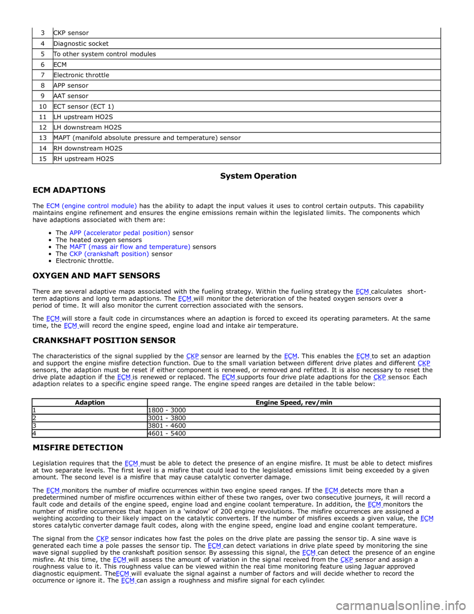
4 Diagnostic socket 5 To other system control modules 6 ECM 7 Electronic throttle 8 APP sensor 9 AAT sensor 10 ECT sensor (ECT 1) 11 LH upstream HO2S 12 LH downstream HO2S 13 MAPT (manifold absolute pressure and temperature) sensor 14 RH downstream HO2S 15 RH upstream HO2S
ECM ADAPTIONS System Operation
The ECM (engine control module) has the ability to adapt the input values it uses to control certain outputs. This capability
maintains engine refinement and ensures the engine emissions remain within the legislated limits. The components which
have adaptions associated with them are:
The APP (accelerator pedal position) sensor
The heated oxygen sensors
The MAFT (mass air flow and temperature) sensors
The CKP (crankshaft position) sensor
Electronic throttle.
OXYGEN AND MAFT SENSORS
There are several adaptive maps associated with the fueling strategy. Within the fueling strategy the ECM calculates short-term adaptions and long term adaptions. The ECM will monitor the deterioration of the heated oxygen sensors over a period of time. It will also monitor the current correction associated with the sensors.
The ECM will store a fault code in circumstances where an adaption is forced to exceed its operating parameters. At the same time, the ECM will record the engine speed, engine load and intake air temperature.
CRANKSHAFT POSITION SENSOR
The characteristics of the signal supplied by the CKP sensor are learned by the ECM. This enables the ECM to set an adaption and support the engine misfire detection function. Due to the small variation between different drive plates and different CKP sensors, the adaption must be reset if either component is renewed, or removed and refitted. It is also necessary to reset the
drive plate adaption if the ECM is renewed or replaced. The ECM supports four drive plate adaptions for the CKP sensor. Each adaption relates to a specific engine speed range. The engine speed ranges are detailed in the table below:
Adaption Engine Speed, rev/min 1 1800 - 3000 2 3001 - 3800 3 3801 - 4600 4 4601 - 5400 MISFIRE DETECTION
Legislation requires that the ECM must be able to detect the presence of an engine misfire. It must be able to detect misfires at two separate levels. The first level is a misfire that could lead to the legislated emissions limit being exceeded by a given
amount. The second level is a misfire that may cause catalytic converter damage.
The ECM monitors the number of misfire occurrences within two engine speed ranges. If the ECM detects more than a predetermined number of misfire occurrences within either of these two ranges, over two consecutive journeys, it will record a
fault code and details of the engine speed, engine load and engine coolant temperature. In addition, the ECM monitors the number of misfire occurrences that happen in a 'window' of 200 engine revolutions. The misfire occurrences are assigned a
weighting according to their likely impact on the catalytic converters. If the number of misfires exceeds a given value, the ECM stores catalytic converter damage fault codes, along with the engine speed, engine load and engine coolant temperature.
The signal from the CKP sensor indicates how fast the poles on the drive plate are passing the sensor tip. A sine wave is generated each time a pole passes the sensor tip. The ECM can detect variations in drive plate speed by monitoring the sine wave signal supplied by the crankshaft position sensor. By assessing this signal, the ECM can detect the presence of an engine misfire. At this time, the ECM will assess the amount of variation in the signal received from the CKP sensor and assign a roughness value to it. This roughness value can be viewed within the real time monitoring feature using Jaguar approved
diagnostic equipment. TheECM will evaluate the signal against a number of factors and will decide whether to record the occurrence or ignore it. The ECM can assign a roughness and misfire signal for each cylinder.
Page 1531 of 3039
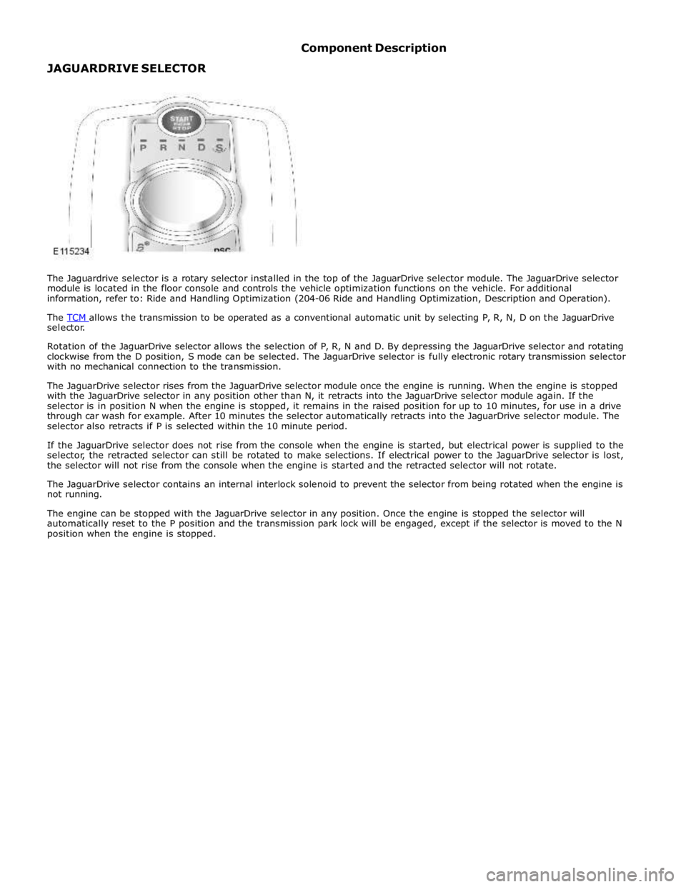
selector.
Rotation of the JaguarDrive selector allows the selection of P, R, N and D. By depressing the JaguarDrive selector and rotating
clockwise from the D position, S mode can be selected. The JaguarDrive selector is fully electronic rotary transmission selector
with no mechanical connection to the transmission.
The JaguarDrive selector rises from the JaguarDrive selector module once the engine is running. When the engine is stopped
with the JaguarDrive selector in any position other than N, it retracts into the JaguarDrive selector module again. If the
selector is in position N when the engine is stopped, it remains in the raised position for up to 10 minutes, for use in a drive
through car wash for example. After 10 minutes the selector automatically retracts into the JaguarDrive selector module. The
selector also retracts if P is selected within the 10 minute period.
If the JaguarDrive selector does not rise from the console when the engine is started, but electrical power is supplied to the
selector, the retracted selector can still be rotated to make selections. If electrical power to the JaguarDrive selector is lost,
the selector will not rise from the console when the engine is started and the retracted selector will not rotate.
The JaguarDrive selector contains an internal interlock solenoid to prevent the selector from being rotated when the engine is
not running.
The engine can be stopped with the JaguarDrive selector in any position. Once the engine is stopped the selector will
automatically reset to the P position and the transmission park lock will be engaged, except if the selector is moved to the N
position when the engine is stopped.
Page 1722 of 3039
Climate Control - Center Registers
Removal and Installation
Removal Published: 11-May-2011
CAUTION: Do not manually open the registers. Failure to follow this instruction may result in damage to the internal
components.
NOTES:
The center registers must be open before carrying out this procedure. To achieve this set the registers to 'Always Open'
using the climate settings tab on the information and entertainment display. If the registers are set to 'Automatic' mode
(rotating with ignition on/off) and one or more are disconnected during an ignition cycle, a vehicle battery reset may be
required to reconnect the affected registers to the LIN BUS.
Removal steps in this procedure may contain installation details.
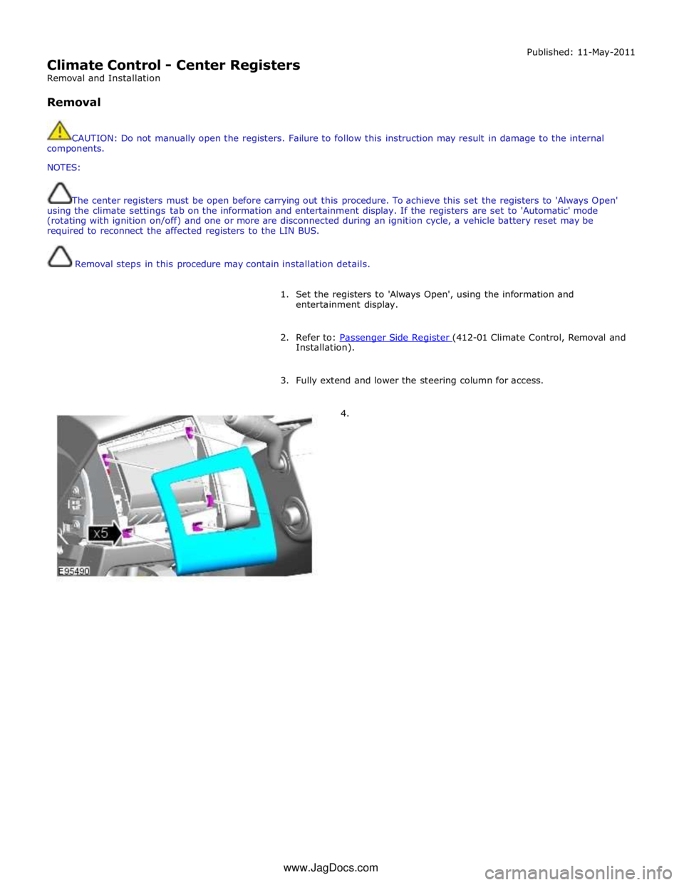
1. Set the registers to 'Always Open', using the information and
entertainment display.
2. Refer to: Passenger Side Register (412-01 Climate Control, Removal and Installation).
3. Fully extend and lower the steering column for access.
4. www.JagDocs.com
Page 1729 of 3039
Climate Control - Driver Side Register
Removal and Installation
Removal Published: 11-May-2011
CAUTION: Do not manually open the registers. Failure to follow this instruction may result in damage to the internal
components.
NOTES:
If the registers are set to 'Automatic' mode and one or more are disconnected during an ignition cycle, a vehicle battery
reset may be required to reconnect the affected registers to the LIN BUS.
Removal steps in this procedure may contain installation details.
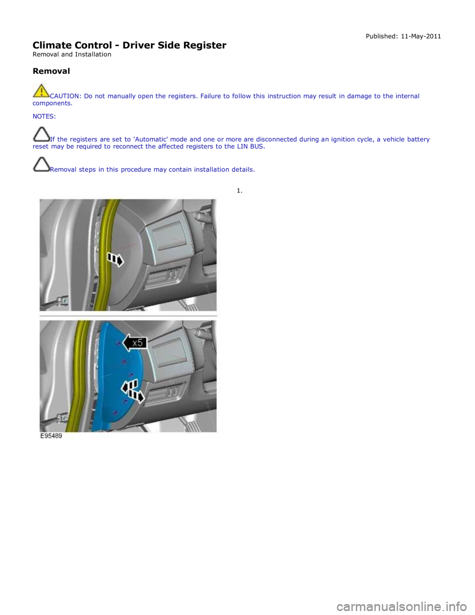
1.
Page 1751 of 3039
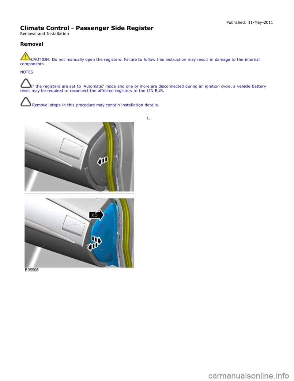
Climate Control - Passenger Side Register
Removal and Installation
Removal Published: 11-May-2011
CAUTION: Do not manually open the registers. Failure to follow this instruction may result in damage to the internal
components.
NOTES:
If the registers are set to 'Automatic' mode and one or more are disconnected during an ignition cycle, a vehicle battery
reset may be required to reconnect the affected registers to the LIN BUS.
Removal steps in this procedure may contain installation details.
1.