Page 463 of 3039

No
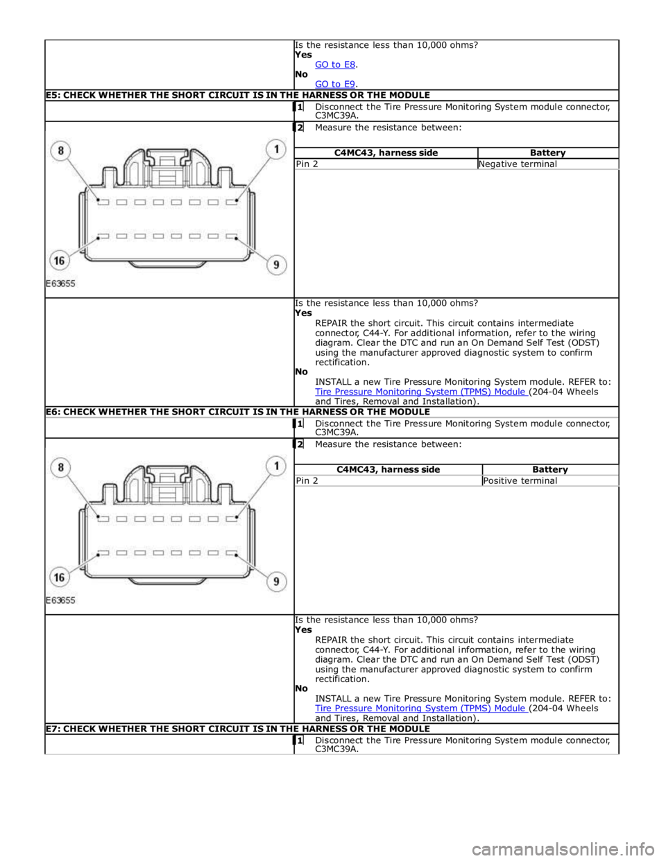
GO to E9. E5: CHECK WHETHER THE SHORT CIRCUIT IS IN THE HARNESS OR THE MODULE 1 Disconnect the Tire Pressure Monitoring System module connector, C3MC39A.
2 Measure the resistance between: C4MC43, harness side Battery Pin 2 Negative terminal Is the resistance less than 10,000 ohms?
Yes
REPAIR the short circuit. This circuit contains intermediate
connector, C44-Y. For additional information, refer to the wiring
diagram. Clear the DTC and run an On Demand Self Test (ODST)
using the manufacturer approved diagnostic system to confirm
rectification.
No
INSTALL a new Tire Pressure Monitoring System module. REFER to:
Tire Pressure Monitoring System (TPMS) Module (204-04 Wheels and Tires, Removal and Installation). E6: CHECK WHETHER THE SHORT CIRCUIT IS IN THE HARNESS OR THE MODULE 1 Disconnect the Tire Pressure Monitoring System module connector, C3MC39A.
2 Measure the resistance between: C4MC43, harness side Battery Pin 2 Positive terminal Is the resistance less than 10,000 ohms?
Yes
REPAIR the short circuit. This circuit contains intermediate
connector, C44-Y. For additional information, refer to the wiring
diagram. Clear the DTC and run an On Demand Self Test (ODST)
using the manufacturer approved diagnostic system to confirm
rectification.
No
INSTALL a new Tire Pressure Monitoring System module. REFER to:
Tire Pressure Monitoring System (TPMS) Module (204-04 Wheels and Tires, Removal and Installation). E7: CHECK WHETHER THE SHORT CIRCUIT IS IN THE HARNESS OR THE MODULE 1 Disconnect the Tire Pressure Monitoring System module connector, C3MC39A.
Page 464 of 3039

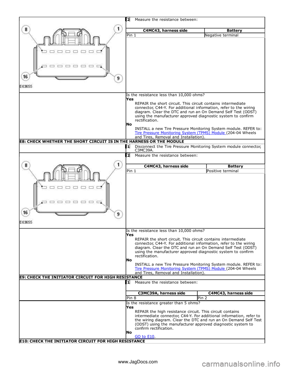
Measure the resistance between: C4MC43, harness side Battery Pin 1 Negative terminal Is the resistance less than 10,000 ohms?
Yes
REPAIR the short circuit. This circuit contains intermediate
connector, C44-Y. For additional information, refer to the wiring
diagram. Clear the DTC and run an On Demand Self Test (ODST)
using the manufacturer approved diagnostic system to confirm
rectification.
No
INSTALL a new Tire Pressure Monitoring System module. REFER to:
Tire Pressure Monitoring System (TPMS) Module (204-04 Wheels and Tires, Removal and Installation). E8: CHECK WHETHER THE SHORT CIRCUIT IS IN THE HARNESS OR THE MODULE 1 Disconnect the Tire Pressure Monitoring System module connector, C3MC39A.
2 Measure the resistance between: C4MC43, harness side Battery Pin 1 Positive terminal Is the resistance less than 10,000 ohms?
Yes
REPAIR the short circuit. This circuit contains intermediate
connector, C44-Y. For additional information, refer to the wiring
diagram. Clear the DTC and run an On Demand Self Test (ODST)
using the manufacturer approved diagnostic system to confirm
rectification.
No
INSTALL a new Tire Pressure Monitoring System module. REFER to:
Tire Pressure Monitoring System (TPMS) Module (204-04 Wheels and Tires, Removal and Installation). E9: CHECK THE INITIATOR CIRCUIT FOR HIGH RESISTANCE 1 Measure the resistance between: C3MC39A, harness side C4MC43, harness side Pin 8 Pin 2 Is the resistance greater than 5 ohms?
Yes
REPAIR the high resistance circuit. This circuit contains
intermediate connector, C44-Y. For additional information, refer to
the wiring diagram. Clear the DTC and run an On Demand Self Test
(ODST) using the manufacturer approved diagnostic system to
confirm rectification.
No
GO to E10. E10: CHECK THE INITIATOR CIRCUIT FOR HIGH RESISTANCE www.JagDocs.com
Page 465 of 3039

Measure the resistance between: C3MC39A, harness side C4MC43, harness side Pin 7 Pin 1 Is the resistance greater than 5 ohms?
Yes
REPAIR the high resistance circuit. This circuit contains
intermediate connector, C44-Y. For additional information, refer to
the wiring diagram. Clear the DTC and run an On Demand Self Test
(ODST) using the manufacturer approved diagnostic system to
confirm rectification.
No
INSTALL a new rear right hand low-frequency initiator. REFER to:
Tire Pressure Monitoring System (TPMS) Rear Antenna (204-04 Wheels and Tires, Removal and Installation).
PINPOINT TEST F : MISSING, INCOMPATIBLE OR DEFECTIVE RUNNING TIRE LOW PRESSURE SENSOR
OR RECEIVER TEST
CONDITIONS DETAILS/RESULTS/ACTIONS F1: CHECK FOR CORRECT WHEEL AND TIRE ASSEMBLY AND TIRE LOW PRESSURE SENSOR 1 Establish that a full size running wheel and tire assembly has a tire low pressure sensor installed. As a visual confirmation, a tire low pressure sensor has a metal valve stem rather than a rubber one and
cannot be installed to a mini/space saver spare wheel. Is a full size wheel and tire assembly with tire low pressure sensor installed?
Yes
GO to F2. No
Install the correct wheel and tire assembly or tire low pressure sensor, of correct frequency, in accordance
with that defined in the manufacturer approved diagnostic system new tire low pressure sensor
application. F2: CHECK FOR ADDITIONAL DTCS 1 Remove the Tire Pressure Monitoring System power supply fuse and re-install it. Clear DTCs and leave the vehicle stationary for 15 minutes, then drive it at a speed greater than 15.5 mph (25 kph)
continuously for at least 10 minutes.
(Note: If the vehicle speed drops below this value, the drive time to complete the test will need to be increased.)
The use of the manufacturer approved diagnostic system, and the datalogger signal ’Tire pressure
monitor system status – learn mode status’ will verify the completion of the test when the value returns
to ‘Inactive’. 2 Check for additional DTCs C1A5631, C1A5831, C1A6031, C1A6231, with identical time stamps. Have all four DTCs logged with identical time stamps in the tire pressure monitoring system module?
Yes
Replace the tire pressure monitoring system radio frequency receiver.
REFER to: Tire Pressure Monitoring System (TPMS) Receiver (204-04 Wheels and Tires, Removal and Installation).
No
GO to F3. F3: VERIFY THE POSITION OF THE DEFECTIVE TIRE LOW PRESSURE SENSOR 1 Check tire pressure monitoring system DTCs. Are any C1AXX31 DTCs logged?
Yes
Install the correct tire low pressure sensor, of correct frequency, in accordance with that defined in the
manufacturer approved diagnostic system new tire low pressure sensor application, to the position
identified by the logged DTC.
REFER to: Tire Low Pressure Sensor (204-04 Wheels and Tires, Removal and Installation). No
No further action is required.
(Note: The use of the manufacturer approved diagnostic system, and the datalogger signal ’Tire pressure monitor system status – learn completed successfully’ will verify the successful completion of the test.)
PINPOINT TEST G : LOCALIZATION FAILURE TEST
CONDITIONS DETAILS/RESULTS/ACTIONS G1: CHECK FOR ADDITIONAL DTCS 1 Check for additional DTCs: C1A5711, C1A5712, C1A5713. C1A5911, C1A5912, C1A5913, C1A6111, C1A6112, C1A6113, C1A6311, C1A6312, C1A6313. Are any of the DTCs listed above also logged?
Yes
Refer to the DTC Index and remedial actions.
No
GO to G2. G2: CHECK FOR ADDITIONAL DTCS
Page 482 of 3039
Published: 11-May-2011
Vehicle Dynamic Suspension - Vehicle Dynamic Suspension V8 5.0L Petrol/V8 S/C 5.0L Petrol - System Operation and Component Description
Description and Operation
Control Diagram
NOTE: A = Hardwired; D = High speed CAN (controller area network) bus
Item Description 1 Battery 2 BJB (battery junction box) (Megafuse (250 A) 3 AJB (auxiliary junction box) 4 CJB (central junction box) 5 ATC (automatic temperature control) module 6 Fuse 36 (10 A) - from delayed power-off relay
Page 531 of 3039
Published: 11-May-2011
Rear Drive Axle/Differential - Rear Drive Axle and Differential - System
Operation and Component Description
Description and Operation
Control Diagram
NOTE: A = Hardwired; D = High speed CAN (controller area network) bus
Control Diagram - 5.0L Supercharger Vehicles Only
Item Description 1 Battery 2 Megafuse (175 A) 3 AJB (auxiliary junction box) 4 Motor
Page 609 of 3039
Published: 11-May-2011
Front Disc Brake - TDV6 3.0L Diesel /V8 5.0L Petrol/V8 S/C 5.0L Petrol - Front Disc Brake - System Operation and Component Description
Description and Operation
Control Diagram
NOTE: A = Hardwired
Item Description 1 Battery 2 Megafuse (250 A) 3 Front brake pad wear sensor 4 Rear brake pad wear sensor 5 Instrument cluster 6 CJB (central junction box) 7 Power distribution box
Page 631 of 3039
Published: 11-May-2011
Rear Disc Brake - TDV6 3.0L Diesel /V8 5.0L Petrol/V8 S/C 5.0L Petrol - Rear
Disc Brake - System Operation and Component Description
Description and Operation
Control Diagram
NOTE: A = Hardwired
Item Description 1 Battery 2 Megafuse (250 A) 3 Front brake pad wear sensor 4 Rear brake pad wear sensor 5 Instrument cluster 6 CJB (central junction box) 7Powerdistributionbox
Page 647 of 3039
Published: 11-May-2011
Parking Brake and Actuation - Parking Brake - System Operation and
Component Description
Description and Operation
Control Diagram
NOTE: A = Hardwired; D = High speed CAN (controller area network) bus.
Item Description 1 Battery 2 BJB (battery junction box) 3 CJB (central junction box) 4 RJB (rear junction box) 5 EPB module 6 Stoplamp switch