2010 JAGUAR XFR diagram
[x] Cancel search: diagramPage 2563 of 3039
Roof Opening Panel - Roof Opening Panel
Diagnosis and Testing
Principle of Operation Published: 11-May-2011
For a detailed description of the roof opening panel, refer to the relevant Description and Operation sections in the workshop
manual. REFER to: (501-17 Roof Opening Panel)
Roof Opening Panel (Description and Operation), Roof Opening Panel (Description and Operation), Roof Opening Panel (Description and Operation).
Inspection and Verification
CAUTION: Diagnosis by substitution from a donor vehicle is NOT acceptable. Substitution of control modules does not
guarantee confirmation of a fault, and may also cause additional faults in the vehicle being tested and/or the donor vehicle.
1. Verify the customer concern.
2. Visually inspect for obvious signs of damage and system integrity.
Visual Inspection
Mechanical Electrical
Roof opening panel
Helixed drive cables
Switch
Control unit/motor
Fuses/relays (refer to electrical guide)
Wiring harness
Correct engagement of electrical connectors
Loose or corroded connections
3. If an obvious cause for an observed or reported concern is found, correct the cause (if possible) before proceeding to
the next step.
4. If the cause is not visually evident, check for Diagnostic Trouble Codes (DTCs) and refer to the DTC Index.
DTC Index
CAUTION: When probing connectors to take measurements in the course of the pinpoint tests, use the adaptor kit, part
number 3548-1358-00.
NOTES:
If the control module or a component is suspect and the vehicle remains under manufacturer warranty, refer to the
Warranty Policy and Procedures manual (section B1.2), or determine if any prior approval programme is in operation, prior to
the installation of a new module/component.
Generic scan tools may not read the codes listed, or may read only five digit codes. Match the five digits from the scan
tool to the first five digits of the seven digit code listed to identify the fault (the last two digits give extra information read by
the manufacturer-approved diagnostic system).
When performing voltage or resistance tests, always use a digital multimeter (DMM) accurate to three decimal places and
with a current calibration certificate. When testing resistance, always take the resistance of the DMM leads into account.
Check and rectify basic faults before beginning diagnostic routines involving pinpoint tests.
If DTCs are recorded and, after performing the pinpoint tests, a fault is not present, an intermittent concern may be the
cause. Always check for loose connections and corroded terminals.
DTC Description Possible Cause Action B10F211 Sunroof Control
Sunroof enable signal
circuit - short to ground Carry out any pinpoint tests associated with this DTC using the
manufacturer approved diagnostic system. Refer to the electrical
circuit diagrams and check sunroof enable signal circuit for short
to ground B10F212 Sunroof Control
Sunroof enable signal
circuit - short to power Refer to the electrical circuit diagrams and check sunroof enable
signal circuit for short to power
Page 2564 of 3039

DTC Description Possible Cause Action B10F213 Sunroof Control
Sunroof enable signal
circuit - open circuit Refer to the electrical circuit diagrams and check sunroof enable
signal circuit for open circuit B113D12
Sunroof Global
Open/Close
Control
Roof opening panel global
open/close control circuit -
short to power Carry out any pinpoint tests associated with this DTC using the
manufacturer approved diagnostic system. Refer to the electrical
circuit diagrams and check roof opening panel global open/close
control circuit for short to power B113D14
Sunroof Global
Open/Close
Control
Roof opening panel global
open/close control circuit -
short to ground, open
circuit Refer to the electrical circuit diagrams and check roof opening
panel global open/close control circuit for short to ground, open
circuit www.JagDocs.com
Page 2612 of 3039
Published: 26-Jun-2012
Supplemental Restraint System - Air Bag and Safety Belt Pretensioner
Supplemental Restraint System (SRS) - System Operation and Component Description
Description and Operation
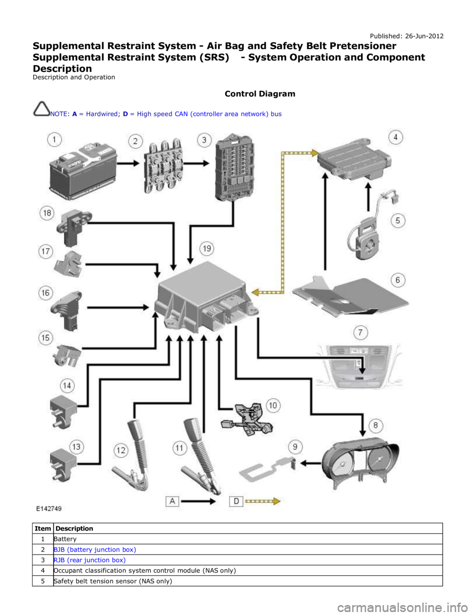
Control Diagram
NOTE: A = Hardwired; D = High speed CAN (controller area network) bus
Item Description 1 Battery 2 BJB (battery junction box) 3 RJB (rear junction box) 4 Occupant classification system control module (NAS only) 5 Safety belt tension sensor (NAS only)
Page 2683 of 3039
Published: 11-May-2011
Pedestrian Protection System - Pedestrian Protection System - System
Operation and Component Description
Description and Operation
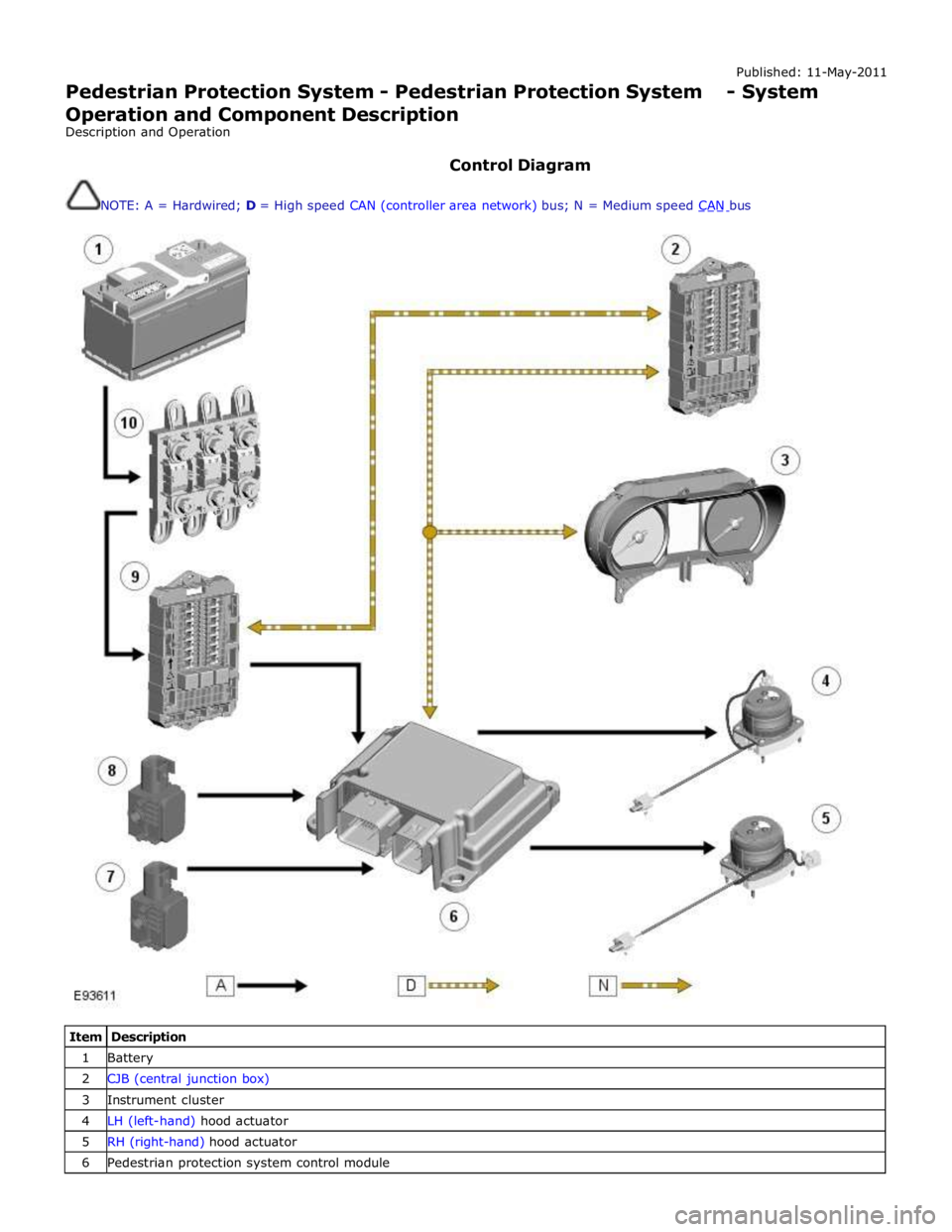
Control Diagram
NOTE: A = Hardwired; D = High speed CAN (controller area network) bus; N = Medium speed CAN bus
Item Description 1 Battery 2 CJB (central junction box) 3 Instrument cluster 4 LH (left-hand) hood actuator 5 RH (right-hand) hood actuator 6 Pedestrian protection system control module
Page 2707 of 3039
For instance, the crumple zones absorb the bulk of the impact energy. If any unprofessional repair techniques or
methods are used in these areas then this can pose a fundamental threat to vehicle safety.
Hidden damage
As well as looking at external indicators like flaked off paint, it is vital to check for hidden body damage or deformation
that is not visible from the outside. Large attached parts like bumpers and inner fenders often need to be removed to
allow accurate assessment of damage to underlying body parts.
Gap dimensions
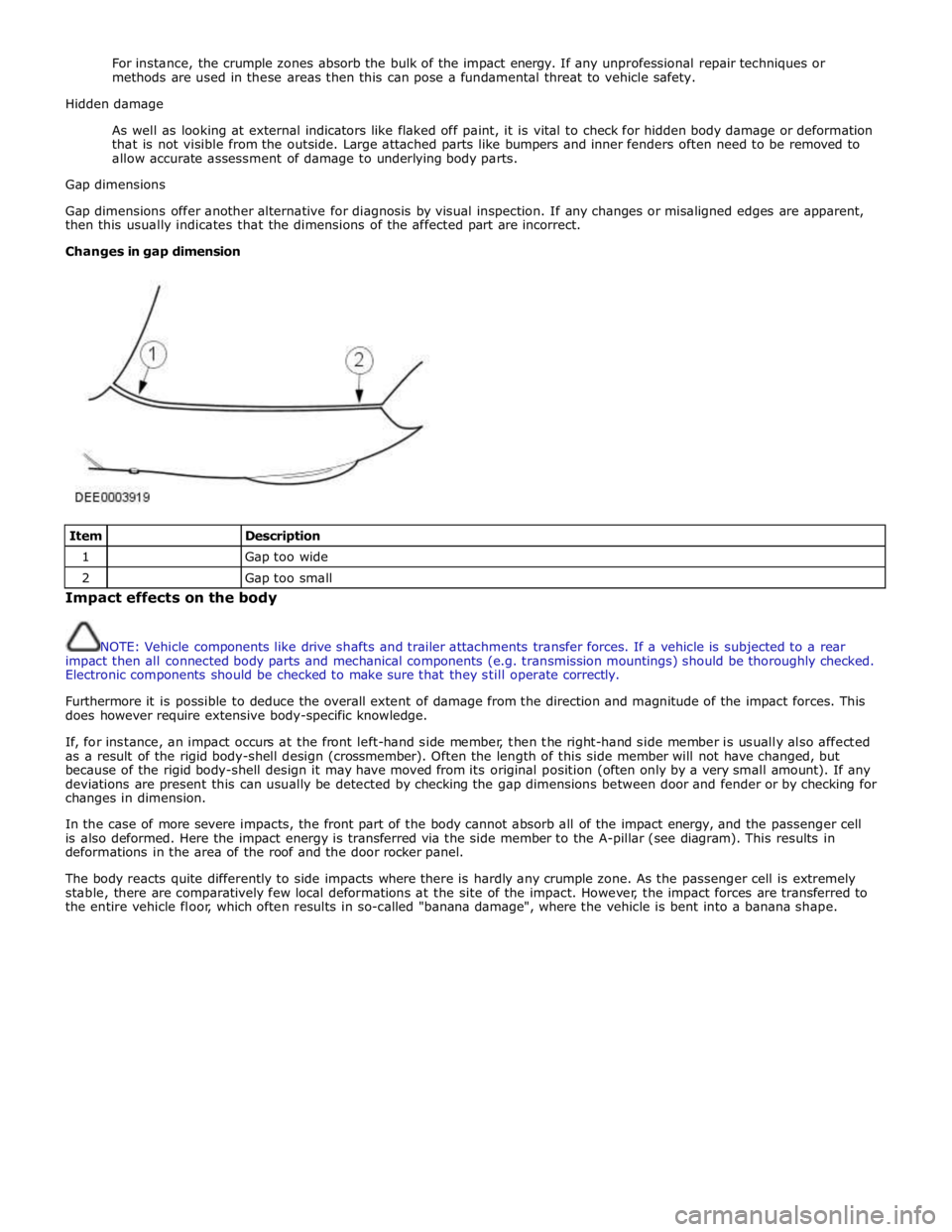
Gap dimensions offer another alternative for diagnosis by visual inspection. If any changes or misaligned edges are apparent,
then this usually indicates that the dimensions of the affected part are incorrect.
Changes in gap dimension
Item
Description 1
Gap too wide 2
Gap too small Impact effects on the body
NOTE: Vehicle components like drive shafts and trailer attachments transfer forces. If a vehicle is subjected to a rear
impact then all connected body parts and mechanical components (e.g. transmission mountings) should be thoroughly checked.
Electronic components should be checked to make sure that they still operate correctly.
Furthermore it is possible to deduce the overall extent of damage from the direction and magnitude of the impact forces. This
does however require extensive body-specific knowledge.
If, for instance, an impact occurs at the front left-hand side member, then the right-hand side member is usually also affected
as a result of the rigid body-shell design (crossmember). Often the length of this side member will not have changed, but
because of the rigid body-shell design it may have moved from its original position (often only by a very small amount). If any
deviations are present this can usually be detected by checking the gap dimensions between door and fender or by checking for
changes in dimension.
In the case of more severe impacts, the front part of the body cannot absorb all of the impact energy, and the passenger cell
is also deformed. Here the impact energy is transferred via the side member to the A-pillar (see diagram). This results in
deformations in the area of the roof and the door rocker panel.
The body reacts quite differently to side impacts where there is hardly any crumple zone. As the passenger cell is extremely
stable, there are comparatively few local deformations at the site of the impact. However, the impact forces are transferred to
the entire vehicle floor, which often results in so-called "banana damage", where the vehicle is bent into a banana shape.
Page 2712 of 3039
NOTE: Any attached body parts that require accurate alignment and fitting must be incorporated in this step; for
instance bumpers, seals, headlamps, rear lamps and lock assembly components. If this is not done carefully it may
result in water leaks, wind noises and substantial follow-on work.
Make sure that edges line up with adjacent parts and check that gaps are consistent (compare left and right-hand
sides). Make sure that the shape of the vehicle is retained.
Secure the new part
NOTE: The need for subsequent follow-on work can be significantly reduced if aligning and tack-welding are carried
out with due care.
Depending on accessibility the following methods for securing are available:
- Grip pliers (set of).
- Screw clamp (set of).
- Self-tapping screws.
- Tack welds.
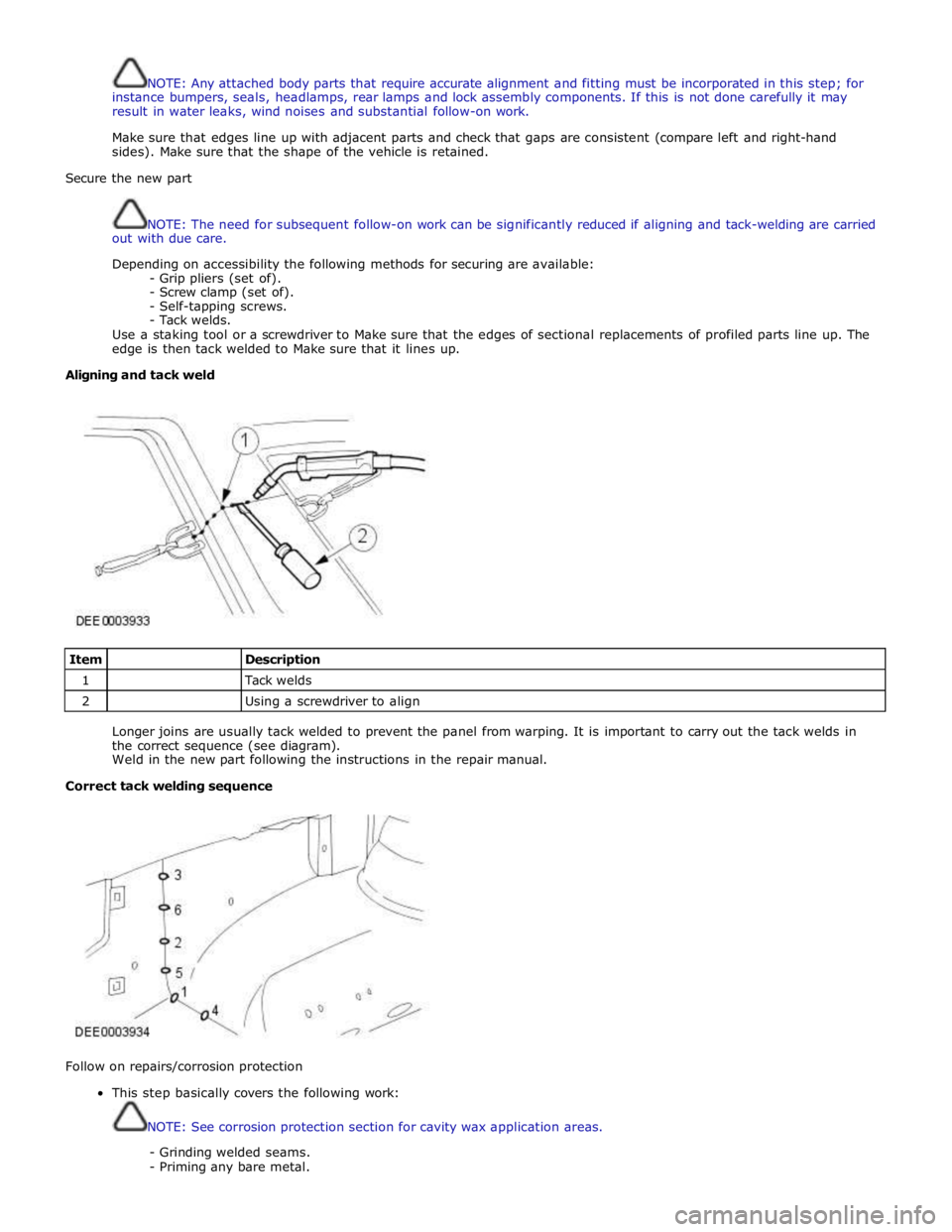
Use a staking tool or a screwdriver to Make sure that the edges of sectional replacements of profiled parts line up. The
edge is then tack welded to Make sure that it lines up.
Aligning and tack weld
Item
Description 1
Tack welds 2
Using a screwdriver to align
Longer joins are usually tack welded to prevent the panel from warping. It is important to carry out the tack welds in
the correct sequence (see diagram).
Weld in the new part following the instructions in the repair manual.
Correct tack welding sequence
Follow on repairs/corrosion protection
This step basically covers the following work:
NOTE: See corrosion protection section for cavity wax application areas.
- Grinding welded seams.
- Priming any bare metal.