2010 JAGUAR XFR diagram
[x] Cancel search: diagramPage 2352 of 3039
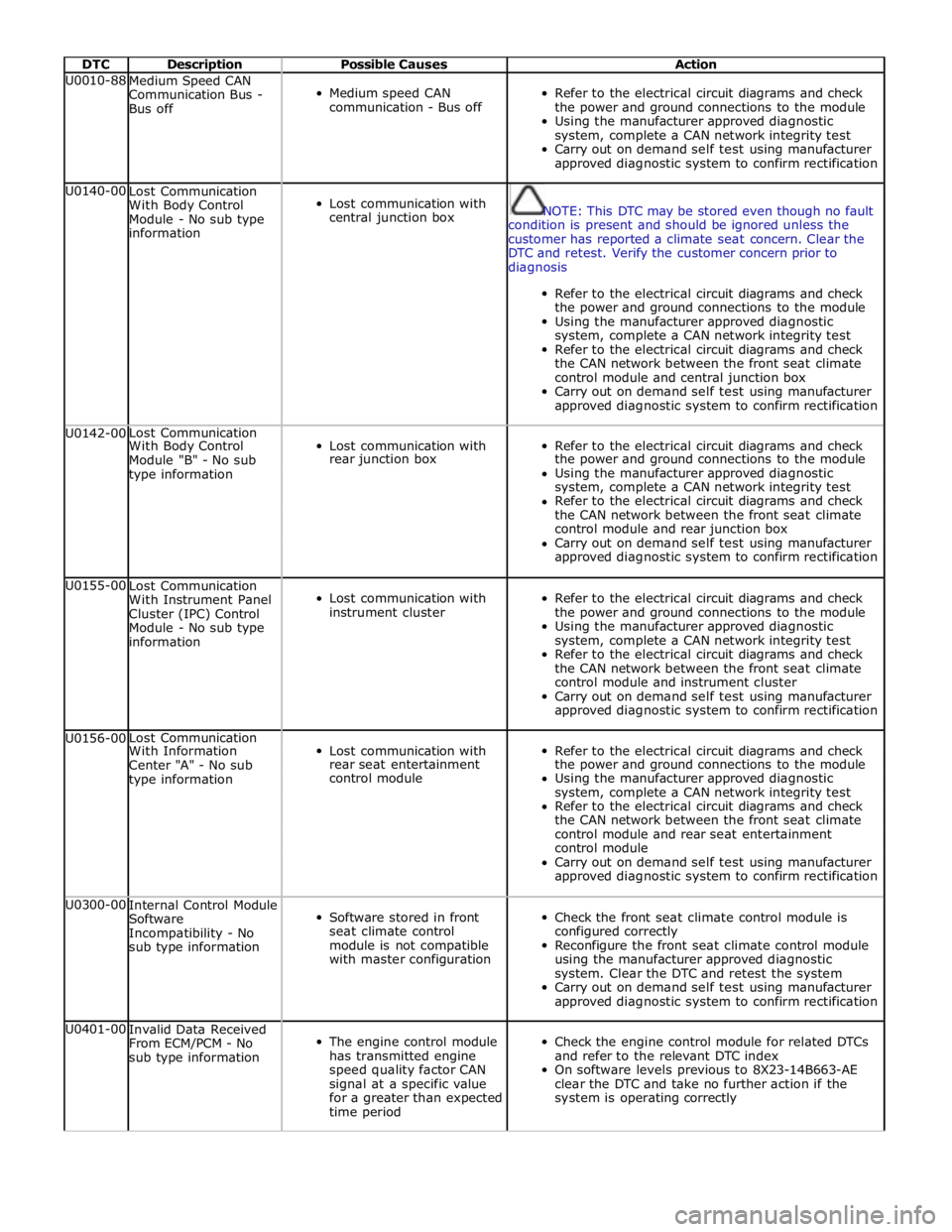
DTC Description Possible Causes Action U0010-88
Medium Speed CAN
Communication Bus -
Bus off
Medium speed CAN
communication - Bus off
Refer to the electrical circuit diagrams and check
the power and ground connections to the module
Using the manufacturer approved diagnostic
system, complete a CAN network integrity test
Carry out on demand self test using manufacturer
approved diagnostic system to confirm rectification U0140-00
Lost Communication
With Body Control
Module - No sub type
information
Lost communication with
central junction box
NOTE: This DTC may be stored even though no fault
condition is present and should be ignored unless the
customer has reported a climate seat concern. Clear the
DTC and retest. Verify the customer concern prior to
diagnosis
Refer to the electrical circuit diagrams and check
the power and ground connections to the module
Using the manufacturer approved diagnostic
system, complete a CAN network integrity test
Refer to the electrical circuit diagrams and check
the CAN network between the front seat climate
control module and central junction box
Carry out on demand self test using manufacturer
approved diagnostic system to confirm rectification U0142-00 Lost Communication
Lost communication with
Refer to the electrical circuit diagrams and check With Body Control Module "B" - No sub rear junction box the power and ground connections to the module type information Using the manufacturer approved diagnostic system, complete a CAN network integrity test Refer to the electrical circuit diagrams and check the CAN network between the front seat climate control module and rear junction box Carry out on demand self test using manufacturer approved diagnostic system to confirm rectification U0155-00
Lost Communication
With Instrument Panel
Cluster (IPC) Control
Module - No sub type
information
Lost communication with
instrument cluster
Refer to the electrical circuit diagrams and check
the power and ground connections to the module
Using the manufacturer approved diagnostic
system, complete a CAN network integrity test
Refer to the electrical circuit diagrams and check
the CAN network between the front seat climate
control module and instrument cluster
Carry out on demand self test using manufacturer
approved diagnostic system to confirm rectification U0156-00 Lost Communication
Lost communication with
Refer to the electrical circuit diagrams and check With Information Center "A" - No sub rear seat entertainment the power and ground connections to the module type information control module Using the manufacturer approved diagnostic system, complete a CAN network integrity test Refer to the electrical circuit diagrams and check the CAN network between the front seat climate control module and rear seat entertainment control module Carry out on demand self test using manufacturer approved diagnostic system to confirm rectification U0300-00
Internal Control Module
Software
Incompatibility - No
sub type information
Software stored in front
seat climate control
module is not compatible
with master configuration
Check the front seat climate control module is
configured correctly
Reconfigure the front seat climate control module
using the manufacturer approved diagnostic
system. Clear the DTC and retest the system
Carry out on demand self test using manufacturer
approved diagnostic system to confirm rectification U0401-00
Invalid Data Received
From ECM/PCM - No
sub type information
The engine control module
has transmitted engine
speed quality factor CAN
signal at a specific value
for a greater than expected
time period
Check the engine control module for related DTCs
and refer to the relevant DTC index
On software levels previous to 8X23-14B663-AE
clear the DTC and take no further action if the
system is operating correctly
Page 2353 of 3039
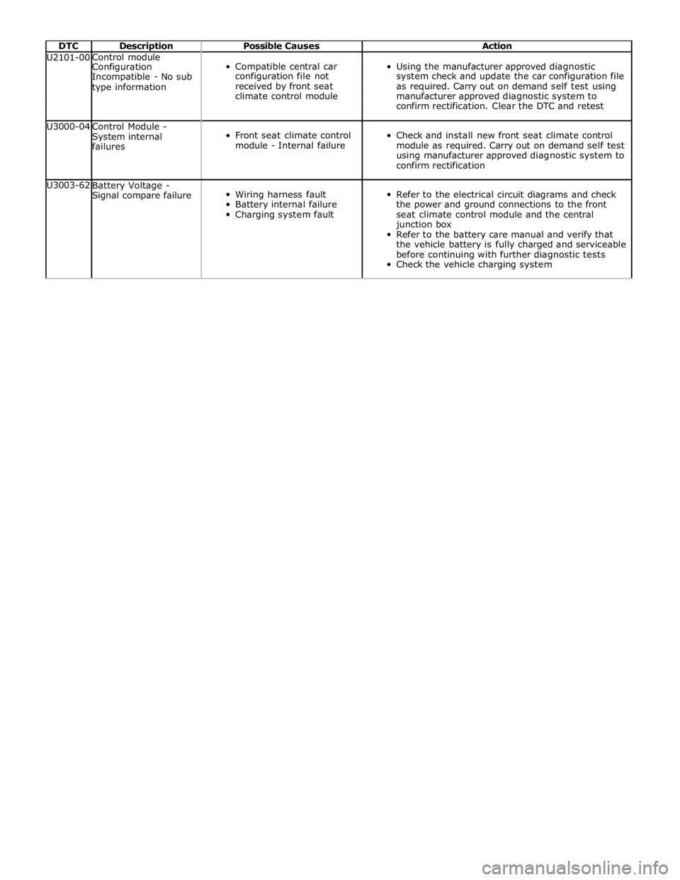
DTC Description Possible Causes Action U2101-00 Control module
Compatible central car
Using the manufacturer approved diagnostic Configuration Incompatible - No sub configuration file not system check and update the car configuration file type information received by front seat as required. Carry out on demand self test using climate control module manufacturer approved diagnostic system to confirm rectification. Clear the DTC and retest U3000-04
Control Module -
System internal
failures
Front seat climate control
module - Internal failure
Check and install new front seat climate control
module as required. Carry out on demand self test
using manufacturer approved diagnostic system to
confirm rectification U3003-62
Battery Voltage -
Signal compare failure
Wiring harness fault
Battery internal failure
Charging system fault
Refer to the electrical circuit diagrams and check
the power and ground connections to the front
seat climate control module and the central
junction box
Refer to the battery care manual and verify that
the vehicle battery is fully charged and serviceable
before continuing with further diagnostic tests
Check the vehicle charging system
Page 2414 of 3039
Published: 24-Jan-2013
Glass, Frames and Mechanisms - Glass, Frames and Mechanisms - System
Operation and Component Description
Description and Operation
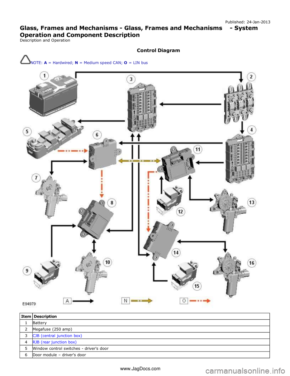
Control Diagram
NOTE: A = Hardwired; N = Medium speed CAN; O = LIN bus
Item Description 1 Battery 2 Megafuse (250 amp) 3 CJB (central junction box) 4 RJB (rear junction box) 5 Window control switches - driver's door 6 Door module – driver's door www.JagDocs.com
Page 2499 of 3039
NOTE: Test as a single component to ensure that the door latch is not replaced unnecessarily, when another component
may be at fault 1 Remove the door trim panel as necessary
2 Disconnect harness from latch, check for corrosion or damage to both connectors at socket points and pins. Re-connect harness
ensuring robust assembly when all parts confirmed to be in
good order. If harness or latch connectors are damaged, install
new harness/latch as necessary. Test the system for normal
operation Check for normal operation, does latch function correctly? Yes
Re-assemble door trim and test for normal operation
No
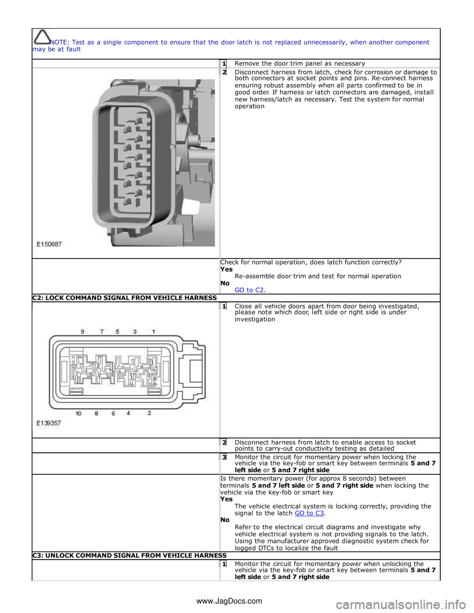
GO to C2. C2: LOCK COMMAND SIGNAL FROM VEHICLE HARNESS
1 Close all vehicle doors apart from door being investigated, please note which door, left side or right side is under
investigation 2 Disconnect harness from latch to enable access to socket points to carry-out conductivity testing as detailed 3 Monitor the circuit for momentary power when locking the vehicle via the key-fob or smart key between terminals 5 and 7
left side or 5 and 7 right side Is there momentary power (for approx 8 seconds) between
terminals 5 and 7 left side or 5 and 7 right side when locking the
vehicle via the key-fob or smart key Yes
The vehicle electrical system is locking correctly, providing the
signal to the latch GO to C3. No
Refer to the electrical circuit diagrams and investigate why
vehicle electrical system is not providing signals to the latch.
Using the manufacturer approved diagnostic system check for logged DTCs to localize the fault C3: UNLOCK COMMAND SIGNAL FROM VEHICLE HARNESS 1 Monitor the circuit for momentary power when unlocking the vehicle via the key-fob or smart key between terminals 5 and 7
left side or 5 and 7 right side www.JagDocs.com
Page 2500 of 3039
Is there momentary power (for approx 8 seconds) between
terminals 5 and 7 left side and 5 and 7 right side when unlocking
the vehicle via the key-fob or smart key? Yes
The vehicle electrical system is unlocking correctly, providing
the signal to the latch GO to C4. No
Refer to the electrical circuit diagrams and investigate why
vehicle electrical system is not providing signals to the latch.
Using the manufacturer approved diagnostic system check for
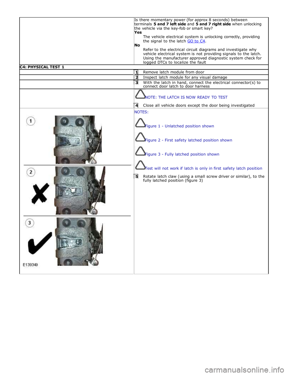
logged DTCs to localize the fault C4: PHYSICAL TEST 1 1 Remove latch module from door 2 Inspect latch module for any visual damage 3 With the latch in hand, connect the electrical connector(s) to connect door latch to door harness
NOTE: THE LATCH IS NOW READY TO TEST 4 Close all vehicle doors except the door being investigated NOTES:
Figure 1 - Unlatched position shown
Figure 2 - First safety latched position shown
Figure 3 - Fully latched position shown
Test will not work if latch is only in first safety latch position 5 Rotate latch claw (using a small screw driver or similar), to the fully latched position (figure 3)
Page 2536 of 3039
Published: 11-May-2011
Wipers and Washers - Wipers and Washers - System Operation and
Component Description
Description and Operation
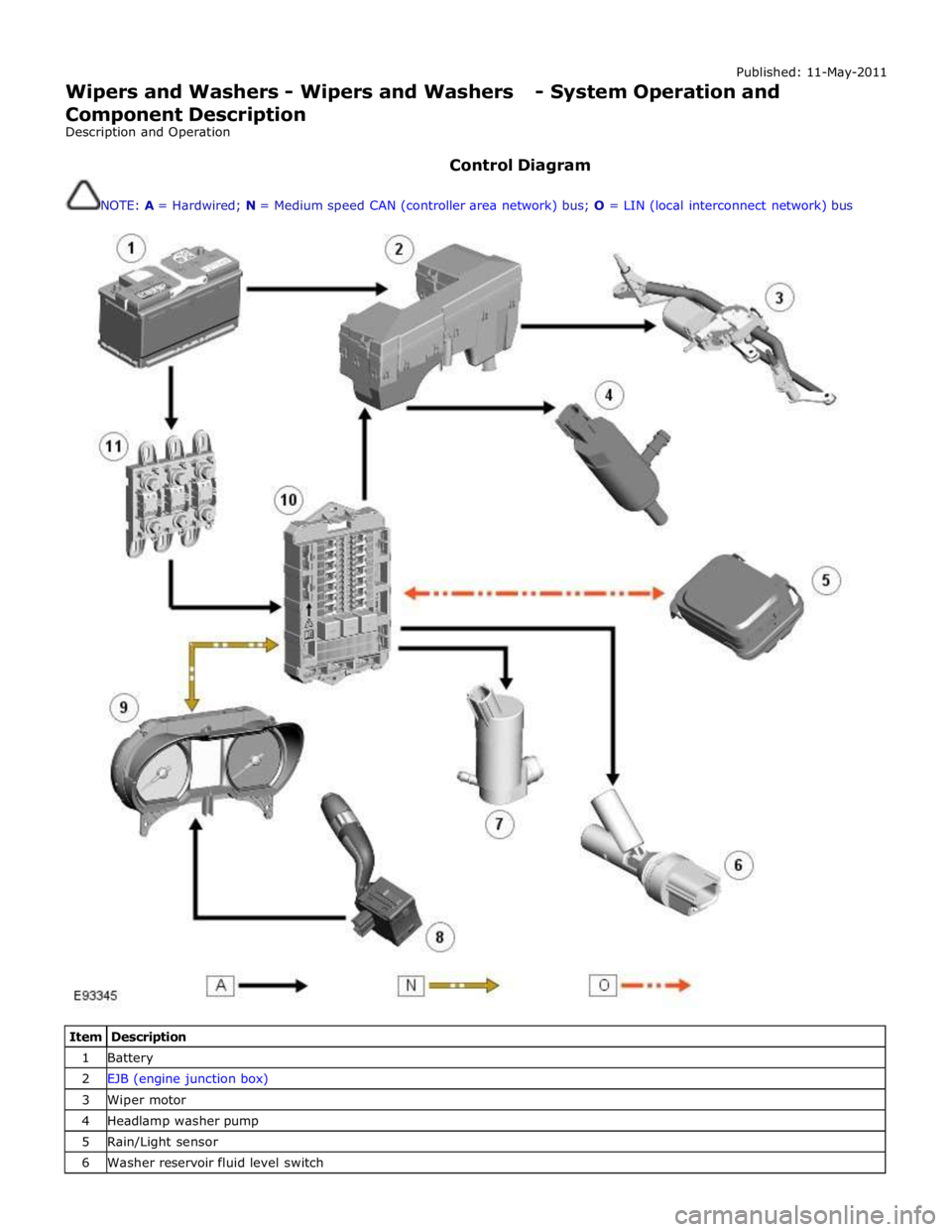
Control Diagram
NOTE: A = Hardwired; N = Medium speed CAN (controller area network) bus; O = LIN (local interconnect network) bus
Item Description 1 Battery 2 EJB (engine junction box) 3 Wiper motor 4 Headlamp washer pump 5 Rain/Light sensor 6 Washer reservoir fluid level switch
Page 2544 of 3039

DTC Description Possible Cause Action circuit - short to power
circuit diagrams and check wiper On/Off relay control circuit for
short to power B109514
Wiper On/Off
Relay
Wiper On/Off relay control
circuit - short to ground,
open circuit Refer to the electrical circuit diagrams and check wiper On/Off
relay control circuit for short to ground, open circuit B109612
Wiper High/Low
Relay
Wiper Fast/Slow relay
control circuit - short to
power Carry out any pinpoint tests associated with this DTC using the
manufacturer approved diagnostic system. Refer to the electrical
circuit diagrams and check wiper Fast/Slow relay control circuit for
short to power B109614
Wiper High/Low
Relay
Wiper Fast/Slow relay
control circuit - short to
ground, open circuit Refer to the electrical circuit diagrams and check wiper Fast/Slow
relay control circuit for short to ground, open circuit B10AD09 Rain Sensor
Component failures Carry out any pinpoint tests associated with this DTC using the
manufacturer approved diagnostic system. Suspect the rain/light
sensor, check and install a new sensor as required B10AD11 Rain Sensor
Rain/light sensor power
circuit - short to ground Carry out any pinpoint tests associated with this DTC using the
manufacturer approved diagnostic system. Refer to the electrical
circuit diagrams and check rain/light sensor power circuit for short
to ground B10AD96 Rain Sensor
Component internal
failure Suspect the rain/light sensor, check and install a new sensor as
required B117712
Screenwash
Level Switch
Screenwash level switch
signal circuit - short to
power Refer to the electrical circuit diagrams and check screenwash level
switch signal circuit for short to power B1C4513
Front Wiper Park
Position Switch
Windshield wiper motor
park switch signal circuit -
open circuit Refer to the electrical circuit diagrams and check windshield wiper
motor park switch signal circuit for open circuit B1C4523
Front Wiper Park
Position Switch
Signal stuck low Refer to the electrical circuit diagrams and check front wiper park
position switch input circuit for short, open circuit B1C7812 Powerwash Relay
Powerwash relay control
circuit - short to power Refer to the electrical circuit diagrams and check powerwash relay
control circuit for short to power B1C7814 Powerwash Relay
Powerwash relay control
circuit - short to ground,
open circuit Refer to the electrical circuit diagrams and check powerwash relay
control circuit for short to ground, open circuit B1C7911
Front Washer
Pump
Screenwash pump control
circuit - short to ground Refer to the electrical circuit diagrams and check screenwash
pump control circuit for short to ground B1C7913
Front Washer
Pump
Screenwash pump control
circuit - open circuit Carry out any pinpoint tests associated with this DTC using the
manufacturer approved diagnostic system. Refer to the electrical
circuit diagrams and check screenwash pump control circuit for open circuit www.JagDocs.com
Page 2561 of 3039
Published: 11-May-2011
Roof Opening Panel - Roof Opening Panel - System Operation and
Component Description
Description and Operation
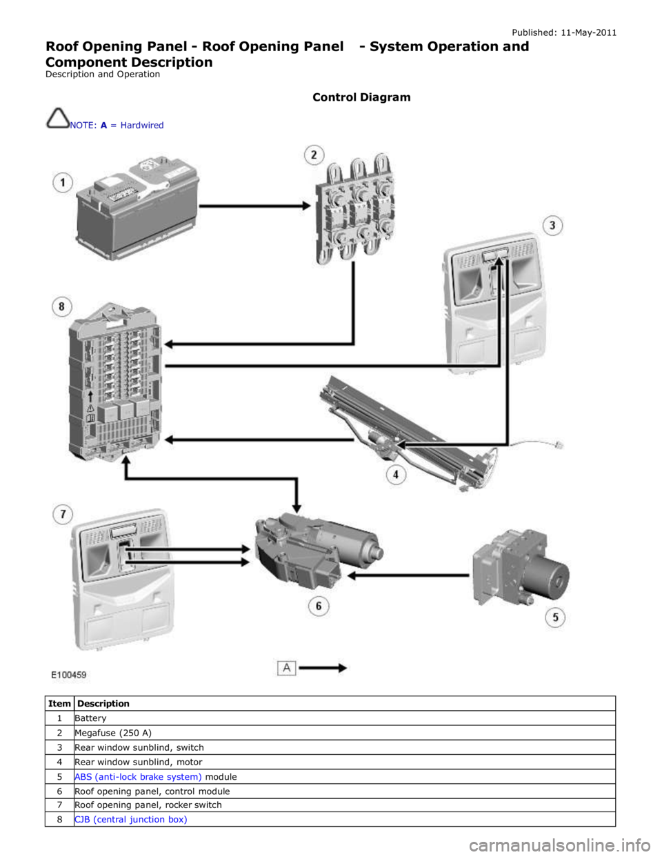
Control Diagram
NOTE: A = Hardwired
Item Description 1 Battery 2 Megafuse (250 A) 3 Rear window sunblind, switch 4 Rear window sunblind, motor 5 ABS (anti-lock brake system) module 6 Roof opening panel, control module 7 Roof opening panel, rocker switch 8 CJB (central junction box)