2010 JAGUAR XFR Rear Drive
[x] Cancel search: Rear DrivePage 2056 of 3039

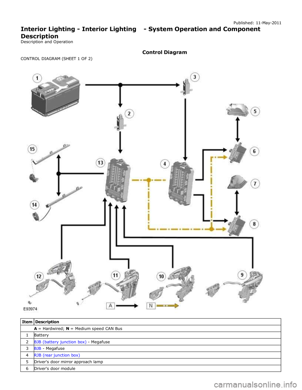
A = Hardwired; N = Medium speed CAN Bus 1 Battery 2 BJB (battery junction box) - Megafuse 3 BJB - Megafuse 4 RJB (rear junction box) 5 Driver's door mirror approach lamp 6 Driver's door module
Page 2058 of 3039

3 BJB - Megafuse 4 RJB 5 Glovebox lamp 6 Glovebox lamp switch 7 LH footwell lamp 8 RH footwell lamp 9 LH vanity mirror 10 RH vanity mirror 11 LH rear interior lamp 12 RH rear interior lamp 13 CJB 14 Ambience lighting LED's 15 LH map reading lamp 16 Courtesy lamp 17 RH map reading lamp
JUNCTION BOXES
Inputs System Operation
The CJB receives the following inputs which affect the operation of the interior lamps: Ignition mode
Lock/unlock
Luggage compartment lid latch switch
Door latch switches.
Outputs
The RJB outputs the following for the interior lighting system: Luggage compartment lamp power supply
Driver and passenger door module power supplies
Fade on and off grounds for front and rear overhead console interior lamps and footwell lamps
PWM (pulse width modulation) power output for the ambience lighting.
Interior Lamp Time-Out
The interior lamps are controlled by a timer within the CJB which allows a 60 second delay period for the lamps to remain active after the ignition mode has been changed to off power mode 0 or the vehicle has been unlocked. The interior lamp fade
off is controlled by the RJBvia a delayed power off relay in the CJB. The following interior lamps are subject to the delay period:
Front overhead console interior lamp
Rear interior lamps
Footwell lamps
Door mirror approach lamps.
The timer delay is activated when the CJB receives one of the following signals: An unlock signal from the Smart Key via the keyless vehicle module.
Ignition mode is changed from the crank power mode 9 or ignition power mode 6 to the accessory power mode 4 to the
off power mode 0.
If a second occurrence of the above actions occurs within the timer period, the timer will be rest and the delay period timer will
restart.
The timer delay is deactivated when the CJB receives one of the following signals: A lock signal from the Smart Key via the keyless vehicle module
Ignition mode is changed from the off power mode 0 to the accessory power mode 4 or ignition power mode 6
The CJB receives a door opened signal (even if that door is subsequently closed). Battery Saver
The battery saver provides an automatic shut-off of the interior lamps after a period of 15 minutes in order to prevent
excessive power drain on the battery.
When the ignition mode is changed from the ignition power mode 6 or accessory power mode 4 to the off power mode 0, the
CJB starts a timer which de-energizes a delayed power off relay in the CJB, removing the power supply to the interior lamps after a period of 15 minutes, switching off all or any interior lamps which have remained on for any reason.
Page 2060 of 3039

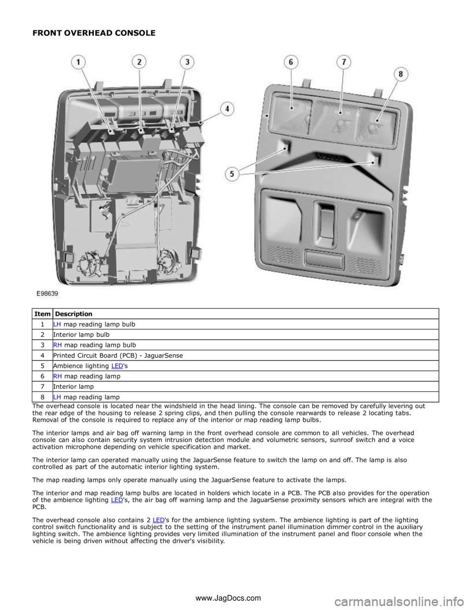
1 LH map reading lamp bulb 2 Interior lamp bulb 3 RH map reading lamp bulb 4 Printed Circuit Board (PCB) - JaguarSense 5 Ambience lighting LED's 6 RH map reading lamp 7 Interior lamp 8 LH map reading lamp The overhead console is located near the windshield in the head lining. The console can be removed by carefully levering out
the rear edge of the housing to release 2 spring clips, and then pulling the console rearwards to release 2 locating tabs.
Removal of the console is required to replace any of the interior or map reading lamp bulbs.
The interior lamps and air bag off warning lamp in the front overhead console are common to all vehicles. The overhead
console can also contain security system intrusion detection module and volumetric sensors, sunroof switch and a voice
activation microphone depending on vehicle specification and market.
The interior lamp can operated manually using the JaguarSense feature to switch the lamp on and off. The lamp is also
controlled as part of the automatic interior lighting system.
The map reading lamps only operate manually using the JaguarSense feature to activate the lamps.
The interior and map reading lamp bulbs are located in holders which locate in a PCB. The PCB also provides for the operation
of the ambience lighting LED's, the air bag off warning lamp and the JaguarSense proximity sensors which are integral with the PCB.
The overhead console also contains 2 LED's for the ambience lighting system. The ambience lighting is part of the lighting control switch functionality and is subject to the setting of the instrument panel illumination dimmer control in the auxiliary
lighting switch. The ambience lighting provides very limited illumination of the instrument panel and floor console when the
vehicle is being driven without affecting the driver's visibility. www.JagDocs.com
Page 2069 of 3039

5 RJB (rear junction box) 6 Battery monitoring system module 7 Rear view camera 8 TCM (transmission control module) 9 Generator 10 Driver's door switch pack 11 Rear door control module 12 Driver's door control module 13 ECM (engine control module) 14 Electronic transmission selector 15 Driver's seat module 16 Driver's seat switch pack 17 Rear door control module 18 Front passenger door control module 19 Clockspring 20 Audio and telephone steering wheel switches 21 Instrument cluster 22 Start control module
Page 2089 of 3039

DTC Description Possible Cause Action B115B11 Driver Seat Heater
Driver seat heater supply circuit
- short to ground Carry out any pinpoint tests associated with this DTC
using the manufacturer approved diagnostic system.
Refer to the electrical circuit diagrams and check driver
seat heater supply circuit for short to ground B115B15 Driver Seat Heater
Driver seat heater supply circuit
- short to power, open circuit Carry out any pinpoint tests associated with this DTC
using the manufacturer approved diagnostic system.
Refer to the electrical circuit diagrams and check driver
seat heater supply circuit for short to power, open circuit B117513
Driver Door Ajar
Switch
Driver door ajar switch signal
circuit - open circuit Refer to the electrical circuit diagrams and check driver
door ajar switch signal circuit for open circuit B117613
Passenger Door
Ajar Switch
Passenger door ajar switch
signal circuit - open circuit Refer to the electrical circuit diagrams and check
passenger door ajar switch signal circuit for open circuit B117712
Screenwash Level
Switch
Screenwash level switch signal
circuit - short to power Refer to the electrical circuit diagrams and check
screenwash level switch signal circuit for short to power B11C013
Driver Side Rear
Door Ajar Switch
Left rear door ajar switch signal
circuit - open circuit Refer to the electrical circuit diagrams and check left rear
door ajar switch signal circuit for open circuit B11C113
Passenger Side
Rear Door Ajar
Switch
Right rear door ajar switch
signal circuit - open circuit Refer to the electrical circuit diagrams and check right
rear door ajar switch signal circuit for open circuit B122223
Master Lock/Unlock
Switch
Master lock or unlock switch
digital input circuit - signal
stuck low Refer to the electrical circuit diagrams and check master
lock and unlock switch digital input circuits for short to
ground, open circuit B123711
Gear Shift Module
Early Wake-up
Transmission shift module
wake-up control circuit - short
to ground Carry out any pinpoint tests associated with this DTC
using the manufacturer approved diagnostic system.
Refer to the electrical circuit diagrams and check
transmission shift module wake-up control circuit for
short to ground B123712
Gear Shift Module
Early Wake-up
Transmission shift module
wake-up control circuit - short
to power Refer to the electrical circuit diagrams and check
transmission shift module wake-up control circuit for
short to power B123713
Gear Shift Module
Early Wake-up
Transmission shift module
wake-up control circuit - open
circuit Refer to the electrical circuit diagrams and check
transmission shift module wake-up control circuit for
open circuit B123E13 Crank Enable
OK to crank signal circuit -
open circuit Refer to the electrical circuit diagrams and check OK to
crank signal circuit for open circuit B1A8596
Ambient Light
Sensor
Light sensor internal electronic
failure Check and install a new sensor as required B1C4513
Front Wiper Park
Position Switch
Windshield wiper motor park
switch signal circuit - open
circuit Refer to the electrical circuit diagrams and check
windshield wiper motor park switch signal circuit for open
circuit B1C4523
Front Wiper Park
Position Switch
Signal stuck low Refer to the electrical circuit diagrams and check front
wiper park position switch input circuit for short, open
circuit B1C7812 Powerwash Relay
Powerwash relay control circuit
- short to power Refer to the electrical circuit diagrams and check
powerwash relay control circuit for short to power B1C7814 Powerwash Relay
Powerwash relay control circuit
- short to ground, open circuit Refer to the electrical circuit diagrams and check
powerwash relay control circuit for short to ground, open
circuit B1C7911 Front Washer Pump
Screenwash pump control
circuit - short to ground Refer to the electrical circuit diagrams and check
screenwash pump control circuit for short to ground
Page 2093 of 3039

DTC Description Possible Cause Action U300362 Battery Voltage
Mis-match in battery voltage,
of 2 volts or more, between
CJB and RJB Carry out any pinpoint tests associated with this DTC
using the manufacturer approved diagnostic system. Rear Junction Box (RJB)
CAUTIONS:
Diagnosis by substitution from a donor vehicle is NOT acceptable. Substitution of control modules does not guarantee
confirmation of a fault, and may also cause additional faults in the vehicle being tested and/or the donor vehicle
When probing connectors to take measurements in the course of the pinpoint tests, use the adaptor kit, part number
3548-1358-00
NOTES:
If the control module or a component is suspect and the vehicle remains under manufacturer warranty, refer to the
warranty policy and procedures manual (section B1.2), or determine if any prior approval programme is in operation, prior to
the installation of a new module/component
Generic scan tools may not read the codes listed, or may read only 5-digit codes. Match the 5 digits from the scan tool to
the first 5 digits of the 7-digit code listed to identify the fault (the last 2 digits give extra information read by the
manufacturer-approved diagnostic system)
When performing voltage or resistance tests, always use a digital multimeter accurate to three decimal places and with a
current calibration certificate. When testing resistance, always take the resistance of the digital multimeter leads into account
Check and rectify basic faults before beginning diagnostic routines involving pinpoint tests
Inspect connectors for signs of water ingress, and pins for damage and/or corrosion
If diagnostic trouble codes are recorded and, after performing the pinpoint tests, a fault is not present, an intermittent
concern may be the cause. Always check for loose connections and corroded terminals
Where an 'on demand self-test' is referred to, this can be accessed via the 'diagnostic trouble code monitor' tab on the
manufacturers approved diagnostic system
Check DDW for open campaigns. Refer to the corresponding bulletins and SSMs which may be valid for the specific
customer complaint and carry out the recommendations as required
DTC Description Possible Causes Action P046011
Fuel Level Sensor
A Circuit
Fuel level sensor A
analogue input circuit -
short to ground Carry out any pinpoint test associated with this DTC using the
manufacturer approved diagnostic system. Refer to the electrical
circuit diagrams and check fuel level sensor A analogue input
circuit for short to ground P046015
Fuel Level Sensor
A Circuit
Fuel level sensor A
analogue input circuit -
short to power, open
circuit Carry out any pinpoint test associated with this DTC using the
manufacturer approved diagnostic system. Refer to the electrical
circuit diagrams and check fuel level sensor A analogue input
circuit for short to power, open circuit P057112
Brake Switch A
Circuit
Footbrake switch digital
input signal circuits -
short to power Refer to the electrical circuit diagrams and check footbrake switch
digital input signal circuits for short to power P123012
Fuel Pump Low
Speed
Malfunction
(VLCM)
High Side output not
driven - Diagnosis
feedback indicates output
is short to power Refer to the electrical circuit diagrams and check fuel pump
delivery module for short to power
Page 2095 of 3039

DTC Description Possible Causes Action Write target SID
synchronisation error
following re-programming
Noise/EMC related error B100A63
Fuel Pump
Authorisation
RJB fault
Low speed CAN fault
Instrument cluster fault
Low battery voltage <9V Check power and ground supplies to RJB and instrument cluster.
Check CAN communications between RJB and instrument cluster.
Check battery is in fully charged and serviceable condition, refer
to the battery care manual B102612
Steering Column
Lock
Steering column lock
ground circuit - short to
power Refer to the electrical circuit diagrams and check steering column
lock ground circuit for short to power B108783 LIN Bus "A"
The checksum of the
received LIN frame is
incorrect Check the battery monitoring system and rear parking aid system
for DTCs and refer to relevant DTC Index B108786 LIN Bus "A"
The header of the LIN
message received is
incorrect Carry out any pinpoint test associated with this DTC using the
manufacturer approved diagnostic system. Check the battery
monitoring system and rear parking aid system for DTCs and
refer to relevant DTC Index B108788 LIN Bus "A"
Battery monitoring
system LIN circuit - short
to ground, power Carry out any pinpoint test associated with this DTC using the
manufacturer approved diagnostic system. Refer to the electrical
circuit diagrams and check battery monitoring system LIN circuit
for short to ground, power B108A23 Start Button
Start/Stop switch digital
input signal circuit -
stuck low Carry out any pinpoint test associated with this DTC using the
manufacturer approved diagnostic system. Refer to the electrical
circuit diagrams and check Start/Stop switch digital input signal
circuit for short to ground B10A111 Trailer Tow
Detection
Trailer tow detection
digital input circuit -
short to ground Carry out any pinpoint test associated with this DTC using the
manufacturer approved diagnostic system. Refer to the electrical
circuit diagrams and check trailer tow detection digital input
circuit for short to ground B10AF12 Blower Fan Relay
High Side output not
driven - Diagnosis
feedback indicates output
is short to power Refer to the electrical circuit diagrams and check blower motor
supply circuit for short to power B10AF14 Blower Fan Relay
High Side output not
driven - Diagnosis
feedback indicates output
is short to ground, open
circuit Refer to the electrical circuit diagrams and check blower motor
supply circuit for short to ground, open circuit B10AF93 Blower Fan Relay
High Side output not
driven - Diagnosis
feedback indicates output
is at open load or short
to power Carry out any pinpoint test associated with this DTC using the
manufacturer approved diagnostic system. Refer to the electrical
circuit diagrams and check blower motor supply circuit for short
to power, open circuit B10DD11 Airbag Deployed
Airbag deployed digital
input signal circuit - short
to ground Carry out any pinpoint test associated with this DTC using the
manufacturer approved diagnostic system. Refer to the electrical
circuit diagrams and check airbag deployed digital input signal
circuit for short to ground B10DD15 Airbag Deployed
Airbag deployed digital
input signal circuit - short
to power, open circuit Carry out any pinpoint test associated with this DTC using the
manufacturer approved diagnostic system. Refer to the electrical
circuit diagrams and check airbag deployed digital input signal
circuit for short to power, open circuit B10DD38 Airbag Deployed
Signal frequency incorrect Check the RCM for related DTCs and refer to the relevant DTC
Index B10DE11
Low Fuel Warning
Switch
Diesel run-dry switch
analogue input circuit -
short to ground Carry out any pinpoint test associated with this DTC using the
manufacturer approved diagnostic system. Refer to the electrical
circuit diagrams and check diesel run-dry switch analogue input
circuit for short to ground www.JagDocs.com
Page 2099 of 3039

DTC Description Possible Causes Action B124812
Right Rear Turn
Indicator
Right rear turn signal
lamp control circuit -
short to power Refer to the electrical circuit diagrams and check right rear turn
signal lamp control circuit for short to power B124813
Right Rear Turn
Indicator
Right rear turn signal
lamp control circuit -
open circuit Refer to the electrical circuit diagrams and check right rear turn
signal lamp control circuit for open circuit B1248-15
Right Rear Turn
Indicator - circuit
short to battery
or open
Right rear turn signal
lamp control circuit -
short circuit to power,
open circuit, high
resistance
Refer to electrical circuit diagrams and check right rear
turn signal lamp control circuit for short circuit to power,
open circuit, high resistance. Repair wiring harness as
required. Clear DTC and retest B126113
Fuel Flap/Door
Release Switch
Fuel filler flap digital
input signal circuit - open
circuit Refer to the electrical circuit diagrams and check fuel filler flap
digital input signal circuit for open circuit B1A7911 Rear Fog Lamp
Rear fog lamp control
circuit - short to ground Carry out any pinpoint test associated with this DTC using the
manufacturer approved diagnostic system. Refer to the electrical
circuit diagrams and check rear fog lamp control circuit for short
to ground B1A7912 Rear Fog Lamp
Rear fog lamp control
circuit - short to power Refer to the electrical circuit diagrams and check rear fog lamp
control circuit for short to power B1A7913 Rear Fog Lamp
Rear fog lamp control
circuit - open circuit Refer to the electrical circuit diagrams and check rear fog lamp
control circuit for open circuit B1C5512 Horn Relay
Horn control circuit -
short to power Refer to the electrical circuit diagrams and check horn control
circuit for short to power B1C5514 Horn Relay
Horn control circuit -
short to ground, open
circuit Refer to the electrical circuit diagrams and check horn control
circuit for short to ground, open circuit B1C8312 Rear Defog Relay
High Side output not
driven - diagnosis
feedback indicates output
is short to power Refer to the electrical circuit diagrams and check heated rear
window power supply circuit for short to power B1C8314 Rear Defog Relay
High Side output not
driven - diagnosis
feedback indicates output
is short to ground, open
circuit Refer to the electrical circuit diagrams and check heated rear
window power supply circuit for short to ground, open circuit B1C8393 Rear Defog Relay
High Side output not
driven - diagnosis
feedback indicates output
is at open load or short
to power Carry out any pinpoint test associated with this DTC using the
manufacturer approved diagnostic system. Refer to the electrical
circuit diagrams and check heated rear window power supply
circuit for open load and short to power B1C9112
Fuel Flap/Door
Lock Relay Coil
Circuit
Fuel filler flap locking
motor control circuit -
short to power Refer to the electrical circuit diagrams and check fuel filler flap
locking motor control circuit for short to power B1C9114
Fuel Flap/Door
Lock Relay Coil
Circuit
Fuel filler flap locking
motor control circuit -
short to ground, open
circuit Refer to the electrical circuit diagrams and check fuel filler flap
locking motor control circuit for short to ground, open circuit B1D3512 Hazard Switch
Hazard warning lamp
switch digital input circuit
- short to power Refer to the electrical circuit diagrams and check hazard warning
lamp switch digital input circuit for short to power