2010 JAGUAR XFR Rear Drive
[x] Cancel search: Rear DrivePage 5 of 3039

Disassembly and AssemblyShock Absorber and Spring Assembly204-04: Wheels and TiresSpecificationDescription and OperationComponent Location
Overview
System Operation and Component DescriptionDiagnosis and TestingWheels and TiresRemoval and InstallationTire Low Pressure Sensor
Tire Pressure Monitoring System (TPMS) Front Antenna
Tire Pressure Monitoring System (TPMS) Rear Antenna
Tire Pressure Monitoring System (TPMS) Module
Tire Pressure Monitoring System (TPMS) Receiver
Wheel and Tire204-05: Vehicle Dynamic Suspension
Description and OperationComponent Location - V8 5.0L Petrol/V8 S/C 5.0L Petrol
Overview - V8 5.0L Petrol/V8 S/C 5.0L Petrol
System Operation and Component Description - V8 5.0L Petrol/V8 S/C 5.0L PetrolDiagnosis and TestingVehicle Dynamic SuspensionRemoval and InstallationAdaptive Damping Module
Front Suspension Vertical Accelerometer
Rear Suspension Vertical Accelerometer204-06: Ride and Handling Optimization
Description and OperationComponent Location
Overview
System Operation and Component Description205: Driveline
205-00: Driveline System - General Information
Diagnosis and TestingDriveline SystemGeneral ProceduresDriveline Angle Inspection205-01: DriveshaftSpecification
Page 6 of 3039

Component Location
Overview
System Operation and Component Description
Component Location
Overview
System Operation and Component DescriptionDiagnosis and TestingDriveshaftGeneral ProceduresDriveshaft Runout and BalancingRemoval and InstallationDriveshaft - V8 5.0L Petrol/V8 S/C 5.0L Petrol205-02: Rear Drive Axle/DifferentialSpecification - TDV6 3.0L Diesel /V8 5.0L Petrol/V8 S/C 5.0L PetrolDescription and OperationComponent Location
Overview
System Operation and Component DescriptionDiagnosis and TestingRear Drive Axle and DifferentialGeneral ProceduresDifferential Draining and FillingRemoval and InstallationDifferential Case - TDV6 3.0L Diesel /V8 5.0L Petrol/V8 S/C 5.0L Petrol
Differential Front Bushing - TDV6 3.0L Diesel /V8 5.0L Petrol/V8 S/C 5.0L Petrol
Drive Pinion Seal
Differential Locking Motor205-05: Rear Drive HalfshaftsSpecificationDescription and OperationComponent Location
Overview
System Operation and Component DescriptionDiagnosis and TestingRear Drive HalfshaftsRemoval and InstallationRear Halfshaft - TDV6 3.0L Diesel /V8 5.0L Petrol/V8 S/C 5.0L Petrol
Inner Constant Velocity (CV) Joint Boot (47.10.33)
Outer Constant Velocity (CV) Joint Boot (47.10.32)206: Brake System
206-00: Brake System - General InformationSpecification - TDV6 3.0L Diesel /V8 5.0L Petrol/V8 S/C 5.0L PetrolDescription and Operation
Page 11 of 3039

Overview
System Operation and Component DescriptionDiagnosis and TestingEngineGeneral ProceduresEngine Oil Draining and Filling
Engine Oil Vacuum Draining and Filling
Fuel Pump Camshaft Timing Check
Fuel Pump Camshaft Timing Adjustment
Valve Clearance Check
Valve Clearance AdjustmentRemoval and InstallationCamshaft LH
Camshaft RH
Crankshaft Front Seal
Crankshaft Pulley
Crankshaft Rear Seal
Cylinder Head LH
Cylinder Head RH
Engine Mount LH
Engine Mount RH
Exhaust Manifold LH
Exhaust Manifold RH
Flexplate
Oil Cooler
Oil Filter Element
Oil Pan
Oil Pan Extension
Oil Pump
Timing Cover
Timing Drive Components
Valve Cover LH
Valve Cover RH
Cylinder Block Oil Gallery Plug
Fuel Pump Camshaft - Assembly Part Number: INA Timing Drive
Fuel Pump Camshaft - Assembly Part Number: Tsubaki Timing Drive
Lower Timing Cover
ValvesRemovalEngineInstallationEngine
Page 24 of 3039

System Operation and Component DescriptionDiagnosis and TestingAnti-Theft - ActiveRemoval and InstallationAnti-Theft Alarm Horn (86.52.03)419-01B: Anti-Theft - Passive
Description and OperationComponent Location
Overview
System Operation and Component DescriptionDiagnosis and TestingAnti-Theft - Passive419-05: Telematics
Diagnosis and TestingTelematics419-07: Navigation System
Description and Operation Diagnosis and TestingNavigation SystemRemoval and InstallationNavigation System Antenna (86.62.06)
Navigation System Module (86.62.05)419-08: Cellular Phone
Removal and InstallationBluetooth Module419-10: Multifunction Electronic ModulesSpecificationDescription and OperationComponent Location
Overview
System Operation and Component DescriptionDiagnosis and TestingDriver Door Module (DDM)
Remote Keyless Entry (RKE) Module
Passenger Door Module (PDM)Removal and InstallationDriver Door Module (DDM)
Driver Seat Module (DSM)
Passenger Door Module (PDM)
Rear Door Module (RDM)5: Body and Paint
501: Body and Paint
501-02: Front End Body Panels
Page 27 of 3039

Memory Seat Position Switch
Seat Base
Rear Seat Backrest Cover (76.70.48) (78.90.12)
Rear Seat Cushion (76.70.37)
Front Seat Height Adjustment Motor
Front Seat Control Switch
Front Seat Head Restraint Motor (86.75.17)
Rear Seat Bolster
Front Seat Backrest Cover Trim Panel501-11: Glass, Frames and MechanismsSpecificationDescription and OperationComponent Location
Overview
System Operation and Component DescriptionDiagnosis and TestingGlass, Frames and Mechanisms
Fixed Window GlassGeneral ProceduresDoor Window Motor InitializationRemoval and InstallationDriver Door Window Control Switch (86.25.03) (86.25.08)
Front Door Window Glass
Front Door Window Regulator and Motor (76.31.45)
Rear Door Fixed Window Glass
Rear Door Window Glass
Rear Door Window Regulator and Motor
Rear Window Glass
Windshield Glass
Door Window Regulator Motor (86.25.04)501-12: Instrument Panel and ConsoleSpecificationDescription and OperationComponent Location
Overview
System Operation and Component DescriptionRemoval and InstallationFloor Console
Floor Console Cup Holder
Floor Console Double Cup Holder
Floor Console Side Trim Panel
Glove Compartment
Page 55 of 3039

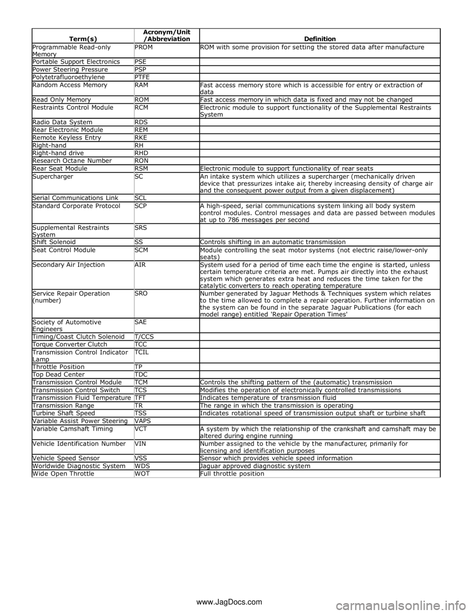
Programmable Read-only Memory PROM ROM with some provision for setting the stored data after manufacture Portable Support Electronics PSE Power Steering Pressure PSP Polytetrafluoroethylene PTFE Random Access Memory RAM
Fast access memory store which is accessible for entry or extraction of
data Read Only Memory ROM Fast access memory in which data is fixed and may not be changed Restraints Control Module RCM
Electronic module to support functionality of the Supplemental Restraints System Radio Data System RDS Rear Electronic Module REM Remote Keyless Entry RKE Right-hand RH Right-hand drive RHD Research Octane Number RON Rear Seat Module RSM Electronic module to support functionality of rear seats Supercharger SC
An intake system which utilizes a supercharger (mechanically driven
device that pressurizes intake air, thereby increasing density of charge air
and the consequent power output from a given displacement) Serial Communications Link SCL Standard Corporate Protocol SCP
A high-speed, serial communications system linking all body system
control modules. Control messages and data are passed between modules
at up to 786 messages per second Supplemental Restraints System SRS
Shift Solenoid SS Controls shifting in an automatic transmission Seat Control Module SCM
Module controlling the seat motor systems (not electric raise/lower-only seats) Secondary Air Injection AIR
System used for a period of time each time the engine is started, unless
certain temperature criteria are met. Pumps air directly into the exhaust
system which generates extra heat and reduces the time taken for the catalytic converters to reach operating temperature Service Repair Operation
(number) SRO
Number generated by Jaguar Methods & Techniques system which relates
to the time allowed to complete a repair operation. Further information on
the system can be found in the separate Jaguar Publications (for each
model range) entitled 'Repair Operation Times' Society of Automotive Engineers SAE
Timing/Coast Clutch Solenoid T/CCS Torque Converter Clutch TCC Transmission Control Indicator
Lamp TCIL
Throttle Position TP Top Dead Center TDC Transmission Control Module TCM Controls the shifting pattern of the (automatic) transmission Transmission Control Switch TCS Modifies the operation of electronically controlled transmissions Transmission Fluid Temperature TFT Indicates temperature of transmission fluid Transmission Range TR The range in which the transmission is operating Turbine Shaft Speed TSS Indicates rotational speed of transmission output shaft or turbine shaft Variable Assist Power Steering VAPS Variable Camshaft Timing VCT
A system by which the relationship of the crankshaft and camshaft may be
altered during engine running Vehicle Identification Number VIN
Number assigned to the vehicle by the manufacturer, primarily for licensing and identification purposes Vehicle Speed Sensor VSS Sensor which provides vehicle speed information Worldwide Diagnostic System WDS Jaguar approved diagnostic system Wide Open Throttle WOT Full throttle position www.JagDocs.com
Page 77 of 3039

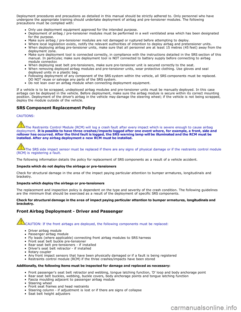
Deployment procedures and precautions as detailed in this manual should be strictly adhered to. Only personnel who have
undergone the appropriate training should undertake deployment of airbag and pre-tensioner modules. The following
precautions must be complied with:
Only use deployment equipment approved for the intended purpose.
Deployment of airbag / pre-tensioner modules must be performed in a well ventilated area which has been designated
for the purpose.
Make sure airbag / pre-tensioner modules are not damaged or ruptured before attempting to deploy.
Where local legislation exists, notify the relevant authorities of intention to deploy airbag and pretensioner units.
When deploying airbag pre-tensioner units, make sure that all personnel are at least 15 metres (45 feet) away from the
deployment zone.
Make sure deployment tool is connected correctly, in compliance with the instructions detailed in the SRS section of this
manual. In particular, make sure deployment tool is NOT connected to battery supply before connecting to airbag
module connector.
When deploying seat belt pre-tensioners, make sure pre-tensioner unit is secured correctly to the seat.
When removing deployed airbag modules and pre-tensioner units, wear protective clothing. Use gloves and seal
deployed units in a plastic bag.
Following deployment of any component of the SRS system within the vehicle, all SRS components must be replaced.
DO NOT reuse or salvage any parts of the SRS system.
Do not lean over an airbag module when connecting deployment equipment.
If a vehicle is to be scrapped, undeployed airbag modules and pre-tensioner units must be manually deployed. In this case
airbags can be deployed in the vehicle. Before deployment, make sure the airbag module is secure within its correct mounting
position. Deployment of the driver's airbag in the vehicle may damage the steering wheel; if the vehicle is not being scrapped,
deploy the module outside of the vehicle.
SRS Component Replacement Policy
CAUTIONS:
The Restraints Control Module (RCM) will log a crash fault after every impact which is severe enough to cause airbag
deployment. It is possible to have three crashes/impacts logged after one event where, for example, a front, side and
rollover has occurred. After the third fault is logged, the SRS warning lamp will be illuminated and the RCM must be
installed. After any airbag deployment a new RCM must be installed.
The SRS side impact sensor must be replaced if there are any signs of physical damage or if the restraints control module
(RCM) is registering a fault.
The following information details the policy for replacement of SRS components as a result of a vehicle accident.
Impacts which do not deploy the airbags or pre-tensioners
Check for structural damage in the area of the impact paying particular attention to bumper armatures, longitudinals and
bracketry.
Impacts which deploy the airbags or pre-tensioners
The replacement and inspection policy is dependent on the type and severity of the crash condition. The following guidelines
are the minimum that should be exercised as a result of the deployment of specific SRS components.
Check for structural damage in the area of impact paying particular attention to bumper armatures, longitudinals and
bracketry.
Front Airbag Deployment - Driver and Passenger
CAUTION: If the front airbags are deployed, the following components must be replaced:
Driver airbag module
Passenger airbag module
Fly leads (where applicable) connecting front airbag modules to SRS harness
Front seat belt buckle pre-tensioner
Rear seat belt pre-tensioners - if installed
Driver's seat belt retractor - if installed
Rotary coupler
Any front impact sensors that have been physically damaged or if a fault is being registered
Restraints control module (RCM) if the three crashes/impacts have been stored
Additionally, the following items must be inspected for damage and replaced as necessary:
Front passenger's seat belt retractor and webbing, tongue latching function, 'D' loop and body anchorage point
Rear seat belt buckles, webbing, buckle covers, body anchorage points and tongue latching function
Fascia moulding adjacent to passenger airbag module
Steering wheel
Front seat frames and head restraints
Steering column - if adjustment is lost or if there are signs of collapse
Seat belt height adjusters
Page 123 of 3039

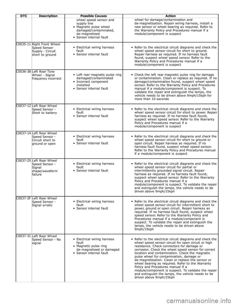
DTC Description Possible Causes Action wheel speed sensor and
supply line
Magnetic pulse wheel
damaged/contaminated,
de-magnetised
Sensor internal fault wheel for damage/contamination and
de-magnetisation. Repair wiring harness, install a
new sensor or wheel bearing as required. Refer to
the Warranty Policy and Procedures manual if a
module/component is suspect C0035-11
Right Front Wheel
Speed Sensor
Supply - Circuit
short to ground
Electrical wiring harness
fault
Sensor internal fault
Refer to the electrical circuit diagrams and check the
wheel speed sensor circuit for short to ground.
Repair harness as required. If no harness fault
found, suspect wheel speed sensor. Refer to the
Warranty Policy and Procedures manual if a
module/component is suspect C0036-38
Left Rear Tone
Wheel - Signal
frequency incorrect
Left rear magnetic pulse ring
damaged/contaminated
Incorrect component
installed
Sensor internal fault
Check the left rear magnetic pulse ring for damage
or contamination. Clean or replace as required. If no
damage/contamination found, suspect wheel speed
sensor. Refer to the Warranty Policy and Procedures
manual if a module/component is suspect. To
validate the repair and extinguish the lamps, the
vehicle needs to be driven above 9mph/15kph for
more than 10 seconds C0037-12
Left Rear Wheel
Speed Sensor -
Short to battery
Electrical wiring harness
fault
Sensor internal fault
Refer to the electrical circuit diagrams and check the
wheel speed sensor circuit for short to power. Repair
harness as required. If no harness fault found,
suspect wheel speed sensor. Refer to the Warranty
Policy and Procedures manual if a
module/component is suspect C0037-14
Left Rear Wheel
Speed Sensor -
Circuit short to
ground or open
Electrical wiring harness
fault
Sensor internal fault
Refer to the electrical circuit diagrams and check the
wheel speed sensor circuit for short to ground or
open circuit. Repair harness as required. If no
harness fault found, suspect wheel speed sensor.
Refer to the Warranty Policy and Procedures manual
if a module/component is suspect C0037-25
Left Rear Wheel
Speed Sensor -
Signal
shape/waveform
failure
Electrical wiring harness
fault
Sensor internal fault
Refer to the electrical circuit diagrams and check the
wheel speed sensor circuit for partial or
intermittently grounded signal circuit. Repair
harness as required. If no harness fault found,
suspect wheel speed sensor. Refer to the Warranty
Policy and Procedures manual if a
module/component is suspect. To validate the repair
and extinguish the lamps, the vehicle needs to be
driven above 9mph/15kph C0037-2F
Left Rear Wheel
Speed Sensor -
Signal erratic
Electrical wiring harness
fault
Sensor internal fault
Refer to the electrical circuit diagrams and check the
wheel speed sensor circuit for intermittent short to
power, ground or open circuit. Repair harness as
required. If no harness fault found, suspect wheel
speed sensor. Refer to the Warranty Policy and
Procedures manual if a module/component is
suspect. To validate the repair and extinguish the
lamps, the vehicle needs to be driven above
9mph/15kph C0037-31
Left Rear Wheel
Speed Sensor - No
signal
Electrical wiring harness
fault
Magnetic pulse ring
de-magnetised or damaged
Sensor internal fault
Refer to the electrical circuit diagrams and check the
wheel speed sensor circuit for open circuit or high
resistance. Check connectors for damage or
corrosion. Check the wheel speed sensor for correct
location and contamination. Check the magnetic
pulse wheel for contamination, damage or
de-magnetisation. Clean or replace the sensor or
wheel bearing as required. Refer to the Warranty
Policy and Procedures manual if a
module/component is suspect. To validate the repair
and extinguish the lamps, the vehicle needs to be
driven above 9mph/15kph