2010 JAGUAR XFR Rear Drive
[x] Cancel search: Rear DrivePage 1849 of 3039
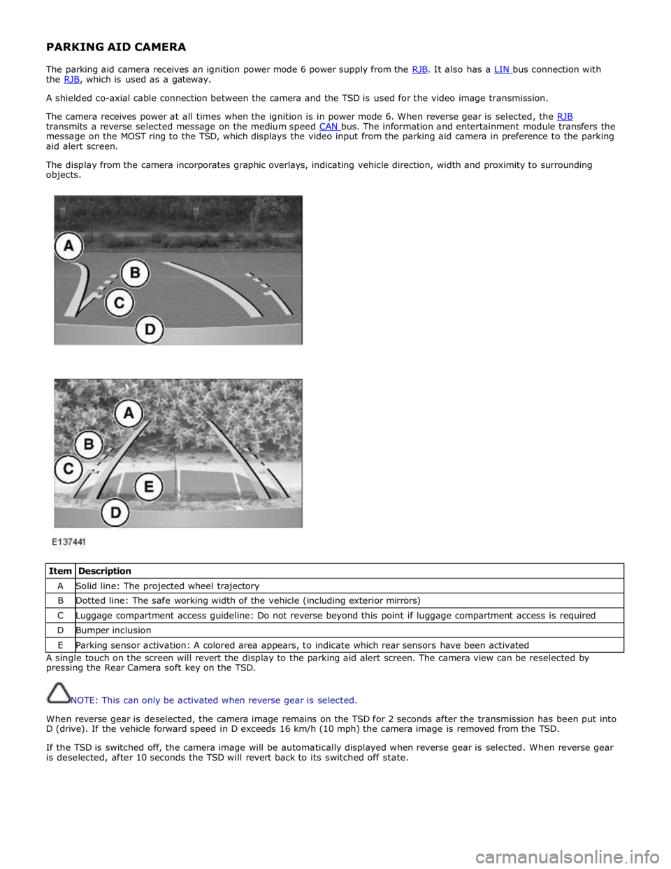
PARKING AID CAMERA
The parking aid camera receives an ignition power mode 6 power supply from the RJB. It also has a LIN bus connection with the RJB, which is used as a gateway. A shielded co-axial cable connection between the camera and the TSD is used for the video image transmission.
The camera receives power at all times when the ignition is in power mode 6. When reverse gear is selected, the RJB transmits a reverse selected message on the medium speed CAN bus. The information and entertainment module transfers the message on the MOST ring to the TSD, which displays the video input from the parking aid camera in preference to the parking
aid alert screen.
The display from the camera incorporates graphic overlays, indicating vehicle direction, width and proximity to surrounding
objects.
Item Description A Solid line: The projected wheel trajectory B Dotted line: The safe working width of the vehicle (including exterior mirrors) C Luggage compartment access guideline: Do not reverse beyond this point if luggage compartment access is required D Bumper inclusion E Parking sensor activation: A colored area appears, to indicate which rear sensors have been activated A single touch on the screen will revert the display to the parking aid alert screen. The camera view can be reselected by
pressing the Rear Camera soft key on the TSD.
NOTE: This can only be activated when reverse gear is selected.
When reverse gear is deselected, the camera image remains on the TSD for 2 seconds after the transmission has been put into
D (drive). If the vehicle forward speed in D exceeds 16 km/h (10 mph) the camera image is removed from the TSD.
If the TSD is switched off, the camera image will be automatically displayed when reverse gear is selected. When reverse gear
is deselected, after 10 seconds the TSD will revert back to its switched off state.
Page 1882 of 3039

11 Secondary battery 12 Dual Battery Junction Box (DBJB) 13 Rear Junction Box (RJB) 14 Megafuse 15 Battery Junction box (BJB) 16 Primary battery
System Operation BATTERY MONITORING SYSTEM - TD4 2.2L DIESEL VEHICLES ONLY
Periodically the battery monitoring system module will instigate a self-calibration routine. To self calibrate, the battery
monitoring system first charges the battery to its full condition.
NOTE: If the vehicle is only driven for short periods the charging process could take a number of days to complete.
Once the battery is fully charged, the battery monitoring system will discharge the battery to approximately 75% of its full
state of charge, but never lower than 12.2 V. The time taken to complete this part of the routine is dependent on the electrical
load on the vehicle.
When the second part of the routine has been successfully completed, the battery monitoring system will return the battery to
its optimum level of charge. The optimum level of charge will be between 12.6 V and 15 V, depending on battery condition,
temperature and loading.
The battery monitoring system module also monitors the battery condition with the engine switched off. If a low voltage
condition is detected the module can request the infotainment system is switched off to protect battery voltage. Once the
infotainment system has been switched off, the vehicle must be run for at least 5 minutes to charge the battery before the
infotainment system can be operated with the engine switched off.
BATTERY MONITORING SYSTEM - SINGLE AND DUAL BATTERY SYSTEM VEHICLES
When the ignition is off (power mode 0), the BMS control module records the primary battery state of charge and begins to
monitor the battery condition from this point.
If the battery state of charge falls by 7%, the BMS control module will monitor the primary battery for 5 minutes. If after the 5
minute monitoring period, the primary battery charge has continued to fall due to the quiescent drain current being too high,
the BMS control module will determine that some control modules are still 'awake'. The BMS control module sends a shutdown
message on the LIN (local interconnect network) bus to the GWM (Gateway Module). The GWM sends a CAN (controller area
network) bus message on both the medium and high speed networks to all control modules, requesting them to shutdown.
The BMS control module will monitor the primary battery state of charge for a further 5 minutes and determine if the primary
battery state of charge is still dropping. If a quiescent drain current continues, the primary battery state of charge will
continue to drop. If the state of charge falls to 12% of the initial monitoring value, the BMS control module determines that
one or more control modules are still awake and a failure to respond to the shutdown request may indicate an error state
within the control module(s).
BMS Low Battery Warning and Energy Management Messages
The BMS continuously monitors the condition of the primary vehicle battery. If excessive battery discharge occurs, the system
will begin to shut down non-essential electrical systems in order to protect the battery.
If the BMS calculates that battery condition is not within set parameters, there are 3 messages that can be displayed, 2 on the
touch screen and 1 on the message center. These inform the user that the battery is either at a low level of charge or the
engine-off power consumption limit has been exceeded.
Low Battery - Please switch engine on or system will shutdown in 3 minutes: is displayed as a Warning on the
touch screen if the engine is not running. This indicates that the battery has fallen below a predefined threshold. As
soon as the battery is charged back above this threshold then the message will be removed.
Low Battery - Please start your engine is displayed on the message center if the engine is not running. This indicates
that the battery has fallen below a predefined threshold. As soon as the battery is charged back above this threshold
then the message will be removed or it can be manually removed by pressing 'OK'.
System will shut down in 3 minutes: is displayed as an Energy management on the touch screen if the engine is not
running, and system features are causing excessive battery discharge. After 3 minutes the BMS will begin shutting
down vehicle systems. Normal system operation will resume when the engine is started.
This is based on a percentage of battery capacity available for the customer to use with the engine off. The percentage can
change based upon several factors.
Once triggered, the resetting of this message will not occur until the vehicle is driven for 10 minutes with the engine running
(to allow the battery to recoup any lost charge). However, if the engine is run for less than 10 minutes, the message will only
be displayed after an additional 5 minutes with the ignition on but engine off.
BMS Control Module Self Calibration
Periodically the BMS control module will instigate a self-calibration routine. To self calibrate, the battery monitoring system www.JagDocs.com
Page 1958 of 3039
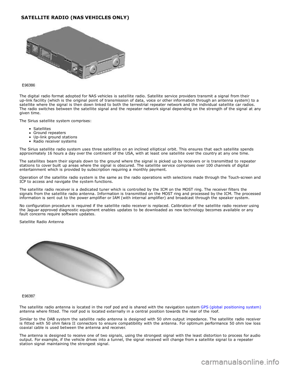
The digital radio format adopted for NAS vehicles is satellite radio. Satellite service providers transmit a signal from their
up-link facility (which is the original point of transmission of data, voice or other information through an antenna system) to a
satellite where the signal is then down linked to both the terrestrial repeater network and the individual satellite car radios.
The radio switches between the satellite signal and the repeater network signal depending on the strength of the signal at any
given time.
The Sirius satellite system comprises:
Satellites
Ground repeaters
Up-link ground stations
Radio receiver systems
The Sirius satellite radio system uses three satellites on an inclined elliptical orbit. This ensures that each satellite spends
approximately 16 hours a day over the continent of the USA, with at least one satellite over the country at any one time.
The satellites beam their signals down to the ground where the signal is picked up by receivers or is transmitted to repeater
stations to cover built up areas where the signal is obscured. The satellite service comprises over 100 channels of digital
entertainment which is provided by subscription requiring a monthly payment.
Operation of the satellite radio system is the same as the radio operations with selections made through the Touch-screen and
ICP to access and navigate the system functions.
The satellite radio receiver is a dedicated tuner which is controlled by the ICM on the MOST ring. The receiver filters the
signals from the satellite radio antenna. Information is transmitted on the MOST ring and processed by the ICM. The processed
information is sent out to the power amplifier or IAM (with internal amplifier) and broadcast through the speaker system.
No configuration procedure is required if the satellite radio receiver is replaced. Calibration of the satellite radio receiver using
the Jaguar approved diagnostic equipment enables updates to be downloaded as new technology becomes available or any
fault concerns require software updates.
Satellite Radio Antenna
The satellite radio antenna is located in the roof pod and is shared with the navigation system GPS (global positioning system)
antenna where fitted. The roof pod is located externally in a central position towards the rear of the roof.
Similar to the DAB system the satellite radio antenna is designed with 50 ohm output impedance. The satellite radio receiver
is fitted with 50 ohm fakra II connectors to ensure compatibility with the antenna. For optimum performance 50 ohm low loss
coaxial cable is used between the antenna and receiver.
The antenna is designed to receive one of two signals, using the strongest signal with the least distortion to process for audio
output. For example, if the vehicle drives into a tunnel, the signal received will change from a satellite signal to a repeater
station signal maintaining the strongest signal. SATELLITE RADIO (NAS VEHICLES ONLY)
Page 1960 of 3039

Publi s hed: 11-May-2011
Information and Entertainment System - Speakers - Overview
Des cript ion and Operat ion
Overview
The vehi cl e has t hree l evels of audio s ys t em availabl e:
Jaguar Sound Sys temJaguar Premi um Sound Syst emBowers & W i lkins Surround Sound Sys temThe Jaguar Sound Sys tem has 8 s peakers, compri s ing an i dent ical mid-bas s and t weeter combinati on in each door. Al l
s peaker domes in this sys tem are of st andard t ext il e cons t ructi on. The s peakers are driven direct ly by the IAM (i nt egrat ed
audi o module) i nternal ampli fi er.
The Jaguar 320W Premium Sound Sys tem has 9 s peakers including mid-bas s and t weet ers in t he doors , addi ng a
s ub-woofer in the spare wheel wel l. The s peakers are driven by an Al pi ne AUD 8 ampli fier l ocat ed in t he LH (left-hand)
s ide of t he luggage compartment .
The Bowers & W i lkins 440W Surround Sound Syst em us es an Al pi ne AUD 12 amplifier, a Dolby Pro-Logi c 2 7.1 Surround
Sound Sys t em and has 14 s peakers. This layout adds a mid-range s peaker to each front door whi le ret ai ning a mid-bas s
and t weet er in each rear door. It als o adds an i ns t rument panel center s peaker, 2 s urround-effect speakers i n t he rear
parcel shelf, and has the luggage compart ment-mounted sub-woofer as the Jaguar 320W Premi um Sound Sys t em. The
s peakers are driven by an AUD 12 power ampl ifier located i n t he luggage compartment .
The main s peakers on the Jaguar 320W Premium Sound Sys t em and t he Bowers & W i lkins 440W Surround Sound Syst em
are identi fied by the bright yellow Kevl ar cons truct ed domes which are vis ibl e through the s peaker grill es. The t weeter
s peaker domes are an al uminum cons truct ion. The s ub-woofer s peakers are a text ile dome cons t ructi on.
www.JagDocs.com
Page 1964 of 3039

System Operation
The Jaguar Sound Sys tem has 8 s peakers, compri s ing an i dent ical mid-bas s and t weeter combinati on in each door. Al l
s peaker domes in this sys tem are of st andard t ext il e cons t ructi on. The s peakers are driven direct ly by the IAM (i nt egrat ed
audi o module) i nternal ampli fi er.
The Jaguar 320W Premium Sound Sys tem has 9 s peakers including mid-bas s and t weet ers in t he doors , addi ng a
s ub-woofer in the spare wheel wel l. The s peakers are driven by an Al pi ne AUD 8 ampli fier l ocat ed in t he LH s i de of the
luggage compartment .
The Bowers & W i lkins 440W Surround Sound Syst em us es an Al pi ne AUD 12 amplifier, a Dolby Pro-Logi c 2 7.1 Surround
Sound Sys t em and has 14 s peakers. This layout adds a mid-range s peaker to each front door whi le ret ai ning a mid-bas s
and t weet er in each rear door. It als o adds an i ns t rument panel center s peaker, 2 s urround-effect speakers i n t he rear
parcel shelf, and has the luggage compart ment-mounted sub-woofer as the Jaguar 320W Premi um Sound Sys t em. The
s peakers are driven by an AUD 12 power ampl ifier located i n t he luggage compartment .
The main s peakers on the Jaguar 320W Premium Sound Sys t em and t he Bowers & W i lkins 440W Surround Sound Syst em
are identi fied by the bright yellow Kevl ar cons truct ed domes which are vis ibl e through the s peaker grill es. The t weeter
s peaker domes are an al uminum cons truct ion. The s ub-woofer s peakers are a text ile dome cons t ructi on.
Page 1973 of 3039

Published: 11-May-2011
Information and Entertainment System - Navigation System - Overview
Description and Operation
OVERVIEW
The navigation system provides audible and visual route guidance information to enable the driver to reach a desired
destination. The system allows the driver to choose the desired route using minor or major roads and will present 3 routes to
the driver based on user preferences. Directions to hospitals, museums, monuments and hotels are also available. The
navigation computer uses map information stored on a DVD (digital versatile disc) to determine the best route for the journey
and provide the driver with details of directions and approaching junctions.
The navigation system has various levels of user control through the Touch-screen and JaguarVoice system. System volume
adjustment can be made using the ICP (integrated control panel), Touch-screen and steering wheel controls.
There are 3 navigation system variants specific to various markets. On all systems the GPS (global positioning system) signal
is received by the GPS (global positioning system) antenna located in the roof pod antenna module.
The European navigation system includes the TMC (traffic messaging channel) function, which receives traffic information from
an FM antenna integrated into the heated rear window. On a pre-selected route the system will offer re-routing options
depending on traffic conditions.
The Japanese navigation system includes the VICS (vehicle information and communication systems) function. The VICS
(vehicle information and communication systems) supplies information to enable the navigation computer to re-route the
navigation guidance or to inform the vehicle driver of traffic conditions in the vehicles vicinity. Information is provided to the
system through an FM antenna integrated into the heated rear window and a VICS beacon located in the LH upper side of the
instrument panel.
The NAS (North American specification) variant does not include any additional traffic information systems.
The navigation system is primarily controlled from the Touch-screen which is located in the center of the instrument panel.
Control signals from the Touch-screen are sent on the MOST (media oriented systems transport) ring to the navigation
computer. The navigation computer uses a dedicated GVIF (gigabit video interface) bus to transmit video signals to the Touch-
screen.
Depending upon the audio system version fitted the navigation audio output signals are sent on the MOST (media oriented
systems transport) ring to the IAM (integrated audio module) or the power amplifier for speaker output.
Page 1977 of 3039

In addition to the standard navigation system there are two market dependant systems that supply extra information to the
navigation system and the driver. These are:
TMC (traffic message channel) (Europe only)
VICS (vehicle information and communication system) (Japan only)
The TMC (traffic message channel) is a function of the FM (frequency modulation)RDS (radio data system). The system
broadcasts real-time traffic and weather information. Data messages are received and decoded by the TMC (traffic message
channel) integral receiver and processed by the navigation computer. TMC (traffic message channel) messages can be filtered
by the navigation computer so that only those relevant to the current journey are displayed, allowing the navigation system to
offer dynamic route guidance - alerting the driver of a problem on the planned route and calculating an alternative route to
avoid the incident. All TMC (traffic message channel) events on the map can be viewed not just the ones on the calculated
route.
TMC (traffic message channel) traffic information systems conform to a global standard that has been adopted by traffic data
gatherers, information service providers, broadcasters and vehicle/receiver manufacturers.
All TMC (traffic message channel) receivers use the same list of event codes, while the location database (on the map disc)
contains both a country-specific set of location codes for the strategic European road network.
TMC (traffic message channel) traffic data is currently broadcast in many European countries.
The VICS (vehicle information and communication system) is broadcast in the Japanese market.
The VICS (vehicle information and communication system) supplies information to enable the navigation computer to re-route
the navigation guidance or to inform the vehicle driver of traffic conditions in the vehicles vicinity. Information is provided to
the system through 3 routes:
RF (radio frequency) transmission
Infra-red transmission
FM multiplex transmissions
The RF (radio frequency) transmissions are generally transmitted from road side beacons mainly on expressways. The
information transmitted is as follows:
Traffic congestion
Travel time to next intersection
Traffic conditions in surrounding areas and expressway turn offs
Traffic accidents
Speed limits
Lane regulations
Tire change
Parking availability at expressway service areas and parking areas
Infra-Red transmissions are transmitted from road side beacons on major trunk roads. The information transmitted is:
Traffic congestion and travel time
Traffic accidents
Breakdowns
Road works restrictions
Parking availability
FM transmissions are broadcast as part of the FM multiplex broadcasting system from NHK FM stations. Information transmitted is:
Traffic congestion and travel time for wide areas
Traffic accidents, road works, speed limits and lane restrictions for a wide area
Parking availability information
The traffic data is split from the normal FM transmissions by the diversity antenna module.
Selection of 'Navigation' on the Touch-screen home menu and subsequent sub-menu selection sends a control request signal to
the navigation computer on the MOST (media orientated systems transport) ring. The requested control information is
processed by the navigation computer.
If voice guidance is operational the voice signal information is relayed from the navigation computer on the MOST (media
orientated systems transport) ring to either the IAM (integrated audio unit) or Power Amplifier, dependant on equipment level,
for output on the speaker system. The navigation audio output is through the front speakers whilst the background audio, for
example radio or CD (compact disc), is played at a reduced volume on the rear speakers.
The GPS signal is available to the navigation system at all times when the vehicle ignition is switched on.
Navigation user voice commands are made using the JaguarVoice system. The ICM (information control module) processes the
analogue signal from the JaguarVoice switch into a digital signal. The digital signal is passed from the ICM (information control
module) onto the MOST (media orientated systems transport) system to the JaguarVoice control unit which is integral with the
navigation computer.
The navigation computer sends an instruction via the MOST (media orientated systems transport) ring to the IAM (integrated
audio module) to turn on the microphone facility.
The microphone is hardwired to the IAM (integrated audio module). The spoken voice command signals are relayed from the
IAM (integrated audio module) via the MOST (media orientated systems transport) ring to the navigation computer for
Page 2022 of 3039

The lighting system has an 'auto' lights function which is controlled by the CJB on receipt of signals from the rain/light sensor located at the top of the windscreen. The exterior lights are turned on or off in response to ambient light signals from the
rain/light sensor on a LIN (local interconnect network) bus connection to the CJB . The auto lights can also be activated when the windshield wipers are activated by signals from the rain sensor, which is located at the top of the windshield or when the
driver activates the wipers in the fast wipe position.
Two levels of headlamp specification are available; halogen or xenon. In certain markets the headlamps feature a cornering
lamp or a static bending lamp which illuminates the area at the side of the vehicle when turning into driveways for example.
North American Specification (NAS) vehicles have a side marker lamp installed in the headlamp assembly. Replacement of any
of the headlamp bulbs requires removal of the headlamp assembly.
The tail lamp comprises two separate lamp assemblies. The turn signal indicator, side and stop lamps and reverse lamps are
located in each rear fender tail lamp assembly. The rear fog lamps are located in separate units attached to the luggage
compartment lid. A side marker lamp is fitted to the rear fender tail lamp assembly and is fitted in all markets.
Two systems of headlamp leveling are available; manual leveling which is only available on halogen headlamps and static
dynamic leveling which is available on xenon headlamps. The manual system uses a thumbwheel rheostat to adjust the
vertical alignment of the headlamps to compensate for differing vehicle loading. The static dynamic system uses height
sensors fitted to the front and rear suspension and a headlamp leveling module which periodically monitors the vehicle
attitude and adjusts the headlamp vertical alignment accordingly.